Advertisement
Quick Links
Advertisement

Subscribe to Our Youtube Channel
Related Manuals for Rtelligent RS Series

Summary of Contents for Rtelligent RS Series
- Page 1 RS series Servo System Quick start guide 2020-10 version 3.0...
- Page 2 Cautions Thank you for using the RS series AC servo system! This operating manual provides information about the RS series drivers and RSM series motors. Before use, please read the manual carefully to ensure proper use! Please disconnect the power supply for more than 5 minutes before removing or disassembling the driver, otherwise it may cause electric shock due to residual voltage.
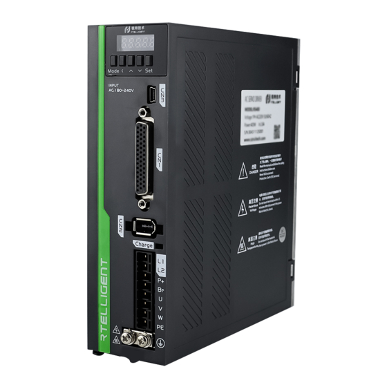
- Page 3 Model combination list 485 communication port (CN4, CN5) Panel operator USB debugging port (CN3) Input and output signal terminals (CN1) Power supply input Encoder interface (CN2) Motor interface Braking resistor (can be external) Grounding port Servo driver dimension drawing Below 400W Below 1500W Absolute battery box dimensions Below 3000W...
- Page 4 List of standard model combinations Rated power Matching driver Encoder cable Motor base Model Power cable RSM-M04J0130A RS100(E) SES4-030 SMS-030 RSM-M04J0330A 100W RS100(E) SES4-030 SMS-030 RSMA-M06J0630A 200W RS200(E) SES4-030 SMS-030 RS400(E) RSMA-M06J1330A 400W SES4-030 SMS-030 RSMA-M08J2430A 750W RS750(E) SES4-030 SMS-030 RSMA-M08J3230A RS1000(E) SMS-030...
- Page 5 Motor model description Motor rated speed Encoder resolution RSM Series Servo Motor A:5 pole pairs,Ultra thin J: 17bit magnetic encoder 30: 3000 rpm 15: 1500 rpm none: 4 pole pairs H: 23bit optical encoder Oil seal or not G: 17bit magnetic Multi-turn absolute encoder Motor inertia code L: 23bit optical Multi-turn absolute encoder A: with oil seal...
- Page 6 CN1-DB44 control signal interface definition Signal Functions Signal definition Description Default function Pin number PUL+ Differential pulse positive PUL- Differential pulse negative External Differential input, 5V pulse DIR+ Differential direction positive interface Differential direction negative DIR- 24VPUL+ 24V pulse positive 24V positive 24VDIR+ 24V direction positive...
- Page 7 Display and panel operation Symbol Description Diagram Functions MODE Mode/Return Mode switch Shift key Shift left Switch up selection or increase value Increase Switch down selection or decrease Decrease the value Confirm operation Confirm Operation progress of parameters SAVE Long Press KEY‘SET’ READ RESET Short Press KEY‘MODE’...
- Page 8 Monitor State Content Unit Content Run statement —— speed of motor speed command motor torque torque command Run current Command unit(pulse) Position command counter Position feedback counter Encoder unit(pulse) Encoder unit Position error Pulse command speed Pulse command frequency Input signal state ——...
- Page 9 Operation guide for position control mode Single-phase 220VAC Motor cable Encoder cable 24VPUL+ PUL+ Pulse PUL- 24VDIR+ SV-RDY DIR+ Direction DIR- OUT4 24V+ OUTCOM- INCOM SV-ON Servo enable BRK+ BRK- Positive limit DFOUT6+ DFOUT6- Negative limit ALMRST Alarm clear DFEA+ DFEA- DFEB+ DFEB-...
- Page 10 Wiring diagram of holding brake 24V+ Relay BRK+ BRK- RS SERVO DRIVER 24V- Servo motor with brake Servo driver Remarks: 1. The output signal of brake control can only be specified as OUT5 or OUT6 port, OUT5 is shown as default. 2.
- Page 11 Operation guide for torque control mode Single-phase 220VAC Motor cable Encoder cable AN1+ Analog 1 A/D1 -10~+10 AN1- SV-RDY AN2+ Analog 2 A/D2 -10~+10 AN2- ANGND OUT4 31 OUTCOM- 24V+ INCOM BRK+ BRK- SV-ON Servo enable DFOUT6+ Positive limit DFOUT6- Negative limit ALMRST Alarm clear...
- Page 12 Analog input processing procedure Zero drift/ P02.74 P02.76 Filter Analog 1 input offset/dead Command ratio processing An2 processed An1 input zone correction voltage voltage Zero drift/ P02.75 P02.77 Filter Analog 2 input offset/dead Command ratio processing An2 input zone correction An2 processed voltage voltage Basic parameters of torque control mode...
Need help?
Do you have a question about the RS Series and is the answer not in the manual?
Questions and answers