Table of Contents
Advertisement
Quick Links
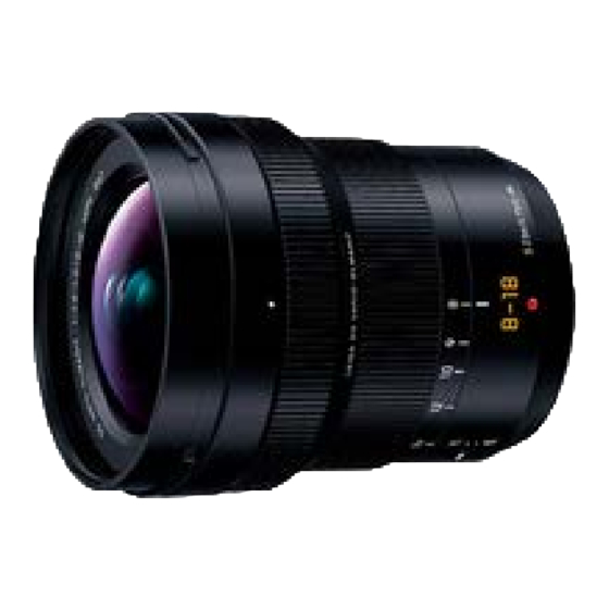
Interchangeable Lens for Digital Camera
H-E08018PP
Model No.
H-E08018E
H-E08018GK
© Panasonic Corporation 2017 Unauthorized copying and distribution is a violation of law.
file:///C|/U...l/Temp/Rar$EXa0.719/viewing/SGML_VIEW_DATA/ALL/H-E08018PP/SVC/DSC1705017CE/doc/DSC1705017CE_cvr.xml[11/11/2018 4:59:45 PM]
ORDER NO.DSC1705017CE
B26
Advertisement
Table of Contents


Need help?
Do you have a question about the H-E08018PP and is the answer not in the manual?
Questions and answers