Table of Contents
Advertisement
Advertisement
Table of Contents

Related Manuals for Fagor DDS


Summary of Contents for Fagor DDS
- Page 1 DRIVE Hardware manual Ref.1310...
- Page 2 Registered trademarks All registered trade marks, even those not indicated are also acknowl- Fagor Automation S. Coop. will not be held responsible for any losses edged. When some are not indicated, it does not mean that they are or damage, direct, indirect or by chance that could result from that in- free.
-
Page 3: Table Of Contents
GENERAL INDEX DESCRIPTION ......................25 Description ........................... 26 General diagram .......................... 27 Stages of the system configuration....................28 Environmental and operating conditions..................29 Electrical conditions ........................29 POWER SUPPLIES ..................... 31 Non-regenerative power supplies ....................32 Regenerative power supplies....................... 50 Regenerative regulated power supplies.................. - Page 4 Connection between modules....................279 Power supply connections ......................291 Connection of the control and communications signals............. 293 Check the installation......................... 311 FUNCTIONAL SAFETY ..................... 313 STO safety function ........................314 Interface ............................. 315 Examples ........................... 316 Precautions ..........................318 Risk analysis ..........................319 Technical data of the safety function ..................
- Page 5 Order example ........................... 376 Module identification ........................377 COMPATIBILITY......................379 Mains voltage..........................379 Compatibility ..........................379 Module replacement ........................380 VECON board ..........................380 VECON-2 board......................... 380 VECON-3 board......................... 381 VECON-4 board......................... 381 Boot for VECON-2 ........................381 Boot for VECON-3 ........................381 Boot for VECON-4 ........................
- Page 6 HARDWARE Ref.1310...
- Page 7 Bº San Andrés 19; C.P. 20500, Mondragón, Gipuzkoa - Spain. We hereby declare, under our responsibility the conformity of the product: FAGOR DDS SERVO DRIVE SYSTEM consisting of the following modules and accessories: APS-24, PS-25B4, PS-65A, XPS-25, XPS-65, RPS-80, RPS-75, RPS-45, RPS-20 AXD/SPD 1.08, 1.15, 1.25, 1.35, 2.50, 2.75, 2.85, 3.100, 3.150, 3.200, 3.250...
- Page 8 Fagor Automation, S. Coop. Equipment with date in serial number greater than 2012-05 meets this certification. The date appears on the version label stuck on the outside of the drive module. Equipment included in the EC-Type-Examination: TÜV SÜD: AXD X.XXX-A1-X-X AXD X.XXX-SI-X-X...
- Page 13 1 of this manual. Warning WARNING. The information described in this manual may be subject to changes due to technical modifications. FAGOR AUTOMATION, S. Coop. reserves the right to change the contents of this manual without prior notice. Headquarters Fagor Automation, S. Coop.
- Page 14 - A B O U T T H E P R O D U C T - Software options Bear in mind that some of the features or applications described in this manual depend on the soft- ware version installed. These considerations are reflected in the “man_dds_soft.pdf” manual supplied with this one.
- Page 15 - S H I P P I N G C O N D I T I O N S , S T O R AG E A N D R E C YC LI N G - Shipping When shipping the unit, do it protected against blows and pack it in its original cardboard box with its original packing material.
- Page 16 HARDWARE Ref.1310...
- Page 17 From February of 2004 on, compact drive modules ACD 2.50, SCD 2.50, ACD 2.75, SCD 2.75, CMC 2.50, CMC 2.75 and the program- ming module DDS PROG MODULE will no longer be in Fagor Auto- mation’ catalog. However, all the documentation regarding them is...
- Page 18 Manual reference Events 0602 New compact drives: ACD/SCD/CMC 1.25A New compact drives: ACD/SCD/CMC 2.35 New resistors: ER-33/550 and ER-18/900 (as accessory) Regenerative regulated power supplies. Boost (step-up) power Supplies: RPS-75, RPS-45 and RPS-20. Choke RPS-75, choke RPS-45 and choke RPS-20. 0606 No new hardware has been implemented.
- Page 19 They must also know the current regulations and standards for preventing accidents that must be borne in mind when handling these units. Fagor Automation shall not be held responsible of any physical or material damage originated from not complying with these basic safety rules.
- Page 20 This unit is ready to be used in industrial environments and comply with the current directives and regulations of the European Community. Fagor Automation shall not be held responsible for any damage that could suffer or cause when in- stalled under other conditions (residential or domestic environments).
- Page 21 Precautions during repairs Do not access the inside of this unit. Only personnel authorized by Fagor Automation may access the interior of this unit. Do not handle the connectors while the unit is connected to mains. Before handling the connectors (mains, moving power, feedback, ...) make sure that the unit is not connected to mains.
- Page 22 Fagor is committed to repairing and replacing its products from the time when the first such product was launched up to 8 years after such product has disappeared from the product catalog. It is entirely up to FAGOR AUTOMATION S. Coop. to determine whether a repair is to be considered under warranty. Exclusive clauses The repair will be done in our facilities;...
- Page 23 - A D D IT I O N A L N O T E S - Install the DDS servo drive system away from coolants, chemicals, blows, etc that could damage it. Before turning the unit on, verify that the ground connections have been made properly. See chapter 8.
- Page 24 CD-ROM Product selection guides Document Description Format It describes the products that make up the dds man_drive_ord_hand.pdf system and allows selecting each element ac- (only in english) cording to the user's needs. It describes the FM7/FM9 asynchronous mo- man_fm7/fm9_ord_hand.pdf...
-
Page 25: Description
DESCRIPTION The DDS servo drive system is ready to be used in industrial environments. It may be used with the CNC to control the movements and devices of the ma- chine. The configuration of the main DDS servo drive system follows this gener-... -
Page 26: Description
400-4.5% V AC and a variable frequency with which it will govern its speed. Certain mandatory protection devices must be added between the mains lines and the DDS servo drive system. Others may be optional. These el- ements are: Main switch... -
Page 27: General Diagram
Description 1.2 General diagram See the schematic description of all the elements that make up the DDS servo drive system: Mains connection. Non-Regenerative PS-65A Three phase 50/60Hz.TN mains Power Supplies + modular drives: 400-10% to 460+10% V AC... -
Page 28: Stages Of The System Configuration
Description 1.3 Stages of the system configuration The following steps are a reference to configure and install the DDS sys- tem. NOTE. This DDS system configuration process assumes that the mo- tors of the system are known motors. -
Page 29: Environmental And Operating Conditions
Description 1.4 Environmental and operating conditions Conditions Standard Test reference Mechanical specifications Vibration Acc. to Class 2M1, vibration sinusoidal Transport IEC 60721-3-2 2 Hz < f <= 9 Hz, 3.5 mm amplitude 9 Hz < f <= 200 Hz, 1 g 200 Hz <... - Page 30 Description HARDWARE Ref.1310...
-
Page 31: Power Supplies
POWER SUPPLIES The FAGOR power supplies are connected after the filter to mains (see figure F. H1/1) with a mains voltage between 400 and 460 V AC at a mains frequency of 50/60 Hz and its functions are: Provide a DC voltage output that will supply the drive modules through the power bus. -
Page 32: Non-Regenerative Power Supplies
Power supplies 2.1 Non-regenerative power supplies When referring to non-regenerative power supplies, we'll use PS-25B4 and PS-65A. They all admit a voltage range between 400 to 460 V AC. They are: L1 L2 L3 L+ Re F. H2/1 HARDWARE Non-regenerative power supplies: A. - Page 33 Power supplies PS-65A module Technical data T. H2/1 Technical characteristics. PS-65A Three-phase 50/60 Hz, with a voltage range Power supply (Vmains) between 400-10% and 460+10% V AC Mains power consumption (400 V AC) 95 Arms Maximum connection cable section 50 mm²...
- Page 34 Power supplies Power diagram 65 kW 1.9 kW 2x ER+TH-18/1100 2x ER+TH-18/1800 2.6 kW Power 2x ER+TH-18/2200 4.0 kW Internal Ballast 600 W Always install the two resistors (2x) in parallel, never in series. F. H2/2 Power diagram. Block diagram HARDWARE Ref.1310...
- Page 35 Power supplies PS-65A. Connector description The non-regenerative power supply PS-65A has the following connectors: CAUTION. touch current greater than 3.5 mA. Install ground wire of at least 10 mm² Cu or 16 mm² Al. N O T E . C u r r e n t l y p i n 4 <POWER BUS ENABLE>...
- Page 36 Selecting “resistor disabled” implies disablilng the I2t protection. There is a risk of destroying the resistor without warning. Select only this switch setting when installing a resistor of more power than the ones supplied by FAGOR. T. H2/3 Layout of the switch after selecting the resistor.
- Page 37 Power supplies PS-25B4 module Technical data T. H2/4 Technical characteristics. PS-25B4 Three-phase 50/60 Hz, with a voltage range Power supply (Vmains) between 400-10% and 460+10% V AC Mains power consumption (400 V AC) 36 Arms Maximum connection cable section 10 mm²...
- Page 38 Power supplies Power diagram 25 kW ER+TH-18/1100 950 W ER+TH-18/1800 1.3 kW ER+TH-18/2200 2.0 kW Power ER+TH-18/1000+FAN 2.0 kW ER+TH-18/1500+FAN 3.0 kW 4.0 kW ER+TH-18/2000+FAN Internal Ballast 500 W F. H2/5 Power diagram. Block diagram HARDWARE Ref.1310 F. H2/6 Block diagram.
- Page 39 Power supplies PS-25B4. Connector description The non-regenerative power supply PS-25B4 has the following connectors: CAUTION. AC touch current greater than 3.5 mA. Install ground wire of at least 10 mm² Cu or 16 mm² Al. F. H2/7 Connectors of the PS-25B4 power supply. Power connector for the three-phase mains.
- Page 40 Power supplies Lights indicating the status of the main power supply The non-regenerative power supply PS-25B4 has the following lights on the front panel to indicate the status of the main power supply. FAULT blinking. The blinking red led indicates that there are no er- rors and that one or several mains phases are missing.
- Page 41 Power supplies NOTE. This is the current model with three micro-switches to configure the selection of the Ballast resistor installed. The non-regenerative power supply PS-25B4 has three switches on the front and next to connector X1 (see figure) for selecting the external Bal- last resistor.
- Page 42 Power supplies Power connectors Terminal strip for mains connection When connecting the power supplies to mains through terminals L1, L2 and L3, the phases may be connected in any order. T he R S T ph ase s FROM MAINS may be connected in any sequence.
- Page 43 Power supplies Terminal strip to connect the Ballast resistor The power supply is supplied from factory with a wire jumper between ter- minals Ri and L+. This configuration of the power supply means that it comes from the factory with its internal Ballast resistor. However, if with this internal resistor it is not possible to dissipate enough power (e.g.
- Page 44 2.3 and 2.8 Nm. This point is very important to ensure good electrical con- tact between modules. FAGOR power supplies have a Soft Start for charging the power bus. The soft start begins when two necessary and sufficient conditions are verified: •...
- Page 45 Remember that the purpose of connecting an auxiliary power supply APS- 24 to the DC bus of a DDS system is to ensure the supply to all the con- trol circuits of the power supply and of the drive modules connected to the...
- Page 46 Power supplies Other connectors X1 connector The communication between all the modules that make up the DDS ser- vo drive system is established through connector X1. F. H2/11 Connection of the internal bus between modules through connector X1.
- Page 47 Power supplies The internal circuits of the non-regenerative power supplies PS-65A re- quire an external 24 V DC supply. This is why its connector X2 has three more pins than for the PS-25B4 power supply that integrates an auxiliary power supply.
- Page 48 Power supplies X3, X4, X5 and X6 connectors These connectors belong to the auxiliary power supply integrated into the main power supply PS-25B4. PS-25B4 400-460 VAC Phoenix 7.62 mm X4 X5 +24 VDC 0 VDC Phoenix 5.08 mm F.
- Page 49 Power supplies Module power-up 1. For PS-65A power supplies: Supply 24 V DC to the control circuits of the power supply through pins 9 and 10 of connector X2. For PS-25B4 power supplies: Apply power to the Auxiliary Power Supply from mains through pins 2 and 3 of connector X3;...
-
Page 50: Regenerative Power Supplies
Power supplies 2.2 Regenerative power supplies When referring to regenerative power supplies, we'll use XPS-25 and XPS-65. They all admit a mains voltage between 400-10% and 460+10% V AC and can return power back to mains. They are: Ri Re L+ Ri Re L+ F. - Page 51 Power supplies XPS modules Technical data T. H2/14 Technical characteristics. XPS-25 XPS-65 Three-phase 50/60 Hz, with a voltage range Power supply (Vmains) between 400-10% and 460+10% V AC Mains power consumption (400 V AC) 36 Arms 95 Arms Maximum connection cable section 16 mm²...
- Page 52 Power supplies Power diagram 25 kW 20 kW ER+TH-18/1100 950 W ER+TH-18/1000+FAN 2.0 kW Power ER+TH-18/1500+FAN 3.0 kW ER+TH-18/2000+FAN 4.0 kW Internal Ballast 520 W To dissipate more than 520 W, connect one of the external resistors indicated on the graphics depending on the power to be dissipated. 65 kW 54 kW 2x ER+TH-18/1100...
- Page 53 Power supplies Block diagram F. H2/16 Block diagram. HARDWARE Ref.1310...
- Page 54 Power supplies XPS-25. Connector description The regenerative power supply XPS-25 has the following connectors: CAUTION. AC touch current greater than 3.5 mA. Install ground wire of at least 10 mm² Cu or 16 mm² Al. Ri Re L+ Ri Re L+ F.
- Page 55 Power supplies Lights indicating the status of the main power supply The regenerative power supply XPS-25 has the following lights on the front panel to indicate the status of the main power supply: FAULT blinking. The blinking red led indicates that there are no er- rors and that one or several mains phases are missing.
- Page 56 Power supplies XPS-65. Connector description The regenerative power supply XPS-65 has the following connectors: C A U T I O N . A C t o u c h c u r r e n t greater 3.5 mA. Install ground wire of at least 10 mm²...
- Page 57 Power supplies Lights indicating the status of the main power supply The regenerative power supply XPS-65 has the following lights on the front panel to indicate the status of the main power supply: FAULT blinking. The blinking red led indicates that there are no er- rors and that one or several mains phases are missing.
- Page 58 Power supplies Power connectors Terminal strip for mains connection When connecting the power supplies to mains, the phases may be con- nected in any order. FROM MAINS The RST phases may be connected in any sequence Cable without connectors MPC-4x ...
- Page 59 Power supplies Terminal strip to connect the Ballast resistor Regenerative power supplies also have a small Ballast Circuit for dissipat- ing energy in case of an emergency. This emergency is issued when there is no connection to mains and the Ballast circuit activating voltage is exceeded.
- Page 60 XPS when the version label of the APS-24 (located on top of it) indi- cates a reference newer than PF 23A. WARNING. Never install an APS-24 to the DC bus of a DDS system with a regenerative power supply XPS if the reference of the APS-24 is PF 23A or older.
- Page 61 Remember that the purpose of connecting an auxiliary power supply APS- 24 to the DC bus of a DDS system is to ensure the supply to all the control circuits of the power supply and of the drive modules connected to the DC...
- Page 62 Power supplies Other connectors X1 connector The communication between all the modules that make up the DDS servo drive system is established through connector X1. F. H2/23 Connection of the internal bus between modules through connector X1. A ribbon cable is provided with each module (power supply or drive) for this connection.
- Page 63 Power supplies The next table shows the signals and other considerations related to each pin of connector X2: T. H2/20 Description of the pins of connector X2. System error RESET input Error RESET (24 V DC; 4.5-7 mA). N.
- Page 64 Power supplies The gap and tightening torque and sections of the screws of the plug-in connectors for X3 and X4, X5, X6 are given by the table: T. H2/21 Data of the plug-in connector for X3. Connector data XPS-25 XPS-65 Nr of poles...
- Page 65 Power supplies Module power-up 1. For the XPS-25 and XPS-65 power supplies: Apply power to the Auxiliary Power Supply from mains through pins 2 and 3 of connector X3; These will power the control circuits of the power sup- ply and provide 24 V DC at connectors X4, X5 and X6.
-
Page 66: Regenerative Regulated Power Supplies
Power supplies 2.3 Regenerative regulated power supplies When referring to regenerative regulated (step-up or boost) power sup- plies, we'll use RPS-80, RPS-75, RPS-45 and RPS-20. They all admit a mains voltage between 400-10% V AC and 460+10% V AC (with a mains frequency of 50/60Hz) and can consume and return to mains sinusoidal DC power with a maximum power factor close to 1. - Page 67 Consequently, they will not require the auxiliary power supply APS-24 to perform this function unless more than 8 A are required. NOTE PRIOR TO INSTALLATION Before installing an RPS power supply when using non-FAGOR motors, re- member that: MANDATORY.
- Page 68 Power supplies RPS modules Technical data T. H2/23 Technical characteristics of the RPS modules. RPS-80 RPS-75 RPS-45 RPS-20 Three-phase 50/60 Hz, with a voltage range Power supply (Vmains) between 400 -10 % and 460 +10 % V AC Rated mains power consumption 80 kW 76 kW...
- Page 69 Power supplies Power diagram 80 kW in S1 104 kW in S6-40 Power 80 kW in S1 104 kW in S6-40 75 kW in S1 97 kW in S6-40 Power 75 kW in S1 97 kW in S6-40 45 kW in S1 59 kW in S6-40 Power...
- Page 70 Power supplies Power derating The following graph shows the maximum rms current in continuous S1 (Pn) and intermittent S6-40% (Pmax) duty cycles for a switching frequen- cy of the power transistors of 8 kHz in a temperature range between 5 °C (41 °F) and 60 °C (140 °F).
- Page 71 Power supplies Power derating graph / RPS-45 T. H2/27 Power derating on RPS-45 power supply (8 kHz). (power in S6-40%) Tamb Pn (power in S1) in °C in °F in kW in kW 45.4 59.0 45.4 59.0 45.4 59.0 41.4 53.9...
- Page 72 Power supplies Operating cycles Load cycle S1 Continuous duty. Operation with constant load and long enough to achieve thermal balance. LOAD CYCLE S1 POWER TIME F. H2/32 Load cycle S1. Load cycle S6-40% Periodic uninterrupted duty cycle with intermittent load. Succession of identical duty cycles, each with a running period under constant load and another period without load.
- Page 73 Power supplies Block diagram F. H2/35 Block diagram. HARDWARE Ref.1310...
- Page 74 Power supplies RPS-80. Connector description The following figure shows the regenerative regulated power supply RPS-80 and its connector layout: L1 L2 L3 Top view L1 L2 L3 CAUTION. AC touch current greater than 3.5 mA. Install ground wire of at least 10 mm² Cu or 16 mm²...
- Page 75 Power supplies RPS-75. Connector description The following figure shows the regenerative regulated power supply RPS-75 and its connector layout: L1 L2 L3 Top view L1 L2 L3 CAUTION. AC touch current greater than 3.5 mA. Install ground wire of at least 10 mm² Cu or 16 mm²...
- Page 76 Power supplies RPS-45. Connector description The following figure shows the regenerative regulated power supply RPS-45 and its connector layout: L1 L2 L3 Top view L1 L2 L3 CAUTION. AC touch current greater than 3.5 mA. Install ground wire or at least 10 mm²...
- Page 77 Power supplies RPS-20. Connector description Top view of the The following figure shows the regenerative regulated power supply RPS-20 and its connector layout: connectors Top view of the L1 L2 L3 connectors CAUTION. AC touch current greater than 3.5 mA. Install ground wire or at least 10 mm²...
- Page 78 FAULT turned ON. Red LED on all the time. It indicates that there is an error either at the power supply or in some module of the DDS system. The error will be shown at the display of the power supply - see the sec- tion “status display”...
- Page 79 Considering that it has been set to its default value (650 V DC), this switch configuration could also be set in both cases of this example. For further information on parameter VP5 of the RPS power supplies, con- tact Fagor Automation S. Coop. HARDWARE Ref.1310...
- Page 80 Power supplies Power connectors Terminal strip for mains connection This connector may be used to connect the power supply to mains. When connecting the power suppliy to mains, the phases may be connected in any order RST, RTS, TRS, etc. From mains The RST phases may be connected in any sequence at the power connector.
- Page 81 Connection to an external braking resistor (Ballast) RPS power supplies do not carry a Ballast circuit and, consequently, FAGOR does not have external braking resistors (Ballast) associated with them. In applications requiring a Ballast circuit, one off-the-shelf will have to Ref.1310...
- Page 82 2.3 and 2.8 N·m. This point is very important to ensure good electrical contact between modules. FAGOR power supplies have a soft-start for charging the power bus. The soft start begins when these two conditions, that are necessary and sufficient, are met: ...
- Page 83 Remember that the purpose of connecting an auxiliary power supply APS- 24 to the DC bus of a DDS system is to ensure the supply to all the con- trol circuits of the power supply and of the drive modules connected to the...
- Page 84 Installing a choke with an inductance other than the one recom- mended for a choke may cause severe damage to the unit. FAGOR supplies the right CHOKE RPS for this application. See the rele- vant cable section in table T. H2/23. Note that the cable must be shielded.
- Page 85 Power supplies Other connectors X1 and X2 connectors These connectors belong to the auxiliary power supply integrated into the main RPS power supply. This auxiliary power supply is fed through connec- tor X1. This electrical power is received from the three-phase line to the power supply connected to a point before the power connection operation (before power contactor - KM1).
- Page 86 CE requirement for the machine. Example regarding the 24 V DC of connector X2 A door closes an enclosure that contains a DDS system with an RPS power supply. The 24 V DC supplied at pin 1 of connector X2 may be tak- en to one end of the door opening/closing switch and connect the other end to pin 4 <PWM ENABLE>...
- Page 87 This connector may be used to connect the various modules to each oth- er through the internal bus communicating with each other the power sup- ply and all the servo drives that make up the DDS system. F. H2/47 Connector X4. Internal bus connection between modules.
- Page 88 Power supplies The following table shows the values for gap, tightening torque, sections of the screws and other data of the plug-in connector for X5. T. H2/35 Data of the plug-in connector for X5. RPS-80 RPS-45 Connector data RPS-75 RPS-20 Nr of poles...
- Page 89 Power supplies The next table shows the signals and other considerations related to each pin of connector X6: T. H2/37 Description of the pins of connector X6. System error RESET input ERROR RESET (24 V DC; 4.5-7 mA). N.C.
- Page 90 Power supplies Module power-up When turning on the RPS power supply module or doing a reset, various messages appear on its seven-segment display: Software version, after the r with the identifying digits. Error listing. Stages shown on the 7-segment display: PHASE 2 PHASE 1 F.
- Page 91 Power supplies 2. The power supply checks the system status: If the status is correct: The System OK contact closes (pins 6 and 7 of X6) and it stays closed while the control circuits are powered and no error comes up in any of the modules of the system.
- Page 92 Power supplies Operating modes See the next running status diagram: STATE 0 WITHOUT POWER STATE 1 LOADING DC BUS STATE 2 BOOST MODE STATE 3 GENERATOR MODE STATE 4 EMERGENCY STOP F. H2/53 Running state diagram of the RPS power supply. Running states Description of the possible running states: Status...
- Page 93 Power supplies NOTE. When detecting an error, it will switch from any state 0, 1, 2 or 3 directly to state 4. From any of the states, it will switch to state 0 if a stop occurs due to the NO READY state of any of the drives connected to the power supply or because the power line has been disconnected or because the emergency stop button has been pressed or because the line voltage has dropped.
- Page 94 Power supplies HARDWARE Ref.1310...
-
Page 95: Drive Modules
DRIVE MODULES The drives that make up Fagor's DDS servo drive system are modular and stackable. They are connected directly to three-phase mains with a rated mains voltage between 400-10% and 460+10% V AC at a mains frequency of 50/60 Hz. Its features are: ... -
Page 96: Modular Drives
DISCHARGE TIME > 4 Min DISCHARGE TIME > 4 Min F. H3/1 Size-1 modular drives of the FAGOR catalog. A. AXD/SPD 1.08/1.15, B. AXD/SPD 1.25, C. AXD/SPD 1.35, D. MMC 1.08/1.15, E. MMC 1.25, F. MMC 1.35 U V W... - Page 97 +24 Vdc DANGER DANGER HIGH VOLTAGE HIGH VOLTAGE DISCHARGE TIME > 4 Min DISCHARGE TIME > 4 Min HARDWARE F. H3/3 Ref.1310 Size-3 modular drives of the FAGOR catalog. A. AXD/SPD 3.100/3.150, B. SPD 3.200/3.250, C. MMC 3.100/3.150, D. MMC 3.200.
- Page 98 Drive modules Technical data There are specific modular drives AXD to control synchronous motors (both for axis and spindle applica- tions) and SPD to control asynchronous motors (in spindle applications). This chapter is common to both models because their external characteristics (dimensions, connectors, ...) are the same. T.
- Page 99 Drive modules T. H3/5 Technical characteristics of the modular drives. AXD/SPD/MMC 1.08 1.15 1.25 1.35 2.50 2.75 2.85 3.100 3.200 3.150 3.250 Power voltage input 542 - 800 V DC Power to control circuits 24 V DC (between 21 V DC and 28 V DC) Consumption of the control 0.90 A 1.25 A...
- Page 100 Drive modules Load duty cycles Load cycle S1 Continuous duty. Operation with constant load and long enough to achieve thermal balance. Load cycle S1 F. H3/4 Load cycle S1. Load cycle S1 with current peak Periodic intermittent duty. Succession of identical duty cycles each having a period at constant maximum load and a period at constant rated load.
- Page 101 Drive modules Current derating Drives for an synchronous motor working as an axis The following graphs show the maximum rms current in continuous S1 (ln) and intermittent S3-5% (Imax and In) duty cycles depending on the switching frequency of the power transistors in a temperature range be- tween 5 °C (41 °F) and 60 °C (140 °F).
- Page 102 Drive modules For a switching frequency fc = 4 kHz AXD/MMC 1.08 T ambient Imax I (Arms) Imax ° C °F Arms Arms Tambient °C (°F) (95) (104) (113) (122) (131) (140) F. H3/7 Current derating on “AXD/MMC 1.08” drives for fc = 4 kHz. AXD/MMC 1.15 T ambient Imax...
- Page 103 Drive modules I (Arms) Imax AXD/MMC 2.75 T ambient Imax ° C °F Arms Arms 37.5 75.0 37.5 75.0 37.5 75.0 Tambient 32.2 64.4 °C (°F) 26.6 53.3 20.7 41.3 (95) (104) (113) (122) (131) (140) F. H3/12 Current derating on “AXD/MMC 2.75”...
- Page 104 Drive modules For a switching frequency fc = 8 kHz AXD/MMC 1.08 T ambient Imax I (Arms) Imax ° C °F Arms Arms Tambient °C (°F) (95) (104) (113) (122) (131) (140) F. H3/16 Current derating on “AXD/MMC 1.08” drives for fc = 8 kHz. AXD/MMC 1.15 T ambient Imax...
- Page 105 Drive modules I (Arms) AXD/MMC 2.75 T ambient Imax Imax ° C °F Arms Arms 37.5 75.0 37.5 75.0 37.1 74.2 Tambient 33.3 66.5 °C (°F) 29.3 58.6 25.2 50.4 (95) (104) (113) (122) (131) (140) F. H3/21 Current derating on “AXD/MMC 2.75”...
- Page 106 Drive modules Drives for a synchronous or asynchronous motor working as a spin- The following graphs show the maximum rms current in continuous S1 (ln) and intermittent S6-40 (I ) duty cycles depending on the switch- S6-40 ing frequency of the power transistors in a temperature range between 5 °C (41 °F) and 60 °C (140 °F).
- Page 107 Drive modules For a switching frequency fc = 4 kHz SPD 1.15 I (Arms) T ambient IS6-40 ° C °F Arms Arms IS6-40 10.5 13.7 10.5 13.7 Tambient 10.4 13.6 °C (°F) 12.3 10.9 (95) (104) (113) (122) (131) (140) F.
- Page 108 Drive modules SPD 2.85 T ambient IS6-40 I (Arms) IS6-40 ° C °F Arms Arms 50.0 65.0 50.0 65.0 50.0 65.0 Tambient °C (°F) 46.2 60.0 42.3 55.0 (95) (104) (113) (122) (131) (140) 38.3 49.8 F. H3/30 Current derating on “SPD 2.85”...
- Page 109 Drive modules For a switching frequency fc = 8 kHz SPD 1.15 T ambient IS6-40 I (Arms) ° C °F Arms Arms 11.1 IS6-40 11.1 Tambient 11.1 °C (°F) (95) (104) (113) (122) (131) (140) F. H3/35 Current derating on “SPD 1.15”...
- Page 110 Drive modules I (Arms) SPD 2.85 IS6-40 T ambient IS6-40 ° C °F Arms Arms 37.0 48.1 37.0 48.1 37.0 48.1 Tambient 34.0 44.2 °C (°F) 31.0 40.3 27.9 36.3 (95) (104) (113) (122) (131) (140) F. H3/40 Current derating on “SPD 2.85”...
- Page 111 Drive modules Power derating The following graph shows the variation suffered by the output rated pow- er of the modular drive (for all its models) depending on the installation al- titude over sea level. Multiplying factor (non-dimensional) Output rated power ratio Altitude Factor meters...
- Page 112 Drive modules Block diagram F. H3/46 HARDWARE Block diagram of modular drives AXD and SPD. Ref.1310...
- Page 113 Drive modules Connector layout AXD/SPD 1.08/1.15 These drive modules have the following connectors: Warning. AC touch current greater than 3.5 mA. Install a ground wire with a section of at least 10 mm² Cu or 16 mm² Al. RESET button STATUS DISPLAY...
- Page 114 Drive modules AXD/SPD 1.25 These drive modules have the following connectors: Warning. AC touch current greater than 3.5 mA. Install a ground wire with a section of at least 10 mm² Cu or 16 mm² Al. RESET button STATUS DISPLAY DRIVE...
- Page 115 Drive modules AXD/SPD 1.35 These drive modules have the following connectors: U V W U V W Warning. AC touch current greater than 3.5 mA. Install a ground wire with a section RESET button of at least 10 mm² Cu or 16 mm² Al. STATUS DISPLAY DRIVE...
- Page 116 Drive modules AXD/SPD 2.50/2.75, SPD 2.85 These drive modules have the following connectors: U V W U V W RESET button Warning. AC touch current greater than 3.5 mA. Install a ground wire with a section of at least 10 mm² Cu or 16 mm²...
- Page 117 Drive modules AXD/SPD 3.100/3.150 These drive modules have the following connectors: BOOT button. Software update and SERCOS/CAN.Transmission speed selection. STATUS DISPLAY DRIVE ENABLE SPEED ENABLE O.K. DRIVE ENABLE SPEED ENABLE O.K. +24 Vdc +24Vdc DANGER HIGH VOLTAGE DISCHARGE TIME > 4 Min RESET button Warning.
- Page 118 Drive modules SPD 3.200/3.250 This drive module has the following connectors: BOOT button. Software update and SERCOS/CAN.Transmission speed selection. STATUS DISPLAY DRIVE ENABLE SPEED ENABLE O.K. DRIVE ENABLE SPEED ENABLE O.K. +24 Vdc +24Vdc DANGER HIGH VOLTAGE DISCHARGE TIME > 4 Min RESET button Warning.
- Page 119 Drive modules MMC 1.08/1.15 These drive modules have the following connectors: Top view RESET button Warning. AC touch current greater than 3.5 mA. Install a ground wire with a section of at least 10 mm² Cu or 16 mm² Al. BOOT button.
- Page 120 Drive modules MMC 1.25 These drive modules have the following connectors: Top view RESET button Warning. AC touch current greater than 3.5 mA. Install a ground wire with a section of at least 10 mm² Cu or 16 mm² Al. BOOT button.
- Page 121 Drive modules MMC 1.35 These drive modules have the following connectors: U V W U V W RESET button Warning. AC touch current greater than 3.5 mA. Install a ground wire with a section of at least 10 mm² Cu or 16 mm² Al. BOOT button.
- Page 122 Drive modules MMC 2.50/2.75 These drive modules have the following connectors: U V W U V W RESET button Warning. AC touch current greater than 3.5 mA. Install a ground wire with a section of at least 10 mm² Cu or 16 mm² Al. BOOT button.
- Page 123 Drive modules MMC 3.100/3.150 These drive modules have the following connectors: DRIVE ENABLE SPEED ENABLE O.K. +24Vdc STATUS DISPLAY BOOT button. Software update and SER- COS/CAN.Transmission speed selection. DRIVE ENABLE SPEED ENABLE O.K. Possibilities: +24 Vdc X5.Serial line RS-232 + <X6.SERCOS or X6.CAN >...
- Page 124 Drive modules MMC 3.200/3.250 These drive modules have the following connectors: DRIVE ENABLE SPEED ENABLE O.K. +24Vdc STATUS DISPLAY BOOT button. Software update and SER- C O S / C A N . T r a n s m i s s i o n speed selection.
- Page 125 Drive modules Other elements Besides the various connectors, the front panel of the drive has other ele- ments that are mentioned next. Fuse The fuse on the front panel of each modular drive is a “2.5 A (F)/250 V (fast)”...
- Page 126 Drive modules Function of the connectors Power connector The power connectors located on top of each drive module are used to connect the motor. The ground connection of the cable shields in made from the vertical plate next to the connectors. The power bus input is located at the bottom of the modules and under the screwed-on lid.
- Page 127 Drive modules X1 connector This connector may be used to connect the modules to each other through the internal bus communicating the elements of the servo drive system with each other. F. H3/59 Connector X1. Internal Bus. All the modules powered with the same power supply must be connected to this bus and this condition is must to run it.
- Page 128 Drive modules The following table shows the values for gap, tightening torque, sections and other data of the plug-in connector for X2. T. H3/7 Characteristics of the pins of connector X2. AXD/SPD/MMC 1.08 2.50 3.100 1.15 2.75 3.150 1.25 2.85 3.200...
- Page 129 Drive modules Deactivation of the Speed Enable input When the Speed Enable input is set to 0 V DC, the internal velocity com- mand follows the stop ramp set by parameter and: Situation 1 The torque is kept active by braking the motor. When it stops, variable SV5 (S00331) is activated.
- Page 130 Drive modules X3 connector This connector of the modular drive offers two possible configurations: Encoder simulator Direct feedback X3. Encoder simulator Having installed the encoder simulator card, X3 is a high density (HD) 15- pin sub-D type male (M) connector whose pins are galvanically isolated from the rest of the drive.
- Page 131 Drive modules X3. Direct feedback Having installed a direct feedback card, X3 is a high density (HD) 15-pin sub-D type female (F) connector. I0/DATA I0/ DA TA + 485/CLK - 4 8 5 / C L K + 5 V DC + 5_SENSE GND_SENSE N.
- Page 132 Drive modules With external incremental feedback device STATUS DISPLAY + 5 V DC CHASSIS F. H3/65 Connector X3. Signals sent by an external incremental feedback device. > 2.5 V 90° PHASE-SHIFT < 0.5 V 90° PHASE-SHIFT : 0.6 Vpp -1.2 Vpp 0.5 Vpp F.
- Page 133 Drive modules 90° PHASE-SHIFT > 2.5 V < 0.5 V 90° PHASE-SHIFT 1Vpp 20 µm : 0.6 Vpp - 1.2 Vpp Centering < 6.5% ratio: 0.8 Vpp - 1.25 Vpp F. H3/68 Characteristics of the square TTL signals and 1 Vpp sinusoidal signals. RS-485 N=32 bits;...
- Page 134 B. If not, it will have a CAPMOTOR-1. The feedback of FAGOR motors use sinusoidal encoder, incremental TTL encoder or resolver. Refer to the corresponding motor manual for the de- tailed description of the pinout of the feedback devices that can go with each motor family.
- Page 135 Drive modules X5 connector X5. RS-232 serial line This connector of the RS-232 serial line board that may be included in a modular drive is a 9-pin male sub-D connector for RS-232 serial connec- tion to a PC in order to set the module configuration parameters and to adjust it.
- Page 136 X6. SERCOS This connector consists of a SERCOS signal receiver and emitter (Honey- well IN, OUT) and may be used to connect the modules of the DDS sys- tem with the CNC that governs them. The connection is made through fiber optic lines and it has a ring structure.
- Page 137 Drive modules The description of the pinout of this connector is: T. H3/10 Description of the pinout of connector X6 (CAN interface). GNDa N.C. (not connected) CANL CAN L bus line SHIELD Overall shield CANH CAN H bus line SHIELD N.C.
- Page 138 Drive modules X7 connector X7. Status of the integrated-safety relay This connector X7 of the modular drive is associated with the second con- tact (N.C., Normally Closed) of an internal safety relay (with guided con- tacts). The status of the relay (initially closed) may be acknowledged through the two pins and a CNC, PLC or control panel, i.e.
- Page 139 Drive modules Connectors at slots SL1 and SL2 CARD A1 The A1 card must always be in slot SL1. X6-DIGITAL I/Os, digital inputs and outputs If offers 4 digital inputs and 4 digital outputs, all of them fully programma- ble.
- Page 140 Drive modules X7-ANALOG I/Os, digital inputs and outputs It offers 2 inputs and 2 outputs, all of them fully programmable. Each in- put and output is associated with a parameter. See “man_dds_soft.pdf” manual. It offers a ± 15 V power supply for generating a command easily. (A1 Board) Chassis Analog Input 2 (-)
- Page 141 Drive modules Dip-Switches (DS1, DS2) F. H3/78 Factory settings of the dip-switches (DS1, DS2). MANDATORY. The status of the dip-switches (DS1, DS2) must not be changed by the operator. Adjustment outputs With these outputs and a potentiometer, the user can obtain a variable an- alog voltage for adjusting the servo system during setup.
- Page 142 Drive modules Analog outputs Associated with pins 8-9 and 10-11. These outputs provide an analog volt- age indicating the status of the internal system variables. They are espe- cially designed as permanent monitoring of these internal variables and also to be connected to an oscilloscope to make it easier to set the sys- tem up.
- Page 143 Drive modules CARDS 8DI-16DO and 16DI-8DO These cards may be located in slot SL1 and/or SL2. 8DI-16DO offers to the user 8 digital inputs and 16 outputs 16DI-8DO offers to the user 16 digital inputs and 8 outputs X8-DIG.INs, X11-DIG.INs, X12-DIG.INs, digital inputs They offer 8 fully programmable digital inputs.
- Page 144 Drive modules Digital outputs characteristics Maximum voltage 250 V Maximum load current 150 mA Current autosupply 200 mA 20 Maximum internal resistance Galvanic isolation voltage 3750 V (1 min) Names of the PLC resources Inserting the cards in slots SL1 and SL2 permits all the possible combina- tions except for two A1 type cards.
-
Page 145: Compact Drives
400 and 460 V AC and, in general, their behavior, functions and parameters are identical to those of the modular drive. See all models in the following figures. F. H3/83 ACD/SCD compact drives of the FAGOR catalog. A. ACD/SCD 1.08/1.15, B. ACD/SCD 1.25, C. ACD/SCD 2.35/2.50, D. SCD 2.75. HARDWARE Ref.1310... - Page 146 Drive modules Technical data T. H3/14 Current in compact drives for synchronous motors. fc = 4 kHz. With internal fan Drive for synchronous motor (as axis) Currents at fc=4 kHz ACD/CMC ACD/CMC ACD/CMC ACD/CMC ACD/CMC 1.08 1.15 1.25 2.35 2.50...
- Page 147 Drive modules The following table shows other electrical, mechanical and ambient conditions: T. H3/18 Technical characteristics of the compact drives. ACD/CMC 1.08 1.15 1.25 2.35 2.50 1.15 1.25 2.35 2.50 2.75 Three-phase 50/60 Hz, with a voltage range Power supply between 400-10% and 460+10% V AC Internal power bus voltage...
- Page 148 Drive modules Load duty cycles Load cycle S1 with current peak S1 cycle with current peak 10 s 0.5 s F. H3/85 Load cycle S1 with current peak. Load cycle S6 S6 cycle 10 min S6-40 4 min 0.7 x I F.
- Page 149 Drive modules Current derating Drives for an synchronous motor working as an axis The following graphs show the maximum rms current in continuous duty cycle (that is, the rated one) depending on the switching frequency of the power transistors that the drive modules for synchronous motors can sup- ply in a temperature range between 5 °C (41 °F) and 60 °C (140 °F).
- Page 150 Drive modules For a switching frequency fc = 4 kHz ACD/CMC 1.08 T ambient I (Arms) ° C °F Arms Tambient °C (°F) (95) (104) (113) (122) (131) (140) F. H3/88 Current derating on “ACD/CMC 1.08” drives for fc = 4 kHz. ACD/CMC 1.15 I (Arms) T ambient...
- Page 151 Drive modules For a switching frequency fc = 8 kHz ACD/CMC 1.08 T ambient ° C °F Arms I (Arms) Tambient °C (°F) (95) (104) (113) (122) (131) (140) F. H3/93 Current derating on “ACD/CMC 1.08” drives for fc = 8 kHz. ACD/CMC 1.15 T ambient °...
- Page 152 Drive modules Drives for a synchronous or asynchronous motor working as a spind- The following graphs show the maximum rms current in continuous duty cycle (that is, the rated one) depending on the switching frequency of the power transistors that the drive modules for asynchronous motors can supply in a temperature range between 5 °C (41 °F) and 60 °C (140 °F).
- Page 153 Drive modules I (Arms) SCD 2.75 Imax Tª ambient Imax. °C °F Arms 52.0 52.0 52.0 Tambient 49.7 °C (°F) 44.6 39.2 (95) (104) (113) (122) (131) (140) F. H3/102 Current derating on “SCD 2.75” drives for fc = 4 kHz. ...
- Page 154 Drive modules I (Arms) SCD 2.75 Tª ambient Imax. Imax °C °F Arms 39.0 39.0 39.0 Tambient 37.7 °C (°F) 33.5 (95) (104) (113) (122) (131) (140) 29.2 F. H3/107 Current derating on “SCD 2.75” drives for fc = 8 kHz. Power derating The following graph shows the variation suffered by the output rated pow- er of the compact drive (for all its models) depending on the installation al-...
- Page 155 Drive modules Connector layout The connectors of each compact drive are described next as well as other elements such as indicator lights, status display and so on that are on the front panel of the unit. Initially it shows each compact drive model and mentions all its connectors and later on, it analyzes all of them one by one in a single section because most of them are the same for all the models.
- Page 156 Drive modules ACD/SCD 1.08/1.15 These drive modules have the following connectors: view RESET button Warning. AC touch current greater than 3.5 mA. Install a ground wire with a section of at least 10 mm² Cu or 16 mm²...
- Page 157 Drive modules ACD/SCD 1.25 These drive modules have the following connectors: view RESET button Warning. AC touch current greater than 3.5 mA. Install a ground wire with a section of at least 10 mm² Cu or 16 mm²...
- Page 158 Drive modules ACD/SCD 2.35/2.50 These drive modules have the following connectors: External Ballast resistor view RESET button Warning. AC touch current greater than 3.5 mA. Install a ground wire with a section of at least 10 mm² Cu or 16 mm²...
- Page 159 Drive modules SCD 2.75 These drive modules have the following connectors: External Ballast resistor view RESET button Warning. AC touch current greater than 3.5 mA. Install a ground wire with a section of at least 10 mm² Cu or 16 mm²...
- Page 160 Drive modules CMC 1.08/1.15 These drive modules have the following connectors: view RESET button Warning. AC touch current greater than 3.5 mA. Install a ground wire with a section of at least 10 mm² Cu or 16 mm²...
- Page 161 Drive modules CMC 1.25 These drive modules have the following connectors: view RESET button Warning. AC touch current greater than 3.5 mA. Install a ground wire with a section of at least 10 mm² Cu or 16 mm²...
- Page 162 Drive modules CMC 2.35/2.50 These drive modules have the following connectors: Top view External Ballast resistor RESET button Warning. AC touch current greater than 3.5 mA. Install a ground wire with a section of at least 10 mm²...
- Page 163 Drive modules Other elements Besides the various connectors, the front panel of the drive has other ele- ments that are mentioned next. Status display The status display shows the information on the drive module status or the corresponding code when an error or warning occurs - see the section STATUS “turning a drive on”...
- Page 164 Ballast resistor and, therefore, the power bus will not be charged if a (L+, Ri) configuration is used. Pin Ri has no function in these modules. FAGOR provides the external resistor asso- ciated with each module as an accessory with the unit and the configura- tion will always be (L+, Re).
- Page 165 H3/18 which indicates this value. The rest of the compact modules have no internal Ballast resistor; therefore, always install the external Ballast resistor supplied by FAGOR with the unit. The terminals (Ri, Re and L+) are used to configure the Ballast circuit whose purpose is to dissipate the energy generated while braking the mo- tor.
- Page 166 Drive modules In ACD/SCD/CMC 1.08/1.15 models, the jumper between (Ri and L+) may be removed and an external resistor may be connected between (Re and L+) for dissipating energy. Configuration for the external Configuration for the internal Ballast resistor Ballast resistor Possible in all models...
- Page 167 Drive modules X1 connector Compact drives internally generate the 24 V DC necessary for the inter- nal circuits. In regular operation, this voltage is obtained from the power bus and from mains when starting up the system. It is a three-pin connector used to supply from mains the necessary start- up energy.
- Page 168 Drive modules X2 connector 10-pin connector of the compact drive and integrates the functions of the power supply and the modular drive. +24VDC +24 VDC ERROR 0 VDC RESET ERROR RESET DRIVE ENABLE DRIVE ENABLE SPEED SPEED ENABLE ENABLE DRIVE OK O.K.
- Page 169 Drive modules Other functions The “Prog. Out” contact (pins 8 and 9) is a user programmable output by means of an internal parameter of the drive. See parameter OP5 in chap- ter 13 of the “man_dds_soft.pdf” manual. The description of the pins of this connector is: T.
- Page 170 Drive modules Situation 2 time time time Proper braking < GP3 time Braking time < GP3 time time Trigger Error-4 Braking time > GP3 time time time F. H3/119 Operating modes of functions Drive Enable and Speed Enable. The torque is kept active by braking the motor.
- Page 171 Drive modules X3 connector This connector of the compact drive offers two possible configurations: Encoder simulator Direct feedback X3. Encoder simulator Having installed the encoder simulator card, X3 is a high density (HD) 15- pin sub-D type male (M) connector whose pins are galvanically isolated from the rest of the drive.
- Page 172 Drive modules X3. Direct feedback Having installed a direct feedback card, X3 is a high density (HD) 15-pin sub-D type female (F) connector. I0/DATA I0 /DATA + 485/CLK - 4 8 5 / C L K + 5 V DC + 5_SENSE GND_SENSE N.
- Page 173 Drive modules With external incremental feedback device BALLAST + 5 V DC DC BUS ON STATUS DISPLAY CHASSIS F. H3/123 Connector X3. Signals sent by an external incremental feedback device. > 2.5 V 90° PHASE-SHIFT < 0.5 V 90°...
- Page 174 Drive modules With external absolute feedback device DATA DA TA C L K + 5 V DC BALLAST + 5_SENSE DC BUS ON STATUS DISPLAY GND_SENSE F. H3/125 Connector X3. Signals sent by an external absolute feedback device. 90°...
- Page 175 B. If not, it will have a CAPMOTOR-1. The feedback of FAGOR motors use sinusoidal encoder, incremental TTL encoder or resolver. Refer to the corresponding motor manual for the de- tailed description of the pinout of the feedback devices that can go with each motor family.
- Page 176 Drive modules X5 connector X5. RS-232 serial line Connector for the RS-232 serial line board that may come on compact drives. It is a 9-pin male sub-D connector for RS-232 serial connection to a PC in order to set the module configuration parameters and to adjust it. +5V DC RESERVED RESERVED...
- Page 177 X6. SERCOS This connector consists of a SERCOS signal receiver and emitter (Honey- well IN, OUT) and may be used to connect the modules of the DDS sys- tem with the CNC that governs them. The connection is made through fiber optic lines and it has a ring structure.
- Page 178 Drive modules The description of the pinout of this connector is: T. H3/26 Description of the pinout of connector X6 (CAN interface). GNDa N.C. (not connected) CANL CAN L bus line SHIELD Overall shield CANH CAN H bus line SHIELD N.C.
- Page 179 Drive modules X7 connector X7. Status of the safety relay Connector of the compact drive associated with the second contact ( N.C. , N ormally C losed) of an internal safety relay (with guided contacts). The status of the relay (initially closed) may be acknowledged through the two pins and a CNC, PLC or control panel, i.e.
- Page 180 Drive modules Connectors at slots SL1 and SL2 CARD A1 The A1 card must always be in slot SL1. X6-DIGITAL I/O, digital inputs and outputs If offers 4 digital inputs and 4 digital outputs, all of them fully programma- ble.
- Page 181 Drive modules X7-ANALOG I/O, digital inputs and outputs It offers 2 inputs and 2 outputs , all of them fully programmable. Each input and output is associated with a parameter. See “man_dds_soft.pdf” manual. It offers a ± 15V power supply for generating a command easily. (A1 Board) Chassis Analog Input 2 (-)
- Page 182 Drive modules Dip-Switches (DS1, DS2) F. H3/136 Factory settings of the dip-switches (DS1, DS2). MANDATORY. The operator must not change the state of the dip-swit- ches (DS1, DS2) located on the left when looking at the front of the unit. Adjustment outputs With these outputs and a potentiometer, the user can obtain a variable an- alog voltage for adjusting the servo system during setup.
- Page 183 Drive modules Analog outputs Associated with pins 8-9 and 10-11. These outputs provide an analog volt- age indicating the status of the internal system variables. They are espe- cially designed as permanent monitoring of these internal variables and also to be connected to an oscilloscope to make it easier to set the sys- tem up.
- Page 184 Drive modules CARDS 8DI-16DO and 16DI-8DO These cards may be located in slot SL1 and/or SL2. 8DI-16DO offers to the user 8 digital inputs and 16 outputs 16DI-8DO offers to the user 16 digital inputs and 8 outputs X8-DIG.INs, X11-DIG.INs, X12-DIG.INs, digital inputs They offer 8 fully programmable digital inputs.
- Page 185 Drive modules Digital outputs characteristics Maximum voltage 250 V Maximum load current 150 mA Current autosupply 200 mA 20 Maximum internal resistance Galvanic isolation voltage 3750 V (1 min) Names of the PLC resources Inserting the cards in slots SL1 and SL2 permits all the possible combina- tions except for two A1 type cards.
-
Page 186: Turning A Drive On
Drive modules 3.3 Turning a drive on When powering up the DDS module or doing a reset, various messages appear on the seven - segment display: 1. Initialization stages: they show values of 1, 2, 3 and 4. - Page 187 Drive modules 3. Final stages: They display error messages or warnings on the display when they come up. When the series ends, it begins a new sequence again repeating these messages again. F. H3/144 Final stages. Error and warning displaying STAGES. See the meaning of errors codes and warnings that may be shown on the display of the drive in chapter 14.
- Page 188 Drive modules HARDWARE Ref.1310...
-
Page 189: Auxiliary Modules
AUXILIARY MODULES Besides the power supplies and the drive modules that make up the FAGOR DDS servo drive system, there is a set of auxiliary modules that are also part of the system and are used to perform a specific function. -
Page 190: Mains Filters
IEC 61800-3 for category C3 and the standard IEC 61326-3-1 for immunity. The mains filters of the FAGOR catalog are referred to as MAINS FILTER They are installed between mains and the DDS servo system (modular or compact) in order to reduce conducted disturbances caused by the drive... -
Page 191: Chokes
The internal switching mechanism of these power supplies generates a regenerative current to mains already filtered by this choke. FAGOR provides the XPS-25 and XPS-65-A chokes that must necessarily go with the corresponding XPS power supplies and the RPS-75-3, RPS-45 and RPS-20 chokes that must go with RPS power supplies. - Page 192 Auxiliary modules MANDATORY. The use of these chokes is a must for the proper opera- tion of the XPS regenerative power supplies. The length of the cable join- ing the choke with the power supply must never exceed 2 meters. Chapter 6.
-
Page 193: External Ballast Resistors
Auxiliary modules 4.3 External Ballast resistors NOTE. This manual uses two synonyms “external Ballast resistors” and “Crowbar resistors” to refer to external braking resistors. External resistors are used to dissipate the excess of energy generated at the power bus in a braking process of electrical motors and cannot be dissipated by the internal resistor of the module (power supply or compact drive). - Page 194 Auxiliary modules T. H4/6 External Ballast resistor with internal thermostat. Technical data. With internal thermostat ER+TH-18/1800 ER+TH-18/2200 18 18 Resistor Tolerance ± 5% ± 5% RMS power 1300 W 2000 W Energy absorbed in 5" 55 kJ 83 kJ overloaded...
- Page 195 Auxiliary modules ER+TH-18/x+FAN resistors with internal thermostat and fan. Techni- cal data The independent resistors whose reference is ER+TH-18/ +FAN are ex- ternal electrical resistors that can also be used with power supplies and compact drives that have an internal thermostat and a single-phase 220 V AC cooling fan.
- Page 196 Auxiliary modules Thermostats associated with external resistors. Technical data All external Ballast resistors currently available in the FAGOR catalog come with a thermostat. They are classified as: Thermostat Reference of the external Ballast resistor ER+TH-18/1800, ER+TH-18/2200 Internal...
- Page 197 3 of this manual. ACD/CMC/SCD compact units without NR reference have a particular re- sistor associated with them; FAGOR supplies it in an accessory bag inside the unit package and the user must install it. This is not the case for units with NR reference for which the user must select the appropriate resistor model depending on the energy to be dissipated in the application.
- Page 198 18 3.0 kW ER+TH-18/1500+FAN * SCD 2.75 SCD 2.75...NR 18 4.0 kW ER+TH-18/2000+FAN * FAGOR supplies the resistors indicated with an asterisk (see shaded rows) as accessories with the unit. The rest of them are supplied only upon request.
-
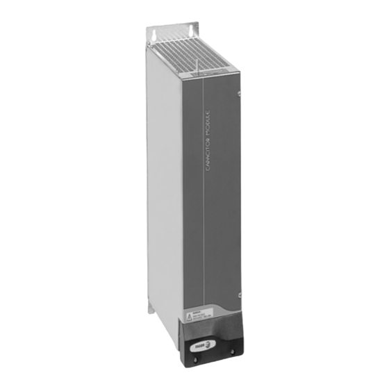
Page 199: Capacitor Module
From the energy point of view, installing a capacitor module is more effi- cient than installing external braking resistors. Capacitor module, CM 1.60. Technical data Module that must be connected in parallel to the power DC bus. FAGOR supplies with each module two plates for connecting them to the DC bus. DANGER HIGH VOLTAGE DISCHARGE TIME >... -
Page 200: Auxiliary Power Supply
Auxiliary modules 4.5 Auxiliary power supply The main purpose of the auxiliary power supply module APS-24 is to gen- erate 24 V DC for the control circuits of the drive modules and of the pow- er supplies that do not integrate the auxiliary power supply (i.e. PS-65A). This voltage is supplied through three identical connectors (X2, X3 and X4) connected in parallel that may be accessed from the face of the mod- ule. - Page 201 Auxiliary modules INFORMATION. In case of micro-surges or total mains power outage, this module guarantees the stability of the 24 V DC to feed the control circuits of the drive modules connected to the bus and maintain it for as long as the emergency stop of the motors lasts, thus stopping the axes in a controlled manner.
- Page 202 Auxiliary modules Connectors The auxiliary power supply APS-24 has the following connectors: INPUT 380-460 Vac. RESET OVER VOLTAGE OVER CURRENT OUTPUT 24 Vdc. +24Vdc. +24Vdc. +24Vdc. DANGER HIGH VOLTAGE DISCHARGE TIME > 4 Min Imax total = 10 A Pmax total = 240 W Note.
- Page 203 Auxiliary modules Status indicator lamps The auxiliary power supply APS-24 has the following indicator lights that inform about its running status. OVER VOLTAGE. Red LED. Output over-voltage. It has exceeded 28 RESET V DC and interrupts its operation. OVER VOLTAGE ...
- Page 204 Auxiliary modules HARDWARE Ref.1310...
-
Page 205: Selecting Criteria
SELECTING CRITERIA 5.1 Selection of the synchronous motor and its associated drive First motor pre-selection F. H5/1 General diagram of a MOTOR - LEADSCREW - TABLE system. The motor selection will depend on the mechanical and dynamic re- sponse characteristics that it must satisfy. Hence, the motor must meet the specifications on torque (Nm), speed, duty cycles or other kind of re- quirements of the motor to be moved. - Page 206 Selection criteria The continuous torque M CONTINUOUS FRICTION WEIGHT CUTTING is due to: • the friction between table with its ways and with the ballscrew M • the weight of the table when not moving horizontally M •...
- Page 207 RPM motor --------------- - is the maximum linear speed the table needs. Select in the characteristics table of FAGOR synchronous motors see “AC synchronous servo motors” manual. FXM/FKM families a motor having: • A stall torque equal to or greater than the calculated continuous torque •...
- Page 208 Selection criteria Second motor pre-selection Calculation of inertia (J) The next step is to calculate the load that the motor has to move when accelerating; that is the moment of inertia of all the elements it moves. Total inertia (from now on inertia ) J is due to the load J and to...
- Page 209 Selection criteria Third motor pre-selection Calculation of the acceleration torque and time The required acceleration torque is determined by the total inertia to be moved and the needed acceleration. The required acceleration is determined by the acceleration time t which is the time estimated for the motor to reach its rated speed from zero rpm.
- Page 210 Selection criteria Summary of the three pre-selections • Maximum speed equal to or greater than calculated value in RPM motor • Stall torque equal to or greater than calculate continuous value M contin- uous • Motor inertia equal to or greater than inertia J LOAD •...
-
Page 211: Asynchronous Spindle Motor And Servo Drive Selection
Selection criteria 5.2 Asynchronous spindle motor and servo drive selection On the spindles of machine tools, it is important to maintain a constant turning speed of the spindle. To control this speed, the drive applies torque to the load according to the characteristics of this load as well as to the adjusted accelerations and decelerations. - Page 212 Selection criteria For lathe work, a cutting blade forces against the part to be machined, while this is turning. See figure F. H5/3 The power required, Pc is calculated as follows: ·d·N (m/min) 1000 ·d·L·v d·L·v (kW) ·...
- Page 213 Selection criteria In the case of a drill, the bit is mounted on the spindle itself and turns with this to drill the material. See figure F. H5/5 The power required in this case Pd may be calculated with the following formula: ·D²·f M·...
- Page 214 Selection criteria The power required in this case P is calculated as follows: S p e e d L o a d ·m ·V (kW) M o t o r 6120· F. H5/7 Frictional load. Required power. ...
- Page 215 Selection criteria T. H5/3 Different accelerations depending on speed. Method Different accelerations depending on speed Control Linear acceleration avoiding abrupt variations in transmitted torque. Emulation of the square sine function for speed by Comment using ramps. Limited acceleration and choke. Choke = (acceleration / t). speed adjust time...
- Page 216 Selection criteria Calculations: 1. With speed between 0 and 1500 rpm. J M N M 2 2 0.13 1500 1 ------ - ------ - -------------------------------- ---------------------- kW 6.41 kW ...
-
Page 217: Drive Selection
Selection criteria 5.3 Drive selection When selecting an FM7 or FM9 motor, see the manual of the AC spindle motor that indicates the drive associated with the selected motor. HARDWARE Ref.1310... -
Page 218: Power Supply Selection
Selection criteria 5.4 Power supply selection Calculation of the power required from the power supply by the synchronous servo motors Initially, considering the mechanical power provided by the motors: T. H5/5 Power supply selection depending on the mechanical power output of the motor. n : Max. - Page 219 Selection criteria Then, depending on the power for S3-5% cycles that could be requested by the drives at any time: T. H5/6 Selection of the power supply depending on the power for S3-5% cycles supplied by the drive for IGBT switching frequencies of 4 kHz and 8 kHz.
- Page 220 Selection criteria Calculation of the power required from the power supply by the asynchronous motors FAGOR asynchronous spindle motor FM7 T. H5/7 Power supply selection when using an FM7 asynchronous spindle motor with E01 and E02 releases.
- Page 221 Selection criteria T. H5/8 Power supply selection when using an FM7 asynchronous spindle motor with E03 release. ASYNCHRONOUS FOR SPINDLE, FM7. Release E03) Max. power consumed by the power supply (kW) Asynchronous for spindle (kW) SUM OF POWER: ...
- Page 222 Selection criteria T. H5/9 Power supply selection when using an FM7 asynchronous spindle motor with HS3 release. ASYNCHRONOUS FOR SPINDLE, FM7. Release HS3 Max. power consumed by the power supply (kW) Asynchronous for spindle (kW) SUM OF POWER: ...
- Page 223 Non-FAGOR asynchronous spindle motor For non-FAGOR asynchronous spindle motors (e.g.: a high speed spin- dle) the previous tables for standard FAGOR motors are not available. To properly calculate the power demanded by the non-FAGOR asynchro- nous spindle from the power supply, it is necessary: ...
- Page 224 Selection criteria Power supply selecting criteria MANDATORY. Note that FM9 spindle motors whose references are FM9-B055- C5C -E01 and FM9-B071-C5C -E01 will necessarily be associated with RPS-75 and RPS-80 power supplies respectively. 1. The power supply module must be capable of supplying the power required by the set of motors and drives connected to it.
- Page 225 Selection criteria 2. The power supply module must be capable of supplying the peak power required by the set of motors and drives connected to it. T. H5/11 Second criteria for selecting the power supply for the whole system. SECOND CRITERIA The power supply module must be capable of supplying the peak power required (depending on the duty cycles) by all the motor-drive sets connected to it.
- Page 226 4. Use the following sheet to calculate the input transformer, and the section of the mains ca- ble . T. H5/13 Power of the input transformer. MAINS VOLTAGE The FAGOR DDS servo drive system requires a mains voltage between 400 and 460 V AC TRANSFORMER A power transformer or auto-transformer must be used 1.05 NOTE.
- Page 227 Selection criteria T. H5/14 Selection of the mains connection cable. POWER CABLE FOR MAINS CONNECTION Vmains from 400 to 460 V AC Rated current through the mains cable MAINS POWER (kW) * 1000 / ( 3 ·...
-
Page 228: Capacitor Module Selection Guide
Selection criteria 5.5 Capacitor module selection guide The CM 1.60 is a capacitor module that increases the electrical capaci- tance of the power bus in 4230 µF. It should be installed on machines with very short duty cycles (very repetitive accelerations and decelerations) and with low braking energy (e.g. -
Page 229: Ballast Resistor Selection Guide
Selection criteria 5.6 Ballast resistor selection guide Calculate the value of: Energy generated by the braking of each system motor. Rms power generated by all braking of all the motors throughout a complete duty cycle. Based on the following formulae: 2... - Page 230 Selection criteria Once the values of Pmx and Pe are calculated, follow these flow charts: NOTE. If you have external resistor ER+TH- / or ER-TH-18/ +FAN, already discontinued, use this diagram to obtain the Ohm values requi- red for each power supply.
- Page 231 Ohm value and greater power. On any compact drive whose reference is SCD...-NR no external Ballast resistor will supplied with the unit. The user will place the order for the ex- ternal resistor required by the application with a FAGOR representative. HARDWARE Ref.1310...
- Page 232 Selection criteria HARDWARE Ref.1310...
-
Page 233: Power Line Connection
Ref.1310 Always connect the power supply of other equipment being installed and run together with the DDS system through a second contactor - KM2 or through auxiliary contacts of the power (main) contactor - KM1 . - Page 234 After the main switch - S1 , place the protection fuses, the differential breaker, the 400/460 V AC transformer (only if necessary), the power con- tactor - KM1 to turn on/off the DDS system and the MAINS FILTER A for electromagnetic disturbances.
-
Page 235: Protection Fuses
DDS system to protect it properly. T. H6/1 Technical data of the fuses to be installed in a DDS system with power supply. - Page 236 Power line connection T. H6/3 Fuses to be installed in mains line depending on the power supply installed. PS-25B4 PS-65A RPS-75 Manufacturer XPS-25 XPS-65 RPS-80 RPS-20 RPS-45 FWH45B RF00-125A XL50F-45A XL50F-125A RF-000-40A RF-000-125A BUSMANN 40FE 100FE 160FE 170M2611 170M1318 170M1319...
-
Page 237: Differential Breaker
INFORMATION. As an alternative, Type A differential breakers may be used with selective switch-off. They are more economical than type B ones and usually valid for DDS systems with a FAGOR filter. The off cur- rent must not be < 500 mA and they will have selecting switch-off. -
Page 238: Isolating Transformer Or Autotransformer
6.4 Isolating transformer or autotransformer When the mains voltage must be isolated or adapted to the levels re- quired by the DDS system, it may be connected through an isolating transformer or an auto-transformer. This element will also help reduce the amount of harmonics on the line although it will not guarantee the com- pliance with the CE regulation. - Page 239 (also called boosting power supply, such as the FAGOR RPS). Remember that these power supplies require chokes installed at the power line input be- cause they are regenerative power supplies.
-
Page 240: Mains Filter
Power line connection 6.5 Mains filter In order for the FAGOR DDS servo drive system to meet the European Directive on Electromagnetic Compatibility 2004/108/CE, a mains filter must be installed against electromagnetic disturbances. INFORMATION. This does not guarantee the compliance with such CE Directive on Electromagnetic Compatibility regarding the machine be- cause it may have other devices that could cause disturbances. -
Page 241: Line Inductance
Power line connection 6.6 Line inductance Line inductance means including chokes on each of the three power lines. Its function is to reduce the harmonics generated in mains. The recommended value is given by the formula: V 0.04 ... -
Page 242: Types Of Mains
We here describe the characteristics and, later on, sample diagrams for a proper installation. Note that the diagrams provided here do not show the main contac- tor - KM1 that must be connected between the transformer or auto- transformer and the DDS servo drive system. HARDWARE Ref.1310... - Page 243 TN-C diagram where the neuter and the ground protection functions are combined in a single conductor throughout the system. HARDWARE INFORMATION. TN type mains are the only ones to which the DDS sys- tem can be connected either directly or through an auto-transformer. Ref.1310 See diagram of figure F.
- Page 244 Power line connection TT type mains Distribution diagram that has a point connected directly to ground. The conductive parts of the installation are connected to this ground point in- dependently from the ground electrode of the power supply system. F.
- Page 245 Power line connection IT type mains Distribution diagram that has no point connected directly to ground. The conductive parts of the installation are connected to ground. In this type of mains, the differential breaker is used assuming that the ca- pacitance of mains with respect to ground is large enough to ensure that a minimum fault current flows with the same magnitude as that of the op- erating differential current assigned.
-
Page 246: Mains Connection Cables
Power line connection 6.8 Mains connection cables For further information on the mains cabling for the DDS system, see chapter 7. CABLES , section 7.1 Mains connection cable. Power sup- ply - mains connection . HARDWARE Ref.1310... -
Page 247: Cables
Previous chapters of this manual already described the cabling of the DDS system for the power lines, feedback, optic fiber of the SERCOS ring or CAN bus connection, RS-232/422 serial line connection, communica- tions etc. -
Page 248: Mains Connection Cable. Power Supply - Mains Connection
Note that compact drives have it integrat- ed into them. The table T. H7/2 shows the mains connection cable supplied by FAGOR and their sales reference is MPC- x . T. H7/2 Range of mains connection cables. -
Page 249: Power Cable. Motor-Drive Connection
7.2 Power cable. Motor-drive connection Table T. H7/4 and table T. H7/5 show the range of power cables supplied by FAGOR to connect a motor and a drive. They are supplied without connectors because the power connector will usually be different de- pending on the motor it will be connected to. - Page 250 Cables Cable MPC- 4xO+(2xO). Mechanical characteristics T. H7/7 Mechanical characteristics of the MPC- x +( x ) cable. Type Shield. It ensures EMC Compatibility. High. Special to be used in cable carrying chains with a bending radius of 10 times the Dmax under dynamic Flexibility conditions and 6 times the Dmax under static conditions.
-
Page 251: Motor Feedback Cables
7.3 Motor feedback cables The attached tables show the range of motor encoder cables supplied by FAGOR to connect the motor feedback and a drive. They are supplied with connectors at both ends (see note below) and their sales reference Motor Ref. - Page 252 Cables EEC-FM7CS- cable T. H7/12 Range of EEC-FM7CS- cables. The number indicates their length in meters including the connector. EEC-FM7CS- 5 EEC-FM7CS-20 EEC-FM7CS-35 EEC-FM7CS-50 EEC-FM7CS-10 EEC-FM7CS-25 EEC-FM7CS-40 EEC-FM7CS-15 EEC-FM7CS-30 EEC-FM7CS-45 For further detail on how to connect the drive, see the manual of the cor- responding motor.
-
Page 253: Direct Feedback Cable
Twisted pairs. Overall shield. Ref.1310 To external absolute Overall shield connected to chassis to the drive - X3 - feedback device (on the sensor side and drive side). F. H7/3 Diagram of the direct feedback cable for the FAGOR absolute linear encod-... - Page 254 Cables External Stegmann sinusoidal encoder FAGOR does not supply the direct feedback cable for connecting an ex- ternal Stegmann sinusoidal encoder with the drive. For this connection, you must know the pinout at the encoder end and match it with the pinout at the drive end.
-
Page 255: Signal Cables For Control And Communications
(X3) and the CNC 8055 (X1, X2, X3 or X4) / 8055i (X10, X11, X12 or X13) / 8065/8070 (LOCAL COUNTER 1/2). The attached ta- bles show this cable supplied by FAGOR to connect the drive and the They are supplied with connectors at both ends and their sales ref- erence is: SEC-HD- ... - Page 256 Cables SERCOS optical fiber Fagor Automation supplies the fiber optic cables for SERCOS communi- cations between the group of drives and the CNC in a ring connection and in lengths ranging from 1 to 100 meters. The cables between drives come with the connectors for each module.
- Page 257 Cables Their sales reference is: SFO-V-FLEX- cable T. H7/20 Range of SFO-V-FLEX- cables. The number indicates their length in meters. SFO-V-FLEX-40 SFO-V-FLEX-60 SFO-V-FLEX-100 SFO-V-FLEX-50 SFO-V-FLEX-75 Mechanical characteristics T. H7/21 Mechanical characteristics of the SFO-V-FLEX- cable. The minimum bending radius will be 60 mm in dynamic Flexibility conditions and 45 in static conditions.
- Page 258 Cables CAN cable Cable supplied by Fagor Automation upon request. It is used to establish communication through a CAN field bus between drives and a master de- vice (CNC, PC, ESA panel, etc.). It consists of a pair of twisted wires with a section of 0.25 mm², overall shield and impedance of 120 .
-
Page 259: Rs232/Rs422 Be Adapter
Cables 7.6 RS232/RS422 BE adapter Before showing other connections, it shows the RS232/RS422 BE adapt- er and the pinout for each end. A port of the adapter Connect the end of the (Sub-D, M25) RS-232 or RS-422 cable to this end of the adapter. -
Page 260: Serial Line
RS-232 or RS-422 serial line with a VT panel from ESA. NOTE. The user is free to use this FAGOR adapter or not. But, it should be used unless indicated otherwise because it makes the connection easier. - Page 261 Cables PC-VT connection using an RS-232 cable (without adapter) RS-232 cable 9-pin Sub-D, type female 25-pin Sub-D, connector type male to the VT to PC connector panel (ESA) F. H7/10 RS-232 serial line connection between a PC and VT from ESA (without adapter).
- Page 262 Cables PC-VT connection using an RS-232 cable (with adapter) to the VT panel 9-pin Sub-D, 9-pin Sub-D, (ESA) type female type female connector connector RS422/RS232 BE RS-232 cable adapter cable F. H7/13 RS-232 serial line connection between a PC and VT from ESA (with adapter).
- Page 263 MSP serial port of the VT and the drive's RS-232 serial port. NOTE. When mentioning a drive, it means any model of the FAGOR catalog, i.e. AXD, SPD, ACD, SCD, MMC and CMC models. MANDATORY. The RS-232 serial line can only be used between the ESA VT and a single drive.
-
Page 264: Serial Line
RS-232 or RS-422 serial line with a VT panel from ESA. NOTE. The user is free to use this FAGOR adapter or not. But, it should be used unless indicated otherwise because it makes the connection a lot easier. - Page 265 Cables RS-422 serial line cable between a VT and several drives (with adap- ter) NOTE. Only for MMC or CMC drives. Port A RS-422 cable Port B RS422/RS232 BE Adapter B port of the adapter Pin-Out of port B (Sub-D, M9) N.C.
- Page 266 Cables HARDWARE Ref.1310...
-
Page 267: Installation
Only qualified personnel may install, set up, repair and maintain this equipment. 8.1 Location The type of considerations to bear in mind when placing the DDS servo drive system and run the cables must be: Environmental Mechanical ... - Page 268 For further detail, see next figure: F. H8/1 Top and bottom clearance when installing the DDS system for easier heat evacuation. MANDATORY. Mount the modular drive of greatest power next to the power supply module and use the same criteria for the rest of the drive modules.
- Page 269 Installation Auxiliary modules Dissipated power APS-24 60 W CM 1.60 It depends on the activation fre- ER+TH-x/x and quency of the Ballast protection ER+TH-18/x+FAN circuit. MAINS FILTER 42A 19 W MAINS FILTER 130A 40 W MAINS FILTER 180A 61 W Modular drives Power dissipated at 4/8 kHz...
- Page 270 Installation Electrical considerations MANDATORY. The electrical installation my comply with standard EN 60204-1. Indications regarding EMC Electromagnetic compatibility is covered by the following standards: T. H8/2 Standards regarding electromagnetic compatibility. EN 61800-3:2004 * Adjustable speed electrical power drive systems- Part 3: EMC requirements and specific test meth- ods.
- Page 271 Installation EMC instructions for equipment installation MANDATORY. • Use galvanized or chromed plates in the installation. • Make the connections with wide contact surfaces for the metal parts. • Remove the paint from contact surfaces. • Try to increase conductivity on two-dimensional contacts. •...
- Page 272 Installation Use equipotential wires in systems with: MANDATORY. • Wide-area installation. • Different voltage sources. • Mains through several buildings reducing the current in the cable shield and the emissions. Connect to ground the electrical cabinet, the door, the mounting plate, with ground straps or cables with a cross section larger than 10 mm²...
- Page 273 U V W U V W L1’ L2’ L3’ MAINS XPS-25 FILTER XPS-65 DIFFERENTIAL BREAKER L1 L2 L3 CH1 CH2 CHANNEL HARDWARE CHOKE XPS-XX F. H8/4 Ref.1310 Cables for connecting the elements of the DDS system with an XPS pow- er supply.
- Page 274 L1 L2 L3 CHANNEL F. H8/5 Cables for connecting the DDS system with an RPS power supply. Ventilation related considerations MANDATORY. The ventilation for the electrical cabinet must be enough to dissipate the heat generated by all the devices and components work- ing inside.
- Page 275 The required power and air flow de- pends on the power installed. nstall the DDS system as far away as possible from air inputs and out- puts. Carry out periodic maintenance on air filters.
-
Page 276: Inductive Components
Installation 8.2 Inductive components Installing the DDS system requires certain precautions regarding the con- nection of the inductive components such as contactors, relays, electro- valves, motor brakes or, in general, any type of coil. Hence: All inductive circuits or components must have their own interference suppressor that must be installed as close as possible to the inductive component. -
Page 277: System Installation
NEVER connect APS-24 modules whose refer- ence is PF 23A or older. With newer references, you may connect the APS-24 module to the power DC bus of the DDS system regardless of the main power supply it may come with. - Page 278 Adjust the modules through the RS-232 serial line using the application for PC (WinDDSSetup). INFORMATION. In order for the FAGOR Servo System to meet the Euro- pean Directive on Electromagnetic Compatibility 2004/108/EC, the mod- ules installation rules must be strictly followed regarding: •...
- Page 279 Installation 8.4 Connection between modules Power bus connection The power bus is connected through the terminals hidden under the cover at the bottom of each module. To do this, use 2 of the 3 plates and the washers and nuts supplied with each module.
- Page 280 To replace a drive module in case of a failure or remove it from the DDS system for inspection, follow these steps to “free” it from the other mod- ules.
- Page 281 Installation Ground connection MANDATORY. It is up to the system integrator to meet all the require- ments of local and national electrical codes as well as all the regulations applicable regarding the grounding of the whole unit. The chassis of each modules must be connected to a single point and from there to the ground terminal of the electrical cabinet.
- Page 282 Installation Internal bus connection To make this connection, join the X1 connectors of each module with the ribbon (flat) cables supplied with each of them as shown in the next figure: F. H8/11 Internal bus connection. HARDWARE Ref.1310...
- Page 283 Installation Connection to the external Ballast resistor The external resistor modules are designed to be installed in the corre- sponding terminals of the power supplies or compact drive modules (with an integrated power supply) in order to dissipate the excess energy gener- ated when braking the servomotors.
- Page 284 Installation Electrical configurations of the resistor with compact drives Configuration Configuration for connecting the for connecting the internal external Ballast resistor Ballast resistor ONTROL ONTROL F. H8/13 Electrical configurations of the Ballast resistor with compact drives. WARNING. Never connect an external resistor in parallel with the internal Ballast resistor.
- Page 285 Installation How to install an external Ballast resistor with internal thermostat and with no fan WARNING. On top of the ER+TH modules, the air temperature can reach values over 120 °C (248 °F). Therefore, the resistor should be mounted away from the rest of the modules or even outside the electrical cabinet, al- ways vertically and away from cables and other temperature sensitive material.
- Page 286 Installation How to install an external Ballast resistor with an external thermo- stat and with no fan WARNING. On top of the ER+TH modules, the air temperature can reach values over 120 °C (248 °F). Therefore, the resistor should be mounted away from the rest of the modules or even outside the electrical cabinet, always vertically and away from cables and other temperature sensitive material.
- Page 287 Installation How to install an external Ballast resistor with internal thermostat and WARNING. Therefore, the resistor should be mounted away from the rest of the modules or even outside the electrical cabinet, always vertically and away from cables and other temperature sensitive material. Always install it vertically Faston type termi- nals for connecting...
- Page 288 Installation How to install two external Ballast resistor in parallel. Diagrams Always install both resistors vertically Diagram for two resistors in parallel with fan and internal thermostat A una toma A una toma 50/60 Hz Axial fan Axial fan 50/60 Hz 220/240 V AC...
- Page 289 On any compact drive whose reference is SCD-NR x.xx no external Ballast resistor will supplied with the unit. The user will place the order for the ex- ternal resistor required by the application with a FAGOR representative. Remember that it must have the same Ohm value as the internal resistor of the module.
- Page 290 INFORMATION. If a fan is required due the conditions of the location where the resistor will be installed, remember that Fagor Automation offers external ballast resistors with fan. See an example with data on the temperatures reached in points of the top of the module and the effect of the fan: T.
- Page 291 WARNING. The 24 V DC can also be used in the circuit of the electrical cabinet, but NEVER TO ACTIVATE THE MOTOR BRAKE! WARNING. The 24 V DC power supply output generated in the FAGOR “POWER SUPPLY MODULE” unit must only be used for the 24 V DC con- trol input.
- Page 292 Installation Connection of the APS-24 power supply Take two mains phases and ground to the input connector X1 of the auxil- iary power supply APS-24. See figure: PS- 65A DRIVES APS 24 Mains (Phoenix, 7.62 mm) 0 V DC +24 V DC (Phoenix, (Phoenix,...
- Page 293 The connection is made between the motor feedback connector and con- nector (X4) of the drive module. For further detail on the cables supplied by FAGOR for connecting the motor feedback, see chapter 7. CABLES . The technical data for the motor feedback device connector is shown in the cor- responding motor manual.
- Page 294 Installation Connection for the digital outputs When the drive outputs are connected to inductive loads, we must protect the optocoupler with circuits such as the ones shown in the next figure: 1N4000 Vbr=2.4 V DC IF=Load AC/DC R ~1 ...
- Page 295 The different drive modules and the CNC are connected through SERCOS connector X6 carried by each drive of the FAGOR catalog (see their front panel) through optic fiber. See chapter 7. CABLES of this manual It is a ring connection where the 16-position rotary switch (0-15) of each drive permits selecting the address of each module integrated in it.
- Page 296 When all these connections have been made, the ring will be closed. See figure F. H8/24 . NOTE. With each drive, FAGOR supplies a fiber optic line to connect it to its adjacent module and, upon request, the rest of the required optical fi- ber.
- Page 297 SERCOS ring is QP11 and every time a speed is selected, this parame- ter is associated the corresponding value. See table T. H8/4 that shows the possible transmission speeds that will be displayed at the drive and chapter 13 of the “dds-software” manual to know the meaning of parameter QP11 HARDWARE F.
- Page 298 Installation Transmission speed changing procedure In an initial state (0 state), the display shows the information that already showed in previous versions (errors, SERCOS phase, etc.). Keeping the “boot” button pressed for 3 seconds (long push) it switches to a new state (state 1) that is used for selecting the communication speed and the display shows the speed currently selected.
- Page 299 QP11 = 8 8 MBd QP11 = 16 16 MBd to be compatible with previous versions of the SERCOS board. See the values that will be assigned to their associated parameter QP11 in chapter 13 of the “dds-software” manual. HARDWARE Ref.1310...
- Page 300 Installation SERCOS connection wih a FAGOR 8055 CNC A drive is connected to a FAGOR 8055 CNC via SERCOS through connec- tor COM1 located on the front panel of the CPU module. See figure CMPCT FLASH COM1...
- Page 301 Installation SERCOS connection with a FAGOR 8055i CNC The SERCOS connection of the FAGOR 8055i CNC will be made through the SERCOS DRIVES connector on the top rear of the module. See fig- ure: OUT IN OUT IN +24V F.
- Page 302 The different drive modules and the CNC are connected through CAN con- nector (X6) carried by each drive of the FAGOR catalog (see their front panel) through the CAN cable. See chapter 7. CABLES in this manual .
- Page 303 Installation ISO GND SHIELD CAN L CAN H SHIELD SHIELD CAN H CAN L SHIELD ISO GND F. H8/33 CAN cable to connect a CNC and two drives. NOTE. Note that the connectors of the intermediate modules (when con- necting several drives in the bus) receive two wires, in each pin of the CAN connector, coming from each adjacent module.
- Page 304 See table T. H8/5 that shows the possi- ble baudrate values that will be shown on the drive display. Chapter 12 of the “dds-software” manual explains the meaning of parameter QP11. “BOOT” BUTTON RS-232 line connector...
- Page 305 Installation Once the display shows the desired speed, apply a long push and QP11 will be assigned its associated value that will be saved into the flash memo- ry of the drive and will reset the drive. F.
- Page 306 CAN connector of the ESA Video terminal. CAN connection with a FAGOR 8055 CNC The FAGOR 8055 CNC is connected to the drives via CAN through con- nector COM1 located on the front panel of the CPU module. See figure:...
- Page 307 Installation CAN connection with a FAGOR 8055i CNC The CAN connection of the FAGOR 8055i CNC will be made through the CAN DRIVES connector on the top rear of the module. See figure: CAN I/Os CAN DRIVES +24V F.
- Page 308 NOTE. The system communication through RS-232/422 is configured us- ing the WinDDSSetup application for PC. See the “communications” tab of the <preferences> menu in chapter 16. WINDDSSETUP of the “dds- software” manual. Particular In order to establish communication via RS-232 serial line, each drive of the system must be differentiated using the 16-position “NODE SELECT”...
- Page 309 Installation RS-232/422 serial line connection with an ESA video terminal The RS-232/422 connection of the ESA terminal with the drives is made through the MSP connector located at the bottom of the VT module. See figure: Bottom view ESA panel (VT 150W) [ Sub-D, F25 ] Sub-D, F25...
- Page 310 Installation RS-232/422 serial line connection with a drive The RS-232/422 connection of the drive (only MMC or CMC models) is made through the X6 connector on the front panel of the module. See fig- ure: U V W NODE SELECT STATUS...
- Page 311 Installation 8.7 Check the installation Check the installation: Mechanical fixtures for the whole system Distances Tighten all the mounting screws with their corresponding tightening torque. Electrical connections and wiring: Connection of protection wires ...
- Page 312 Installation HARDWARE Ref.1310...
- Page 313 FUNCTIONAL SAFETY See section on - SAFETY CONDITIONS - at the beginning of this manual. The references of drive modules certified according to the STO safety function are unmistakably determined in the declaration of conformity and in the TÜV certificate. Both documents may be found at the beginning of this manual.
- Page 314 Functional safety 9.1 STO safety function The STO ( S afe T orque O ff) is the only safety function Fagor Automation drives AXD/SPD offer according to the standard IEC 61800-5-2. This safety function may be used to safely disconnect the motor torque and it is always active.
- Page 315 Functional safety 9.2 Interface SAFE TORQUE OFF SAFE TORQUE OFF DRIVE ENABLE (first channel input) (second channel input) SPEED ENABLE O.K. +24 V DC Aerial male connectors X2 and X7. Mechanical data. NODE AXD/SPD STATUS DISPLAY Connector data Nr of poles (X2/X7) Gap (mm) Min./max.
- Page 316 Functional safety 9.3 Examples Note. These examples use an external safety relay. Example 1. STO (S afe T orque O ff ) safety function with PL d or SIL 2 This STO safety function corresponds to an uncontrolled stop in accor- dance with stop category 0 of IEC 60204-1.
- Page 317 Functional safety Considerations to bear in mind in the previous examples The auxiliary 24 V DC power supply must be independent from the power controlled by external main contactor - KM1. To achieve PL d or SIL 2, the safety controller must check the feed- back of the STO safety function;...
- Page 318 DDS system in general The precautions to bear in mind regarding the installation of Fagor Auto- mation's D igital D rive S ystem are described in the section on - SAFETY CONDITIONS - in this manual.
- Page 319 Functional safety 9.5 Risk analysis The machine manufacturer must run a thorough analysis of the possible risks of the whole system and take the necessary measures to ensure the safety of the machine as a whole. The residual risk of the machine re- maining after carrying out all the protection measures taken.
- Page 320 Functional safety 9.6 Technical data of the safety function Fagor Automation drives AXD/SPD only offer the safety function STO ( S afe T orque O ff) defined according to the standard IEC 61800-5-2. To calculate the P erformance L evel (PL of ISO 13849-1) and/or the S afe-...
- Page 321 Functional safety 9.7 Response time FAGOR recommends measuring the response time of the implemented safety functions. This measurement must be taken from the instant the danger condition takes place (e.g. door opened) to the instant the safety function is executed (e.g.
- Page 322 AXD/SPD drive (pin 2 “Drive Enable” of X2). FAGOR recommends installing a “1 A” slow fuse to limit the input cur- rent through this pin. In the case of the figure where a safety relay has...
- Page 323 Functional safety 9.9 Commissioning Check that each of the two channels of the STO, i.e. - KM1 and Drive En- able, separately, remove motor torque. Also check the feedback of each channel. Document the tests of the safety function on the minutes (record). HARDWARE Ref.1310...
- Page 324 Functional safety 9.10 Maintenance, repair and analyze hazardous events Although it is not required due to its low probability, FAGOR recommends to demand the STO safety function at least once every 24 hours in order to detect possible failures in the STO circuit.
- Page 325 Functional safety 9.11 Decommission and disposal The machine manufacturer must indicate the procedure to be used for de- commissioning the machine. Respect environmental regulations. Observe that the AXD/SPD drive modules do not carry batteries. Bear in mind the storage and shipping requirements when disposing of the AXD/SPD units.
- Page 326 Functional safety HARDWARE Ref.1310...
- Page 327 CONNECTION DIAGRAMS 10.1 SPD modular drive with FM7 asynchronous spindle motor Connection diagram of an SPD modular drive with an FM7 asynchronous spindle motor that has TTL encoder feedback. Digital Spindle Modular Drive Ready made cable to 8055/55i CNC, SEC-HD 1/3/5/10/15/20/25/30/35 SPD 2.50-SI-1 Length in meters;...
- Page 328 Connection diagrams 10.2 AXD modular drive with FKM synchronous axis servo motor Ready made cable EEC-SP 5/10/15/20/25/30/35/40/45/50 Length in meters; including connectors EOC-12 Green E0C-12 Yellow REFCOS Front View REFCOS Blue Purple REFSIN REFSIN Black +485 +485 Brown - 485 -485...
- Page 329 Connection diagrams 10.4 SCD compact drive with FM7 asynchronous spindle motor Connection diagram of an SCD compact drive with an FM7 asyn- Digital Spindle Compact Drive chronous spindle motor that has SCD 1.25-A ... encoder feedback. MPC- 4x... Ready made cable to 8055/55i CNC, SEC-HD 1/3/5/10/15/20/25/30/35 Length in meters;...
- Page 330 Connection diagrams 10.5 ACD compact drive with FKM synchronous axis servo motor Connection diagram of an ACD compact drive with an FKM Digital Axis Compact Drive synchronous axis motor that ACD 1.15 - SI ... has encoder feedback. MPC- 4x...
- Page 331 Connection diagrams 10.6 ACD compact drive with FXM synchronous axis servo motor Connection diagram of an ACD Digital Axis Compact Drive compact drive with an FXM syn- ACD 1.15 - SI ... chronous axis motor that has en- coder feedback.
- Page 332 If the status of each drive is OK and no errors have occurred, each drive closes its DR.OK contact. If the status of all the drives that make up the DDS system is correct and no errors have occurred, each one of them lets the power supply know through the internal bus (only the modular drives).
- Page 333 Connection diagrams NOTE. Observe that a push-button (N.O., N ormally O pen) is included in parallel with the limit switches for disabling (via PLC) the movement of the axes of the machine in the opposite direction. After activating the relay - KA1, its associated contact closes, to allow sup- plying three-phase power to the system by pressing the ON button closing the contactor - KM1.
- Page 334 Connection diagrams A stop may be caused by: opening the main power switch - S1 , one or several fuses have blown or there is simply a power outage while the system is running. The motor brakes with emergency ramps if they were initially set by pa- rameters.
- Page 335 NOTE. The reaction time of a brake integrated into an axis feeding FAGOR motor may vary between 7 ms and 97 ms depending on the mod- MANDATORY. While the brake is locking the vertical axis motor, the motor must be kept with torque.
- Page 336 Connection diagrams BLOCK DIAGRAM OF THE DDS SYSTEM START-UP WITH PS-XX POWER SUPPLIES HARDWARE Ref.1310 F. H10/7 Block diagram of the DDS system start-up with non-regenerative power supplies.
- Page 337 Connection diagrams BLOCK DIAGRAM OF THE DDS SYSTEM START-UP WITH XPS AND RPS POWER SUPPLIES HARDWARE Ref.1310 F. H10/8 Block diagram of the DDS system start-up with regenerative power supplies.
- Page 338 Connection diagrams 10.8 Diagrams with a PS-65A power supply RM-15, (or ER) N.C. Thermal RESISTOR Switch (RM-15) +24 V DC MODULE External Ballast Internal Ballast +24 V DC PS-65A. Power POWER SUPPLY Error Reset System Speed Enable Internal SYSTEM (Phoenix,...
- Page 339 - KM1 is open, the external APS-24 auxiliary power supply remains connected through its connector X1 to feed TO THE POWER CONNECTOR Ref.1310 the control circuits of the drive. PS-65A POWER SUPPLY 3x400-460 VAC F. H10/11 General diagram of a DDS system with a PS-65A power supply.
- Page 340 Connection diagrams 10.9 Diagrams with a PS-25B4 power supply External Ballast TO THE RM-15, ER or ER+TH N.C. Thermal Switch ELECTRICAL RESISTOR +24 V DC (RM-15 or ER+TH-X/X) MANEUVER MODULE Internal Ballast +24 V DC PS-25B4. Error Reset POWER SUPPLY System Speed Enable...
- Page 341 - KM1 is open, the internal auxiliary power supply remains connected through its connector X3 to TO THE POWER CONNECTOR Ref.1310 feed the control circuits of the drive. PS-25B4 POWER SUPPLY 3x400-460 VAC F. H10/14 General diagram of a DDS system with a PS-25B4 power supply.
- Page 342 Connection diagrams 10.10 Diagrams with a XPS power supply RM-15, ER or ER+TH RESISTOR MODULE 10 mm (XPS-25) 50 mm (XPS-65) +24 V DC CHOKE XPS-xx +24 V DC External Ballast OR Internal Ballast Choose either Error Reset configuration, not both.
- Page 343 TO THE POWER CONNECTOR of the XPS remains connected through its connector X3 to feed the XPS-XX POWER SUPPLY Ref.1310 control circuits of the drive. 3x400-460 VAC F. H10/17 General diagram of a DDS system with a XPS power supply.
- Page 344 Connection diagrams 10.11 Diagrams with an RPS-XX power supply IMPORTANT. It is absolutely necessary to short-circuit pins NS1 and NS2 externally with a wire of at least 1 mm² section for the RPS to work. To PLC, To PLC, CNC or CNC or 3x1mm...
- Page 345 Connection diagrams OPERATION DIAGRAM. RPS-XX Important. The relay - KA3 acts simultane- +24VDC ously upon contact KA3,1 to excite the coil of contactor - KM1 and upon the auxiliary contact KA3,2 (see previous figure) associated with the PWN ENABLE (pin 4 of X6) of the RPS power supply.
- Page 346 DR.Z 2x400-460 V AC (Phoenix, 5.08 mm) Chassis FAGOR Notes. Compact modules do not have the System_Speed_Enable signals. In this diagram, in spite of having SERCOS interface, electrical signals are used to activate the enables. F. H10/21 Compact system with SERCOS connection.
- Page 347 (Phoenix, 5.08 mm) 5.08mm) Chassis Chassis FAGOR FAGOR Notes. Compact modules do not have the System_Speed_Enable signals. In this diagram, in spite of having CAN interface, electrical signals are used to activate the enables. F. H10/22 Compact system with CAN connection.
- Page 348 X1 to TO THE POWER CONNECTOR feed the control circuits of the drive. ACD/SCD COMPACT DRIVES HARDWARE 3x400-460 VAC F. H10/24 General diagram of a compact DDS system with SERCOS or CAN connection. Ref.1310...
- Page 349 DRIVE Speed Enable DR.Z OUT2 2.5 Amp OUT2 (F) Fuse +24 V DC COMPACT DRIVE Error Reset MODULE Drive Enable Speed Enable 3x400-460 V AC DR.S 2x400-460 V AC Chassis FAGOR HARDWARE F. H10/25 Mixed system with SERCOS connection. Ref.1310...
- Page 350 COMPACT DRIVE DRIVE Error Reset Error Reset MODULE MODULE Drive Enable Drive Enable Speed Enable Speed Enable 3x400-460 VAC 3x400-460 VAC DR.S DR.S 2x400-460 VAC 2x400-460 VAC Chassis Chassis FAGOR FAGOR HARDWARE F. H10/26 Mixed system with CAN connection. Ref.1310...
- Page 351 Connection diagrams OPERATION DIAGRAM +24VDC Note 1. - KA3 is a relay for a delayed deactivation of contactor - KM1 (t seconds) in order to be able to keep it closed long enough to return to mains (with XPS power supply) the excess energy g e n e r a t e d wh i l e b r a k i n g t h e motor.
- Page 352 Connection diagrams 10.16 Brake connection diagram for synchronous axis servo motors - S1 MECHANICAL MAIN SWITCH 230 VAC FXM MOTOR 24 VAC +24 VDC 0 VDC BRAKE F. H10/28 Connection diagram for the brake of an FXM synchronous servo motor. - S1 MECHANICAL MAIN SWITCH 230 VAC...
- Page 353 2. To brake the motor in a controlled way during a power failure, make sure that 24 V DC will be supplied to contactors - KM1 and - KM2 and relays - KA3 and - KA4. This situation is ensured if you have installed a FAGOR power supply next to an SPD modular drive.
- Page 354 Connection diagrams HARDWARE Ref.1310...
- Page 355 DIMENSIONS When designing and building the electrical cabinet, it is crucial to consider the necessary space to in- clude the modules that will make up the DDS system, auxiliary modules and other elements such as cables and connectors. 11.1 Main modules HARDWARE F.
- Page 356 Dimensions 11.2 Power supply modules HARDWARE F. H11/2 Dimensions of the power supplies. Ref.1310 A. PS-65A, B. PS-25B4, C. XPS-25, D. XPS-65, E. RPS-20, F. RPS-45, G. RPS-75/80.
- Page 357 Dimensions 11.3 Modular drive modules F. H11/3 Dimensions of the modular drives. A. AXD/SPD 1.08/1.15, B. AXD/SPD 1.25/1.35, C. AXD/SPD 2. , D. AXD/SPD 3. . HARDWARE Ref.1310...
- Page 358 Dimensions 11.4 Compact drive modules F. H11/4 Dimensions of the compact drives. A. ACD/SCD 1. , B. CMC 1. , C. ACD/SCD 2. , D. CMC 2. . HARDWARE Ref.1310...
- Page 359 Dimensions 11.5 Mains filter 50 mm 50 mm MAINS FILTER 42A PS-25B4, XPS-25, RPS-20 ACD/SCD/CMC 1.xx, ACD/SCD/CMC 2.xx MAINS FILTER 130A PS-65A, XPS-65, RPS-45, RPS-75 MAINS FILTER 180A RPS-80 F. H11/5 MAINS FILTER A . T. H11/1 Dimensions.
- Page 360 Dimensions 11.6 XPS chokes CHOKE XPS-65 CHOKE XPS-25 (DISCONTINUED) Ø E CHOKE XPS-65-A Ø E BASE AREA F. H11/6 A. PS-25 CHOKE. B. XPS-65 CHOKE. C. XPS-65-A CHOKE. T. H11/2 Dimensions. CHOKE XPS-25 CHOKE XPS-65 CHOKE XPS-65-A (DISCONTINUED) (NEW) Units...
- Page 361 Dimensions 11.7 RPS chokes RPS-75-3 CHOKE RPS-45 CHOKE RPS-20 CHOKE F. H11/7 Chokes RPS-75-3, RPS-45 and RPS-20. T. H11/3 Dimensions. CHOKE RPS-20 CHOKE RPS-45 RPS-75-3 CHOKE inches inches inches 12.99 12.99 14.96 6.88 6.88 9.25 5.35 5.35 5.98 5.90 5.90...
- Page 362 Dimensions 11.8 External Ballast resistors with external thermostat Ø6.2x4 THERMO-SWITCH 160°C 80 ÷ 84 71 95 FAST ON 6.3 mm F. H11/8 External Ballast resistors with external thermostat. T. H11/4 Dimensions. With external ER+TH-43/350 ER+TH-24/750 ER+TH-24/1100 thermostat Units inches inches...
- Page 363 Dimensions 11.9 External Ballast resistors with internal thermostat Ø6.5x11 2.5 mm² THERMOSTAT OUT CABLES 2.5 mm² F. H11/9 External Ballast resistor with internal thermostat. T. H11/6 Dimensions. With internal ER+TH-18/1800 ER+TH-18/2200 thermostat Units inches inches 4.72 7.48 1.57 2.63 14.96...
- Page 364 Dimensions 11.10 External Ballast resistors with external thermostat & cooling fan F. H11/10 External Ballast resistors with external thermostat and fan. T. H11/7 Dimensions. With external ER+TH- ER+TH- ER+TH- thermostat & fan 18/1000+FAN 18/1500+FAN 18/2000+FAN Units inches inches inches 6.88...
- Page 365 SALES REFERENCES This chapter indicates the sales references of all FAGOR products. It refers to: Synchronous servo motors FXM, FKM Asynchronous servo motors FM7, FM9 Modular drives AXD, SPD Compact drives ACD, SCD MC drives MMC, CMC Power supply module...
- Page 366 Sales references 12.1 References of synchronous servo motors Sales reference of the synchronous servo motors, FXM. MOTOR SERIES SIZE 1, 3, 5, 7 LENGTH 1, 2, 3, 4, 5, 6, 7, 8 RATED 12 1200 rev/min 30 3000 rev/min SPEED 20 2000 rev/min 40 4000 rev/min...
- Page 367 Sales references Sales reference of the synchronous servo motors, FKM. FAGOR SYNCHRONOUS MOTOR SIZE 2, 4, 6 LENGTH 1, 2, 4, 6 2 , 3, 4, 5 20 2000 rev/min 45 4500 rev/min RATED 30 3000 rev/min...
- Page 368 Sales references 12.2 References of asynchronous motors Sales reference of the asynchronous motors, FM7. FM7- - - E0 FAGOR M7 MOTOR BASE SPEED (SINGLE WINDING) 1500 REV/MIN 1000 REV/MIN 500 REV/MIN 1250 REV/MIN POWER (S1 DUTY CYCLE).
- Page 369 Sales references 12.3 References of modular drives Sales reference of the modular drives for synchronous axis servo motors, AXD. AXD 1 . 08 - C0 - 2 - B MODULAR AXIS DRIVE, AXD Example: AXIS DRIVE SIZE 77 mm (08/15/25/35) Width (mm)
- Page 370 Sales references 12.4 References of compact drives Sales reference of the compact drives for synchronous axis servo mo- tors, ACD. AXIS COMPACT DRIVE, ACD ACD 2 . 50 - C0 - 2 - B Example: AXIS COMPACT DRIVE SIZE 77 mm (08/15/25) Width (mm)
- Page 371 Sales references 12.5 References of positioning drives Sales reference of the modular positioning drive for synchronous axis mo- tors, MMC. MODULAR POSITIONING MMC 1 . 25 - C0 - D2. D1 - 1 - 0 - B DRIVE, MMC Example: MODULAR MOTION CONTROL...
- Page 372 Sales references 12.6 Power supply references Sales reference of the power supplies, PS-65A. PS - 65A POWER SUPPLY, PS Example: POWER SUPPLY (Mains voltage of 400 - 460 V AC) POWER (power, rated current) 65A (65 kW, 120 A) F.
- Page 373 Sales references 12.7 References of other elements Sales reference of accessory modules. MAINS FILTER 42A ACCESORY MODULES Example: FAGOR MAINS FILTER MAINS FILTER MAX. CURRENT MAINS FILTER 42 A MAINS FILTER 130A 130 A MAINS FILTER 180A...
- Page 374 LENGTH (m) 3, 5, 10, 15, 20, 25, 30, 35, 40, 45, 50 Example: EEC-FM7CS - 20 EEC-FM7CS ENCODER EXTENSION CABLE - FAGOR MOTOR 7 C AXIS SHIELD LENGTH (m) 5, 10, 15, 20, 25, 30, 35, 40, 45, 50 F.
- Page 375 Sales references Sales reference of the SERCOS interface cable Example: SFO - 2 FIBER OPTIC LINES (Polymer core) SERCOS FIBER OPTIC LENGTH (m) 1, 2, 3, 5, 7, 10, 12 Example: SFO - FLEX - 15 FIBER OPTIC LINES (Polymer core) SERCOS FIBER OPTIC - FLEX SFO - FLEX...
- Page 376 Sales references 12.9 Order example FAGOR AUTOMATION S. COOP. LTDA UNIT REFERENCE DESCRIPTION PRICE PRICE US $ US $ FXM 33.30A.R0.000 Axis motor 5,77 Nm, 3.000 with resolver FXM 33.30A.R0.000 Axis motor 5,77 Nm, 3.000 with resolver...
- Page 377 Sales references 12.10 Module identification Each electronic module is identified by its characteristics plate. It indi- cates the model and its main technical characteristics. WARNING. The user must make sure that the references indicated on the packing list of the order match those supplied by each module on its characteristics plate before making any connection to avoid any possible shipping errors.
- Page 378 Sales references HARDWARE Ref.1310...
- Page 379 400-460 V AC (50/60 Hz). Their identification comes on the label that each of these module has. Elements for 380 V AC Elements for 400- 460 V AC Fagor Automation, Fagor Automation, S.Coop.(Spain) S.Coop.(Spain) MODEL...
- Page 380 Compatibility 13.3 Module replacement Replacing 380 V AC module with a new 460 V AC module involves: Drive MSC 12A or later. Auxiliary power supply APS 24 PF 05A and later. Capacitor module CM 1.60 (version [CAP 00A] [VAR 02A] and later). NOTE.
- Page 381 Compatibility 13.6 VECON-3 board This board replaces the VECON-2 board. Version of the VECON-3 board Software version VEC 01A and later 06.18 and later NOTE. It is possible but not recommended to have the same machine with several units where one controls its motor with a 04.xx version and hardware with VECON another one that controls its motor with a 05.xx version and hardware with VECON-2 and a third one that controls its mo- tor with 06.18 version or later and VECON-3 hardware.
- Page 382 13.12 CAN board Although this board was already recognized on FAGOR drives since soft- ware version 07.0x, now when using a FAGOR drive that has a CAN communication board, always install software version 08.0x. INFORMATION. Remember that all the modules (CNC included) must be set with the same transmission speed.
- Page 383 Compatibility 13.15 CAPMOTOR-2 board and type of feedback Feedback device type Motor feedback board Resolver CAPMOTOR-1 Stegmann encóder CAPMOTOR-1, CAPMOTOR-2 Encoder with square signals U, V and W CAPMOTOR-1, CAPMOTOR-2 Encoder with C and D signals CAPMOTOR-1, CAPMOTOR-2 EnDat with incremental A and B signals CAPMOTOR-2 CAPMOTOR-2 INFORMATION.
- Page 384 Compatibility HARDWARE Ref.1310...
- Page 386 FAGOR AUTOMATION Fagor Automation S. Coop. Bº San Andrés, 19 - Apdo. 144 E-20500 Arrasate-Mondragón, Spain Tel: +34 943 719 200 +34 943 039 800 Fax: +34 943 791 712 E-mail: info@fagorautomation.es www.fagorautomation.com...
Need help?
Do you have a question about the DDS and is the answer not in the manual?
Questions and answers