Table of Contents
Advertisement
CP1
MOVING MAGNET PHONO PREAMPLIFIER
CP1 Specifications
Max Power consumption
Nominal output
THD 20Hz-20KHz
Signal to noise ratio using Audio Precision
RIAA-1 with grounded inputs
Input capacitance
Crosstalk @ 20KHz
Gain @ 1KHz
Sensitivity for norminal output
RIAA curve accuracy
Input imprdance
Overload margin
Dimensions(H x W x D)
Weight
CP2 Specifications
Max Power consumption
Nominal output
THD 20Hz-20KHz
Signal to noise ratio using Audio Precision
RIAA-1 with grounded inputs
Input capacitance
Crosstalk @ 20KHz
Gain @ 1KHz
Sensitivity for norminal output
RIAA curve accuracy
Input imprdance
Overload margin
Dimensions(H x W x D)
Weight
Service Manual
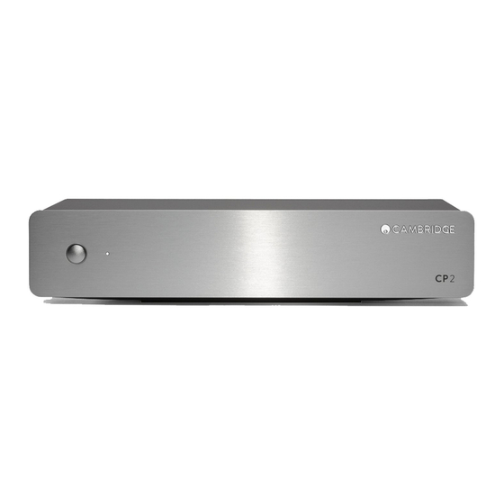
CP2
MOVING MAGNET & MOVING COIL PHONO PREAMPLIFIER
CP1 Technical specifications
5W
300mV
<0.009%
>85dB
220pF
>76dB
39dB
3.35mV
<+/- 0.65dB 25hz-20KHz
47k Ohm
>30dB
46 x 215 x 133 (1.8 x 8.5 x 5.2")
0.8kg (1.8lbs)
CP2 Technical specifications
5W
300mV
<0.009%
>86dB
220pF
>83dB
39dB
3.35mV
<+/- 0.3dB
47k Ohm
>30dB
46 x 215 x 133 (1.8 x 8.5 x 5.2")
0.9kg (2.0lbs)
Issue date: Feb 2016
version 1.0
Advertisement
Table of Contents

Subscribe to Our Youtube Channel
Summary of Contents for CAMBRIDGE CP1
- Page 1 Issue date: Feb 2016 version 1.0 Service Manual MOVING MAGNET & MOVING COIL PHONO PREAMPLIFIER MOVING MAGNET PHONO PREAMPLIFIER CP1 Specifications CP1 Technical specifications Max Power consumption Nominal output 300mV THD 20Hz-20KHz <0.009% Signal to noise ratio using Audio Precision >85dB...
-
Page 2: Table Of Contents
This guide is designed to make installing and using this product as easy as possible. Information in this document has been carefully checked for accuracy at the time of printing; however, Cambridge Audio’s policy is one of continuous improvement, therefore design and specifications are subject to change without prior notice. - Page 3 For continued compliance only plug having been damaged, liquid has been spilled or objects have fallen into Cambridge Audio accessories should be used with this product and servicing must the apparatus, the apparatus has been exposed to rain or moisture, does not be referred to qualified service personnel.
- Page 4 Service Manual CP1/CP2 Rear panel connections Designed & Engineered in Britain Assembled in China Turntable Ground 0.5 A Cartridge Type Subsonic Filter Balance Output 1. MC input sockets (CP2 only) Front panel control If your turntable uses a moving coil cartridge, connect outputs here (0.5-1mV, with 100 ohm, 220pF loading).
- Page 5 Connections...
- Page 6 Service Manual CP1/CP2 Troubleshooting There is no power Ensure the power supply is connected securely to the unit. Ensure the power supply is fully inserted into the mains socket and is switched There is no sound Make sure the unit is plugged in.
-
Page 7: Cp1 Main Assembly
CP1 main assembly Exploded drawing view ref Description Service part (order ref) front panel and CA foil badge 1 + 2 Azur range lightguide for 1 LED CP1 Main PCBA PHT001 9mm push switch button in aluminum screw M3 X 4 pozi pan washer mc... -
Page 8: Cp2 Main Assembly
Service Manual CP1/CP2 CP2 main assembly Exploded drawing view ref Description Service part (order ref) 1 + 2 front panel and CA foil badge Azur range lightguide for 1 LED CP2 Main PCBA PHT002 9mm push switch button in aluminum... -
Page 9: Cp Package Assembly
CP package assembly Exploded drawing view ref Description Service part (order ref) main assembly black woven bag packaging 4 + 5 CP1/2 EPE End Left & Right PHT004 UK PSU with ferrite PY867 EU PSU with ferrite PY912 CU PSU with ferrite... -
Page 10: Cp1 Phono Stage Main Pcb - Schematic
Service Manual CP1/CP2 CP1 PHONO STAGE MAIN PCB - Schematic... -
Page 11: Cp2 Phono Stage Main Pcb - Schematic
CP2 PHONO STAGE MAIN PCB - Schematic... -
Page 12: Cp1 Pcb Bottom Layer - Gerber
Service Manual CP1/CP2 CP1 PCB Bottom layer - Gerber... -
Page 13: Cp1 Pcb Top Layer - Gerber
CP1 PCB Top layer - Gerber... -
Page 14: Cp2 Pcb Bottom Layer - Gerber
Service Manual CP1/CP2 CP2 PCB Bottom layer - Gerber... -
Page 15: Cp2 Pcb Top Layer - Gerber
CP2 PCB Top layer - Gerber CAM350 PRO V 7.5.1 : Wed Jan 27 16:11:06 2016 - (Untitled) -
Page 16: Cp1 Bom
Service Manual CP1/CP2 CP1 Bom Service part (order Value Description/Type Component Ident ManPN Tolerance PackageInfo NOTES ref) RESISTORS 1/4W Metal Film R23, R35 10mm Pitch use local source 1/4W Metal Film R25, R37 10mm Pitch use local source 1/8W Metal Film 7.5mm Pitch... - Page 17 3 Way Straight Header LHE PHB A2005-WV03 2mm Pitch DIODES White L-132X-CW896 For Cable Assembly. 400V 1A Rectifier D2-D6, D8-D9, D13 1N4004 DO41 use local source 75V 150mA Signal Diode 1N4148 D035 use local source INTEGRATED CIRCUITS 18V 1A Regulator 7818 Through Hole -18V 1A...
-
Page 18: Cp2 Bom
Service Manual CP1/CP2 CP2 Bom Service part (order ref) Value Description/Type Component Ident ManPN Tolerance PackageInfo NOTES RESISTORS 1/8W Metal Film R5-R6, R21, R23, R34-R35 7.5mm Pitch use local source 1/4W Metal Film 10mm Pitch use local source 100R 1/4W Metal Film... - Page 19 DC Jack RDC-020-14A PY874 Gold plated, From data 2 Way Horizontal RCA CN2-CN4 Through Hole sheet ‘A’ socket WHITE ‘B’ socket RED inserts 2 Way Straight Header LHE XHB A2502-WV02 2.5mm Pitch 3 Way Straight Header LHE PHB A2005-WV03 2mm Pitch LHE XHB A2502-H02 (Header) 2.5mm with cable...
-
Page 20: Ic Pins
Main PCB CP1 / CP2 - 7818 (U1) CP1 / CP2 - 7918 (U2) CP1 - NE5532 (U3 & U4 & U7) CP2 - NE5532 (U3, U4, U5 & U6 & U7) CP1 - 2SA970GR (Q1, 2, 3, 4) CP2 - 2SA970GR (Q1, 2, 3, 4, 5, 6, 7, 8, 10, 11, 12, 13, 14,...


Need help?
Do you have a question about the CP1 and is the answer not in the manual?
Questions and answers