Table of Contents
Advertisement
Quick Links
The CED 1902 Mk IV Owners Handbook
Copyright Cambridge Electronic Design Limited 2017
Neither the whole nor any part of the information contained in,
or the product described in, this guide may be adapted or
reproduced in any material form except with the prior written
approval of Cambridge Electronic Design Limited.
1st edition (1.0)
2nd edition (1.5)
3rd edition (2.0)
4th edition (2.1)
5th edition (3.0)
6th edition (3.1)
7th edition (3.2)
8th edition (3.3)
9th edition (3.4)
Published by:
Cambridge Electronic Design Limited
Technical Centre
139 Cambridge Road
Milton
Cambridge
CB24 6AZ
UK
Telephone:
USA & Canada Toll Free
Web:
Email:
Trademarks and Tradenames used in this guide are
acknowledged to be the Trademarks and Tradenames of their
respective Companies and Corporations.
October 1991
February 1992
March 1997
September 1997
May 2006
May 2008
July 2012
August 2014
May 2017
+44 (0)1223 420186
1-800-345-7794
www.ced.co.uk
info@ced.co.uk
i
Advertisement
Table of Contents

Related Manuals for CAMBRIDGE CED 1902


Summary of Contents for CAMBRIDGE CED 1902
- Page 1 The CED 1902 Mk IV Owners Handbook Copyright Cambridge Electronic Design Limited 2017 Neither the whole nor any part of the information contained in, or the product described in, this guide may be adapted or reproduced in any material form except with the prior written approval of Cambridge Electronic Design Limited.
-
Page 2: Table Of Contents
Table of Contents Preface Publishing information ..............i Table of contents ................ ii Life support ................. v Potential for Radio/Television Interference (USA only) .... v Storage and operating environment ........... vi Protection ................... vi Typographic conventions ............vii Use of symbols ................. vii Installation Introduction ................. -
Page 3: Table Of Contents
Table of Contents The hardware Physical construction ..............13 Installations with multiple 1902s ........13 Rack mount installations ..........13 Using a USB port ..............13 Channel numbers and how to set them ........14 1902 communication configuration ......... 14 Cable connections .............. - Page 4 Table of contents Details of Basic mode of operation ............34 Multiple independent channels ..........35 operation Multi-channel configurations and the1902 input buffer ... 36 1902 input clamp option ............41 Use of the notch filter ............... 43 Theory of electrical isolation ............ 44 Inside the 1902 Cleaning the 1902 ..............
-
Page 5: Life Support
Preface CED products are not authorized for use as critical Life support components in life support systems without the express written approval of the chairman of the board of directors of CED. Life support systems in this context are systems which support or sustain life, and whose failure to perform, when properly used in accordance with instructions for use provided, can be reasonably expected to result in a significant injury to the user. -
Page 6: Storage And Operating Environment
Preface Storage and The storage and operating environment for a 1902 must not exceed the temperature range 0° to +50° Celsius, in conditions operating of non-condensing humidity which should not exceed 95% environment saturation, in an atmospheric pressure range of 500 hPa to 1060 hPa. -
Page 7: Typographic Conventions
This symbol is used on the power supply to show that the outputs are DC only. The CED 1902 is subject to the EU WEEE regulations and may be returned to CED Ltd. for recycling. Observe precautions against electrostatic discharge. -
Page 9: Installation Introduction
Installation Introduction This section will guide you through the installation of your CED 1902 Mk IV isolated pre-amplifier. This involves loading the operating software and running an initial confidence check. Checklist The installation kit for your 1902 comprises: • One or more 1902s, either free-standing or rack-mount •... -
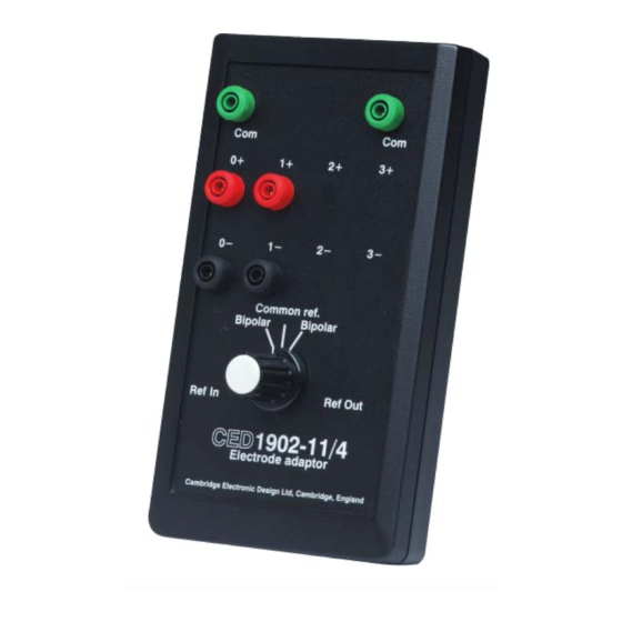
Page 10: The Electrode Box
Installation The Electrode Box The CED1902-11 family comprises optional electrode adaptor boxes that plug into the electrode input sockets of CED 1902 isolation amplifiers. There are four variants of the smaller box: • CED1902-11-2 2 channel (bipolar) • CED1902-11-2B 2 channel (bipolar or common-reference) •... -
Page 11: The Active Head Stage
Note that the buffer connectors are inoperative unless the correct output lead (usually channel 0) is connected to a CED 1902 fitted with the buffer option. For details of common- reference operation using a buffer, see page 36. The 16-channel boxes are available with either 16 signal electrode inputs plus common reference or 16 electrode pairs plus 4 buffer connections. - Page 12 Installation The External Clamp This four-channel device can be used with any amplifier to prevent input saturation, as for instance when high voltages or intense magnetic fields are used as stimuli. On receipt of a TTL signal from external trigger equipment it clamps incoming electrode signals for...
-
Page 13: Installing The 1902 Software
Installation Installing the To install the 1902 operating software, autorun the 1902 Support CDROM supplied with the hardware. This should be 1902 software completely automatic under any version of Windows. It will install Try1902, a diagnostic and calibration program. It will also install the 1902 Control Panel, which can be opened by the user to run the 1902 in stand-alone mode. - Page 14 Installation Try1902 with Trigger test prompt Trigger test Pressing opens a small window that invites you to Trigger test test the trigger inputs with a signal generator and oscilloscope. However, just toggling the two radio buttons will change which of the yellow LEDs is lit on the front panel.
-
Page 15: General Machine Control
General information Machine control In equipment used in research and industry, it is highly desirable that all functions of instrumentation are readable and controllable by computer. The 1902 achieves this by one of the most universal means: the RS232 serial line, or else an RS232 virtual port implemented on a USB adaptor. -
Page 16: Signal Input To The 1902
General information Signal input to To amplify signals with the 1902, you must first the 1902 select the input source and mode of operation. sources transducer isolated amplifier. You cannot use both at once. The transducer has four input modes; the isolated amplifier operates either normally, i.e. - Page 17 General information Input mode table The input modes are tabulated below. For the pinout of the transducer and isolation amplifier sockets, see pages 27 and 28. For more on the fundamentals of differential input, see page 34. Note that, when selecting isolated input, ‘EEG’ is taken to include ECG, EMG, etc.
-
Page 18: 1902 Functional Organization
General information 1902 functional To the user, the 1902 comprises two completely separate functional blocks: the waveform signal conditioner and the organization trigger generator. The waveform The waveform conditioner provides one channel of output, with conditioner the input selected via software from a range of input connections. - Page 19 General information Waveform signal flow in the 1902, detailing digital filtering subsystem...
-
Page 20: Features Seen By The User
General information Features seen Features of the 1902, all selected by program control, are: • Differential or single-ended transducer waveform inputs by the user (non-isolated, not for human subjects) • Optional isolated EEG electrode input • Optional input clamping with EEG input •... -
Page 21: The Hardware
The hardware Physical The 1902 is built on a multilayer printed circuit motherboard, to which a daughterboard may be attached to provide one of the construction various isolation options. This is contained in a two-part folded- steel inner can that provides electromagnetic containment. This assembly is mounted in the outer case, also of folded steel, that provides mechanical protection. -
Page 22: Channel Numbers And How To Set Them
The hardware Channel Wherever there are multiple 1902s, the software uses channel numbers to identify which 1902 is being addressed. Up to numbers and thirty-two channels can be set. In the 1902 Mk IV, channel how to set them numbers 0 - 15 are set by a sixteen-way rotary switch, accessed through a hole in the back panel. - Page 23 The hardware 1902 communications dialog box COM port for 1902 This sets the com port (serial line) used to communicate with communications your 1902s. Try1902 will set this field automatically so you should not need to change this. First 1902 channel This sets the channel number used to start the search for 1902s.
-
Page 24: Cable Connections
The hardware Cable The 1902 needs both power and RS232 cables to be connected; it will not function usefully without RS232 control, although, connections once the 1902 has been set up and is working properly, the RS232 cable can be removed. The two cables are applied to connectors on the rear panel. -
Page 25: Electrode Cables
The hardware Electrode cables When specified, the EEG (or ECG) electrode inputs will normally be routed through the CED1902-11 Electrode Box (see page 2), which accepts standard 1.5mm (optionally 2mm) safety plugs, and connects to the 1902s via a 6-pin DIN plugs. Alternatively, users may wire the 6-pin DIN plug supplied with the 1902 to their own requirements. -
Page 26: Firmware - The 1902 Flash Rom
The hardware Firmware – the Because the 1902 has so many user-specified options (e.g. choice of front end, high-pass and low-pass filter values, notch 1902 flash ROM filter frequency), an internal read-only memory is provided to hold the characteristics of the options fitted and suitable names (in English) for these options. - Page 27 The hardware Isolated Transducer Trigger Amplifier electrode Trigger inputs input input output output Trigger gate (above) Overload Power Trigger signal (below) indicators indicator Front panel features Rear panel features CE & WEEE RS232 Power inlet Serial number symbols 16-position port position channel...
-
Page 28: Software Supplied With The 1902
Application software Software The 1902 is supplied with Try1902, a test and calibration program, which is referred to throughout this manual. Also supplied with the supplied is Ctl1902, a stand-alone applet for users who wish to 1902 run the 1902 as a simple electronic box. In effect, it supplies the knobs and switches of a logical front panel. - Page 29 Application software 1902 Stand-alone Control Panel Low-pass & For digital filters, the corner frequencies are selected from high-pass filters dropdown lists, or users may type in their own values. They can also select slope (2-pole or 3-pole) and filter type (Bessel or Butterworth).
-
Page 30: The Control Panel With Ced Applications
Application software Trigger This toggles between the two trigger inputs, which are functionally identical. A check box can set triggering to occur on the falling edge. (In previous versions of the 1902 only the rising edge could be used.) Unchecking Trigger 1 sets Trigger 2;... -
Page 31: Running The 1902 From Spike2
Application software Running the Spike2 is optimized for the analysis and recording of continuous data, possibly on many channels. Analysis of EEGs during 1902 from Spike2 sleep would be a typical task involving 1902s. All controls remain accessible during data sampling, but, if offset and gain are altered, the last settings are recorded as the offset and gain of the entire data. -
Page 32: Running The 1902 From Signal
Application software Running the Signal is optimized for the analysis of sweep based information, where a sequence of data is recorded repetitively, often 1902 from Signal synchronized to a repeated stimulus. The classic example of this, and one for which a 1902 is ideal, is evoked-response recording;... -
Page 33: Main Amplifier
Electrical specification Main amplifier The main amplifier comprises a programmable-gain amplifier, a selectable mains notch filter, a programmable selection of low- pass and high-pass filters (analogue or digital), and programmable selection of input sources. The output of the amplifier is through a standard coaxial BNC socket. Bandwidth (with analogue filters) DC to 50 kHz (-3dB) in DC mode 0.16 Hz to 50 kHz in AC mode... -
Page 34: Isolation Pre-Amplifier
Electrical specification Isolation A daughterboard option provides the 1902 with a medical- specification isolation pre-amplifier and associated isolated pre-amplifier power supply. This amplifier can be DC blocked, with a corner frequency of 0.16 Hz. Any resistive electrode balancing network is expected to be external to this unit. Input impedance 10 GOhm Input bias current at 25ºC... -
Page 35: Isolated Input
Electrical specification Note: wire colours The ‘Wire colour’ columns in the tables below are for your & socket drawings convenience if you have to make up cables. All 1902 sockets are drawn as the user sees them, i.e. viewed from outside. This is also the view of the backs of their mating plugs as seen while wiring them up! Isolated input... -
Page 36: Transducer Input
Electrical specification Transducer input The 1902 transducer input is an 8-pin DIN socket. Input is inherently differential; for single-ended use, the inverting input is grounded. The main amplifier offsetting DAC is brought out, and may be used as a simple programmable signal source when the waveform conditioner is not required. -
Page 37: Bridge Transducers
Electrical specification Bridge transducers The differential input is connected to a force or pressure transducer, or to a strain gauge. The 1902 can provide the voltage excitation needed. For half-bridge types, binding adaptors must be used to complete the bridge. Single-ended Single-ended transducers should be connected between the +ve transducers... -
Page 38: Trigger Circuit
Electrical specification Trigger circuit The trigger circuit accepts signals from high-impedance sources that cannot drive TTL inputs, such as sensors; it can also be wired to a switch. Trigger connections are made to two mini- DIN sockets on the front panel, one of which will always be active, as shown by its yellow Gate LED. -
Page 39: Wiring Switches
Electrical specification Wiring switches To use a switch that is normally open as a trigger source, connect pins 1 and 4 to one contact, and pin 3 to the other. Connect the screen to the switch body. Closing the switch raises the input from 0 V to 2.5 V. -
Page 40: Rs232 Cable
Electrical specification RS232 port The RS232 port is a standard 9-pin D plug. The functions DSR, CD, and RTS are connected together within the 1902 case so that a simple pin-to-pin cable can be used. The RS232 serial- line cable provided with the 1902 has a 9-way D-type socket at each end, suitable for AT and ATX chassis PCs. -
Page 41: Power Supply
Electrical specification Power supply The 1902 must be powered from a CED-approved power supply if it is to meet the EN 60601-1-1:2000 safety and EN 60601-1-2:2001 EMC standards. The Powerbox™ model PMP55-32-J12 is the current (April 2008) approved supply. Mains electricity This power supply accepts mains voltages from 100 V AC to 240 V AC at frequencies from 50 Hz to 60 Hz, without needing adjustment by the user. -
Page 42: Details Of Operation
Details of operation Basic mode of The simplest method of acquiring an electrophysiological signal with a 1902 is the “Isolated EEG” mode of Spike2, using a operation bipolar electrode configuration. This involves three wires: two as a differential signal input, and a common lead to provide a return path for the very small input bias currents. -
Page 43: Multiple Independent Channels
Details of operation Multiple The 1902 electrode inputs are inherently differential; they will reject a signal that is common to both electrodes. This section independent describes two or more independent differential inputs. Later channels sections will discuss multiple electrode input where there is a common, shared reference. -
Page 44: Multi-Channel Configurations And The1902 Input Buffer
Details of operation Multi-channel The input buffer option (CED1902-4-B) is used in multi- channel configurations where a shared reference potential is configurations required. The option is completely housed inside one of the and the1902 boxes (usually channel 0) of a multi-channel configuration. It input buffer uses spare pins on the isolation input connector to take an input signal in, buffer it and feed it back out. - Page 45 Details of operation Impedance The table shows the calculated degradation of CMRR with mismatch impedance mismatch. Note how an initial small mismatch causes the steepest fall-off in performance. Impedance mismatch (kOhm) CMRR @ 50Hz (dB) >120 Shared electrodes The diagram below shows the situation when two channels are used, with a shared reference electrode.
- Page 46 Details of operation Independent The diagram on the left shows a multi-channel 1902 setup where each channel has separate +ve and −ve electrodes. Each electrode pairs channel produces an independent measurement of the potential difference between the electrodes associated with that channel. There is one common electrode providing the bias current return path.
- Page 47 Details of operation Advantages of The table shows the calculated degradation of CMRR with using a buffer input loading. It can be seen that the buffer circuit has clear advantages in multi-channel configurations. CMRR @ 50Hz (dB) Number of inputs Without buffer With buffer >120...
- Page 48 Details of operation The Active Head As mentioned above, common-mode rejection is a major element in noise reduction (see page 36.) This is because many Stage forms of noise, mains interference in particular, are picked up equally by both leads. Common-mode rejection is essentially a DC phenomenon, but will apply to AC signals provided there is no phase shift between the electrodes.
-
Page 49: 1902 Input Clamp Option
Details of operation 1902 input clamp The input clamp option (CED1902-4-C) is designed for use with triggered stimulation of a subject, where the stimulus option would otherwise overload the isolation amplifier input. Such overloads may not be electrically damaging, but the amplifier can take several seconds to recover afterwards, making it difficult to measure fast responses to the stimulus. - Page 50 Details of operation Details of operation The timing unit can generate pulses in the range 0.5 to 14 milliseconds, the length being determined by the input source selected by software. On receipt of the selected edge on the input, the timing circuit generates a pulse of the Trigger 2 selected length.
-
Page 51: Use Of The Notch Filter
Details of operation Clamping before stimulus The 1902 incorporates a mains-frequency notch filter, set at Use of the time of manufacture to be either 50 Hz or 60 Hz, depending on notch filter the country of destination. It is important to note that a notch filter is a diagnostic tool for use during the set-up phase of laboratory work, and is not intended for use during the main recording. -
Page 52: Theory Of Electrical Isolation
Details of operation Theory of To be safe for use on live human subjects, the electrodes, and the circuitry connected to them, have to be isolated. To electrical understand why, first consider what actually happens when one isolation receives an electric shock from the mains. (This illustration uses UK, earthed-neutral mains, which can be quite lethal. - Page 53 Details of operation Limits of isolation It will be apparent from the foregoing that, while one contact between a floating circuit and the rest of the world is safe, two contacts are not, because the possibility then exists of their forming a current loop that includes the subject.
-
Page 54: Inside The 1902
Inside the 1902 Cleaning the The 1902 needs regular cleaning to remain in good condition. Before cleaning, remove power and all cables from the 1902. 1902 The exteriors of the 1902 case and the power supply should be cleaned annually to remove deposits of foreign matter, with a soft cloth moistened with water. -
Page 55: Opening The 1902
Inside the 1902 Calibration: You will need: tools required • A digital voltmeter capable of resolving to 1 microvolt, with a cable to mate with the internal test connector, a Radiall SMB snap-on socket (see page 51) • A dual-channel oscilloscope with bandwidth of at least 10 MHz and sensitivity of 5 mV per division, to attach to the same test connector •... -
Page 56: Try1902: The Calibration Utility
Inside the 1902 circuit board. These screws have built-in shakeproof washers (‘combo’ screws). Undo the screws and lift off the lid. 7. Replace the RS232 and the power cables and apply power. You are now ready to run the calibration software. Run the program Try1902 (see page 5). -
Page 57: Contacting Ced
Inside the 1902 Contacting CED CED operates both hardware and software help desks. These are staffed by the same engineers and programmers who design CED’s equipment and write the software. Info to have ready If you need to phone either help desk, but particularly hardware help, it will be of great assistance to us if you could have the following information to hand: •... -
Page 58: Servicing The 1902
Servicing the Servicing other than calibration, replacing daughterboards, and firmware updates should not be attempted by users. The 1902 1902 can only be serviced by CED, at: Cambridge Electronic Design Limited Technical Centre 139 Cambridge Road Milton Cambridge CB24 6AZ... -
Page 59: The 1902 Motherboard
Inside the 1902 The 1902 The main circuit board in the CED 1902 Mk IV is designated the CED 1902-20. It has a different computational core from motherboard the previous version, and uses a Cirrus EP7312 with associated FPGA and flash ROM. These are SMT (surface-mount technology) devices. -
Page 60: Features Of The Motherboard
Inside the 1902 Features of the The various adjustable pots and the Radiall SMB calibration connector are described in the calibration procedure (see motherboard page 46 onwards). Apart from that, there are only two features on 1902 circuit boards that may be relevant to users: The options The switch labelled ‘OPT0’... -
Page 61: Exchanging 1902 Daughterboards
Inside the 1902 Exchanging 1902 Open the case, as detailed on page 47. Remember to observe precautions against electrostatic discharge; earth yourself to the daughterboards 1902 by a wrist strap, and earth the 1902 to mains earth. Preferably you should work at a bench topped with conductive plastic. -
Page 62: Updating The Eeprom
Inside the 1902 Updating the If any change has been made to the daughterboards (apart from swapping a faulty unit for one that is identical), the EEPROM EEPROM will have to be updated. You will have been sent a file with a extension with the correct information. -
Page 63: The Eeg Daughterboard
Inside the 1902 The EEG The EEG daughterboard, designated the CED1902-04, provides medical isolation designed to meet EN60601-1 isolation daughterboard standards. There are several design options for this card that are implemented at board assembly. Some options are mutually exclusive, so the board is never fully populated. Build options include the buffer (see page 35), isolated transducer power and the input clamp (see page 41). -
Page 64: The Ecg Daughterboard
Inside the 1902 The ECG The ECG daughterboard, designated the CED1902-02, provides medical isolation designed to meet EN60601-1 isolation daughterboard standards. It has input lead switching, so the one connector can measure differential (or resistively summed) voltages between four electrodes, nominally Left arm, Right arm, Left leg, and Vagus. -
Page 65: The Filter Daughterboard
Inside the 1902 The filter The analogue filter daughterboard is built to implement 2nd- order filters with 12 dB per octave roll-off. The standard daughterboard configuration is Butterworth, optimised for flatness of response before the corner frequency; Bessel or Chebyshev polynomials can also be supplied to special order. -
Page 66: Index
Index Calibration, 45 Connectors 3-yearly, 45 daughterboard bottom- 1902 6-monthly, 45 entry, 52 ‘master’, 13 at CED, 45 daughterboard pin headers, trigger generator, 10 CED 1401, 22 waveform conditioner, 10 ADC, 22 Molex cable socket, 16 1902 circuit diagrams, 51 CED’s address, 49, 61 suppliers of, 17 1902 Support CDROM, 5... - Page 67 Index EEPROM, 18, 53 Floating circuit, 43, 44 Interference (radio/TV), iv, Electric shock, 7, 43 Fluff, 45 13, 16, 31 Electrode box, 2, 17, 34 FPGA, 50 Isolated clamped input, 9 buffer option, 3 FPGA image, 18 Isolated EEG (or ECG, &c) Electrodes Front panel (diagram), 19 input, 9...
- Page 68 9-pin D-type, 16, 31 Try1902, 5, 20 BNC, 25, 29, 46 calibration, 45 Socket drawings, 27 confidence check, 5 CED 1902 02, 55 Software help desk, 48 monitor version, 45 CED 1902 03, 56 Software installation, 5 saving EEPROM data, 53...
-
Page 69: Important Note
Important note Important note: From 22 July 2014 we are no longer able to offer the CED 1902 for sale in the European Union and a number of other countries owing to new RoHS waste disposal legislation. Accordingly, from that date the mark shown on the rear panel of the CED 1902 is technically no longer valid. -
Page 70: Ec Declaration Of Conformity
This is to certify that the: CED 1902 Manufactured by: Cambridge Electronic Design Limited Science Park, Milton Road, Cambridge CB4 0FE, UK Tel (+44) 01223 420186 Conforms with the protection requirements of Council Directive 2004/108/EC, relating to Electromagnetic Compatibility, by the application of the following EMC standards:...
Need help?
Do you have a question about the CED 1902 and is the answer not in the manual?
Questions and answers