Table of Contents
Advertisement
Quick Links
No part of this publication may be reproduced in any form or
transmitted by any means without prior written permission from
AHR150A Installation Manual Approvals:
Title and Name
Program Manager
Michael Greene
Director of Quality
Melissa Perdomo
AHR150A-1 I
NSTALLATION
Company Confidential & Proprietary
Archangel Systems, Inc, Auburn, AL USA
Copyright © 2014 by Archangel Systems, Inc.
All rights reserved.
Michael Greene
Melissa Perdomo
Document Number: ISM-AHR150A-1
Document Author: Project Manager
M
ANUAL
Signature and Date
Installation Manual
Revision: C
Release Date: 18DEC2014
18DEC2014
18DEC2014
Page 1 of 26
Advertisement
Table of Contents

Summary of Contents for Archangel AHR150A-1
- Page 1 No part of this publication may be reproduced in any form or transmitted by any means without prior written permission from Archangel Systems, Inc, Auburn, AL USA Copyright © 2014 by Archangel Systems, Inc. All rights reserved. AHR150A Installation Manual Approvals:...
- Page 2 Installation Manual Document Number: ISM-AHR150A-1 Revision: C Release Date: 18DEC2014 Document Author: Project Manager AHR150A ISM Change History Log: Description Date Author Initial Release 17DEC2009 Michael Greene ADHR779 03MAR2011 K. Narayanan ADHR830 05FEB2013 V.Trent ADHR934 18DEC2014 B. Delaney Page 2 of 26...
-
Page 3: Table Of Contents
Installation Manual Document Number: ISM-AHR150A-1 Revision: C Release Date: 18DEC2014 Document Author: Project Manager Table of Contents Introduction....................5 Purpose ..........................5 Scope..........................5 References ...................... 5 Regulatory Documents ......................5 Archangel Systems Documents ....................5 Overview......................6 Mechanical Installation ................... 7 ISU Installation ........................7 4.1.1... - Page 4 Table of Figures Figure 1: AHR150A-1 Inertial Sensing Unit (ISU) ..............6 Figure 2: AHR150A-1 ISU Mounting Holes and Alignment Patterns ..........8 Figure 3: ISU Orientation Definitions (Shown in +X, +Z) ............9 Figure 4: ISU Installation in the Avionics Bay of a BA609 (Orientation 0000) ....... 9 Figure 5: Power Wiring Diagram ..................
-
Page 5: Introduction
1.1 Purpose This Installation Manual (ISM) details the installation procedures and requirements for the AHR150A-1 Inertial Sensing Unit (ISU). This document is applicable to all Air Data Attitude Heading Reference systems (ADAHRS) in the AHR150A family including the AHR300A. 1.2 Scope The target audience of this document is any party installing an AHR150A-1. -
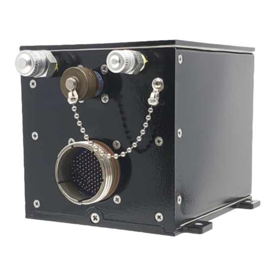
Page 6: Overview
Document Author: Project Manager 3 Overview The AHR150A family of ADAHRS are all composed of 2 boxes: an ISU (AHR150A-1) containing inertial and air data sensors, power conditioning, processors and ARINC 429 communication ports, and an MSU (AHR150A-2) containing a 3 axis magnetometer and processor for magnetic field measurements. -
Page 7: Mechanical Installation
The AHR150A-1 is intended to be installed in the nose or avionics bay of the aircraft. If the AHR150A-1 is installed in an area where the vibration profile exceeds the qualification profiles, the unit may not function as intended. -
Page 8: Orientation
Revision: C Release Date: 18DEC2014 Document Author: Project Manager Figure 2: AHR150A-1 ISU Mounting Holes and Alignment Patterns 4.1.1 Orientation The ISU can be installed in a variety of orientations. The connector side (CS) and the feet side (FS) can be oriented along the positive and negative directions of the principal axes of the aircraft as defined by Table 1 and Figure 3. -
Page 9: Figure 3: Isu Orientation Definitions (Shown In +X, +Z)
Installation Manual Document Number: ISM-AHR150A-1 Revision: C Release Date: 18DEC2014 Document Author: Project Manager AHR150A-1 Connector Side (CS) +X (Direction of Feet Side (FS) Figure 3: ISU Orientation Definitions (Shown in +X, +Z) For the installation shown in Figure 4, the orientation is 0000 (Connector Aft(-X), Feet Down(+Z)). -
Page 10: Pitot Port Connection
Document Author: Project Manager 4.1.2 Pitot Port Connection The AHR150A-1 has a single Pitot Pressure port consisting of an AN4 Male connector. The thread used for the AN4 connector is MS33656-4 (7/16-20 male thread for 1/4” tubing). During a pressurization test on the ground, the hull pressure is raised to 75 K Pa (-15,000 feet). -
Page 11: Electrical Installation
5.1 ISU Wiring 5.1.1 Electrical Connections The electrical connections to the AHR150A-1 are on one circular Mil-C-38999 23-35 filtered connector for normal operations. This connector is designated P2 and the pin outs for the P2 connector can be found in ISU Pin out Definitions for P2 Connector . -
Page 12: Isu Pin Out Definitions For P2 Connector
Installation Manual Document Number: ISM-AHR150A-1 Revision: C Release Date: 18DEC2014 Document Author: Project Manager 5.1.2 ISU Pin out Definitions for P2 Connector Signal Signal ARINC 429 Port 1 Transmit, A1, Hi Reserved Speed ARINC 429 Port 2 Transmit, A2, Hi... - Page 13 Case Common Signal Return Isolated from MSU Power Negative (AHR150A-2) Case Common Signal Return Isolated from AHR150A-1 Discrete Fault Line Case MSU RS422 Port Transmit A, Positive AOA Sensor, Negative MSU RS422 Port Transmit B, Negative Outside Air Temperature, Negative...
-
Page 14: Isu Power Connections
Table 2: ISU Pin out Definitions for P2 Connector 5.1.3 ISU Power Connections The power source for the AHR150A-1 is an isolated DC power supply using redundant input power lines as specified in Table 3. Failure of either power line can be detected and reported. -
Page 15: Wire Sizing Recommendations
Installation Manual Document Number: ISM-AHR150A-1 Revision: C Release Date: 18DEC2014 Document Author: Project Manager 5.1.4 Wire Sizing Recommendations The following are the recommended gauge wire sizes for the P2 mating connector. Signal Name Wire Type Power+, Power- 22 AWG twisted shielded pair... -
Page 16: Unit Id
The Orientation bits 0, 1, 2 and 3 give sixteen possible orientations (only 8 are currently available; see Table 1) for the AHR150A-1, when mounted on the aircraft. Figure 3 depicts the relationship between the AHR150A-1 and the aircraft principal axes. -
Page 17: Source Error And Lever Arm Corrections
Installation Manual Document Number: ISM-AHR150A-1 Revision: C Release Date: 18DEC2014 Document Author: Project Manager For example, to indicate an orientation of 0111, the Orientation Bit 2, Orientation Bit 1 and Orientation Bit 0 pins must be connected to RTN and the Orientation Bit 3 pin must be left open. -
Page 18: Cw Control
5.4.4 AHR150A-2 MSU Failure When a magnetometer (MSU) failure is detected, the AHR150A-1 automatically switches to DG mode, irrespective of the DG mode switch setting. The magnetometer failure is relayed in the output ARINC label 271 discrete bit 'MSU Fail', and the DG mode is indicated in the discrete label 270. -
Page 19: Discrete Output
The 11 transponder lines will then be active and can be connected to the transponder inputs. Pull up resistors are required but are usually part of the transponder. Should your installation appear to need the pull up resistors, contact Archangel. Page 19 of 26... -
Page 20: Notes
Installation Manual Document Number: ISM-AHR150A-1 Revision: C Release Date: 18DEC2014 Document Author: Project Manager 6 Notes 6.1 Alphabetical Listing of Acronyms and Abbreviations Acronym Meaning ARINC Aeronautical Radio Incorporated Archangel Systems Inc. Counter Clockwise Connector Side Clockwise Discrete Fault Output... -
Page 21: Application Note On Multiple Unit Installations
Installations of multiple Inertial Sensing Systems (ISS) in the same airframe present unique problems such as data agreement, co-alignment and operating environment. This is true of any ISS including the AHR150A-1 Air Data Attitude Heading Reference System Inertial Sensing Unit (ISU). To investigate such issues, Archangel Systems’ engineers performed extreme tests on the AHR150A-1 system. -
Page 22: Figure 9: Test Setup
Figure 9: Test Setup The output data from the two units (SN0171 and SN0172) were recorded using an ARINC bus tool. All work was conducted at Archangel Systems, Inc. Page 22 of 26... -
Page 23: Results
Installation Manual Document Number: ISM-AHR150A-1 Revision: C Release Date: 18DEC2014 Document Author: Project Manager 7.1.3 Results The roll and pitch angles are seen in Figure 10 and Figure 11, respectively. Figure 10: Inertial Roll Angle Results Note that neither unit diverged during the entire test from the ±60° Inertial Roll angles. -
Page 24: Figure 11: Inertial Pitch Angle Results
Installation Manual Document Number: ISM-AHR150A-1 Revision: C Release Date: 18DEC2014 Document Author: Project Manager Figure 11: Inertial Pitch Angle Results Note that neither unit diverged during the entire test from the ±60° Inertial Pitch angles. Additionally, it should be noted that the two units agree very closely with each other throughout the test. -
Page 25: Discussion
Systems for calibration and testing. The essence of those procedures is the use of fudicial pins in the mounting plates that mate with holes in the base plate of the AHR150A-1 and AHR75 in order to achieve tight alignment agreement. -
Page 26: Conclusions
Installation Manual Document Number: ISM-AHR150A-1 Revision: C Release Date: 18DEC2014 Document Author: Project Manager Figure 12 shows a representative plate where two AHR150A or AHR75 are installed ‘back to back’. The AFT ISU would be strapped in orientation ‘0’ with the connector facing to the rear of the aircraft.
Need help?
Do you have a question about the AHR150A-1 and is the answer not in the manual?
Questions and answers