Table of Contents
Advertisement
Advertisement
Table of Contents

Related Manuals for MicroPort SpiderView


Summary of Contents for MicroPort SpiderView
- Page 1 SpiderView Digital Holter Recorder U S E R M A N U A L...
-
Page 3: Table Of Contents
INTRODUCTION ......................5 1.1. Use in the United States..................... 5 SPIDERVIEW PRESENTATION................6 2.1. Intended use....................... 6 2.2. Specific features of SpiderView.................. 6 2.3. Packaging........................6 USER PROFILE ......................7 3.1. Training ........................7 PRECAUTIONS FOR USE AND MAINTENANCE ............ 8 4.1. - Page 4 Guidance and manufacturer's declaration: cable length .......... 35 15.3. Guidance and manufacturer's declaration: electromagnetic emissions ....36 15.4. Guidance and manufacturer's declaration: electromagnetic Immunity..... 36 15.5. SpiderView and mobiles (recommendations)............39 15.6. CANADA ........................39 15.7. UNITED STATES ..................... 39 SpiderView – UA10709B...
-
Page 5: Introduction
This icon alerts you to a hazard that may result in equipment damage or personal injury. Carefully read the instructions provided with this icon. 1.1. USE IN THE UNITED STATES [CAUTION: Federal law restricts the sale of this device by or on the order of a physi- cian.] SpiderView – UA10709B... -
Page 6: Spiderview Presentation
MicroSD cards. SpiderView is not compatible with the ELATEC and SyneView analysis software systems. SpiderView recordings longer than 24h and with more than 3 channels must be read with SyneScope. SpiderView 24h recordings, 2/3 channels can be read with SyneScope, SyneTec, EasyScope, SyneView2 and SyneCom. -
Page 7: User Profile
Any person who has followed the training required by the local regulatory authority. Training completion and effectiveness are under his/her medical supervisor’s responsibility. NOTE: Any serious incident that has occurred in relation to the device must be reported to MicroPort CRM S.r.l. and your competent authority. SpiderView – UA10709B... -
Page 8: Precautions For Use And Maintenance
TRANSPORTATION SpiderView is packaged for delivery as outlined in the packaging chapter. If you want to repack and carry or deliver the SpiderView after its first usage, we recommend putting all the parts back into their initial positions. Please take care putting the flash card case into the appropriate place. -
Page 9: Electromagnetic Compatibility
WARNING: SpiderView does not start if a MicroPort flash card is not inserted. SpiderView is only guaranteed to work properly if flash cards supplied by MicroPort are used. Furthermore, flash cards designed for use in MicroPort recorders should not be used for other applications. -
Page 10: Warranty
5. WARRANTY WARRANTY SpiderView and flash cards are guaranteed for parts and work for two years from the date of delivery. After-sales service is available after the warranty has expired. WARNING: The warranty is only valid under the condition that no attempts have been made to open or repair the device. -
Page 11: General Description
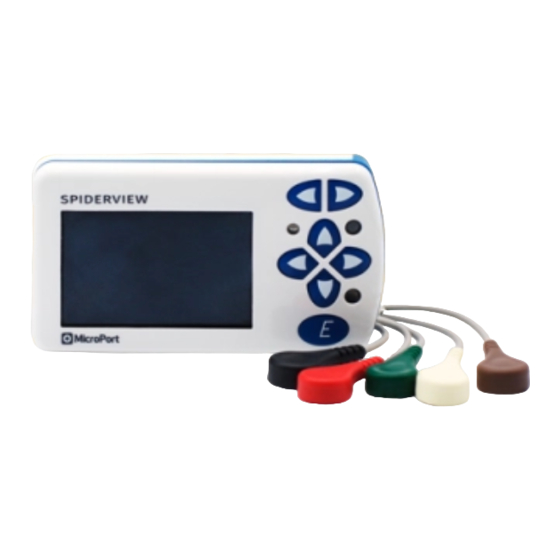
6. GENERAL DESCRIPTION GENERAL DESCRIPTION 6.1. SPIDERVIEW COMPONENTS (2) Screen buttons (3) Cursor buttons (4) Event button (5) LCD display (6) Operating light (LED) (1) On/off button (7) Patient cable connector SpiderView – UA10709B... -
Page 12: Description Of Symbols On The Case And Packaging
The following symbols are displayed on the SpiderView case and packaging: Device classified as BF (IEC 60601-1). Refer to the SpiderView user manual before handling the part of the device with this symbol. Consult instructions for use available on CD-ROM Consult the documentation and manual enclosed in the packaging. -
Page 13: Opening The Battery Cover
The insertion (first A then B) and extraction (first C then D) of the patient cable should be done as indicated in the picture below. NOTE: When SpiderView is not in use, it can be stored without disconnecting the patient’s cable from the plug. -
Page 14: Use Of Batteries
If the voltage is not sufficient for another 24h recording, a warning message will appear after switching on the device. NOTE: If SpiderView is switched on when the battery is low, the duration of the recording will be one day only (24h), regardless of the programmed time. -
Page 15: Positioning The Electrodes
8. POSITIONING THE ELECTRODES POSITIONING THE ELECTRODES WARNING: Connect the patient to the SpiderView only when the back of the SpiderView is in place. Electrodes supplied with SpiderView have been designed to withstand long-term ambulatory recording while ensuring patient comfort. Nevertheless, other ECG electrodes may be used. -
Page 16: Two Channel Recording (5 Electrodes)
The ground electrode is placed on a rib on the right side of the chest. Positioning of electrodes for CMV5, CMAVF2 is shown in the figure below: SpiderView – UA10709B... -
Page 17: Three Channel Recording (7 Electrodes)
LAD artery and circumflex artery. The blue electrode lies posteriorly and paravertebrally facing V2. The orange electrode is placed in V2. The ground electrode is placed on a rib on the right side of the chest. SpiderView – UA10709B... -
Page 18: Xyz Channel Recording (7 Electrodes)
8.5. TWELVE-LEAD RECORDING* (10 ELECTRODES) 8.5.1. ELECTRODES Yellow Left Anterior acromium Right Anterior acromium Green Left Interior iliac crest Black Right Interior iliac crest Purple V1 position SpiderView – UA10709B... - Page 19 ― Leads V1 to V6 (precordial leads) V4 V5 The central terminal of Wilson is automatically calculated by SpiderView. Because of ambulatory conditions we recommend placing electrodes on the roots of the limbs (Mason-Likkar configuration), often used in exercise testing.
-
Page 20: Using The Programming Buttons
Moving to the left allows access to the device’s parameters (date, time, voltage, contrast …). Moving to the right allows you to set the recording’s parameters and to begin the recording. The following chapters will explain the details about the SpiderView screens. 9.2. STARTING THE DEVICE 9.2.1. - Page 21 WARNING: SpiderView is only guaranteed to work properly if flash cards supplied by MicroPort are used. If you do not use a MicroPort card, the following message will appear: “Warning: Unknown card provider”. Furthermore, a flash card designed for use in MicroPort recorders should not be used for other applications;...
-
Page 22: 10. Starting The Holter Recording
This must be done on the ECG screen: move the cursor to the field “No PM” and modify it using the buttons The device records single chamber or dual chamber pacemakers with two different sensitivities: Unipolar (less sensitive) or Bipolar (more sensitive). SpiderView – UA10709B... - Page 23 You may also insert a patient ID number that will be downloaded together with patient’s name. 10.1.5. Select the recording mode SpiderView can work in different recording modes using different resolutions: SpiderView – UA10709B...
- Page 24 WARNING: Please check that the display of the recorder is switched off and that the LED (6) is blinking before putting the recorder back into the pouch. This guarantees that the initialization phase has finished and that the device has started to record correctly. SpiderView – UA10709B...
- Page 25 Holter recording. Please refer to the table in this manual to check which combinations of modes and duration you can select according to the size of your card. SpiderView – UA10709B...
- Page 26 The battery capacity must be high enough to support the programmed duration and mode. WARNING: Only flash cards provided by MicroPort are fully compatible with SpiderView. Other flash cards can cause recording problems.
- Page 27 4 d + HR No Comp 3 d + HR High resolution only – 4095 min (68h15min) – 2100 min (35h) HR: 20 minutes of recording in “high resolution” mode * Devices available with SyneScope Holter software. SpiderView – UA10709B...
-
Page 28: 11. Device Parameters
Press the “E” button to know the correspondence between the impedance bar and the positioning of the electrode on the patient. An image will show how to position the electrodes on the patient’s thorax. SpiderView – UA10709B... -
Page 29: Time And Date Screen
NOTE: Time and Date are stored on the device and kept updated by the internal rechargeable battery for about a week. After switching on the recorder, if the SpiderView fails to retrieve the language, time or date from its memory, it will automatically display the setting screen for these parameters (language, date then time) so that you can re-enter this data. -
Page 30: Special Functioning Modes And Error Messages
“write” position. Unreadable card - Use Displayed when the flash card format is not one used by SpiderView. another card If an error of any type occurs during the functioning of the device, an error code is generated by the device and stored on the internal memory. - Page 31 Overrun on write-FIFO 0700 0125 Error while creating daily files 0701 Overrun on spike buffer 0126 Error while opening daily files 0127 Overrun on follow-up buffer 0128 Overrun on marker buffer 0129 Overrun on ECG CRC buffer SpiderView – UA10709B...
-
Page 32: 13. Technical Specifications
13. TECHNICAL SPECIFICATIONS 13. TECHNICAL SPECIFICATIONS 13.1. TYPE SpiderView digital Holter ECG and high resolution ECG recorder. This device is a AECG device type 1. 13.2. NUMBER OF LEADS Depending on the cable used, the device records the following leads: ―... -
Page 33: Radio Equipment Emission
Mb on your computer’s hard drive. 13.6. RADIO EQUIPMENT EMISSION Radio Equipment Transmitter Bands / Receiver Frequency Bands Maximal Power SpiderView [2400 ; 2483.5] MHz ; [2400 ; 2483.5] MHz Bluetooth® Low Energy ≤ 10 mW (0 dB) SpiderView – UA10709B... -
Page 34: 14. Accessories
Pack of 30 hypoallergenic ECG ✓ electrodes RE150 Pack of 4 AA Alkaline batteries ✓ RE154 Pack of 4 AA Lithium batteries ✓ LA459 1 GB MEMORY CARD ✓ LA464 256 MB SD card for SpiderView and ✓ SpiderFlash recorders SpiderView – UA10709B... -
Page 35: 15. Appendix
The use of accessories other than those specified or sold by MicroPort CRM as replacement parts, may result in an increase in the emission or a decrease in the immunity of the medical device and may cause an inappropriate operation. -
Page 36: Guidance And Manufacturer's Declaration: Electromagnetic Emissions
GUIDANCE AND MANUFACTURER'S DECLARATION: ELECTROMAGNETIC IMMUNITY SpiderView is intended for use in the electromagnetic environment specified below. The customer or the user of the SpiderView should ensure that it is used in such an environment. Immunity test IEC 60601 Compliance... - Page 37 WARNING: Portable RF communication devices (including peripherals such as antenna cables and external antennae) should not be used closer than 30 cm (12 inches) to any part of the SpiderView, including the specified cables. Otherwise, the performance of this device may be impaired.
- Page 38 Interference may occur in the vicinity of equipment marked with the following symbol: NOTE: These guidelines may not apply in all situations. Electromagnetic propagation is affected by absorption and reflection from structures, objects and people. SpiderView – UA10709B...
-
Page 39: Spiderview And Mobiles (Recommendations)
15. APPENDIX 15.5. SPIDERVIEW AND MOBILES (RECOMMENDATIONS) The SpiderView is intended for use in an electromagnetic environment in which radiated RF disturbances are controlled. Portable RF communication devices (including peripherals such as antenna cables and external antennae) should not be used closer than 30 cm (12 inches) to any part of SpiderView, including the specified cables. - Page 40 CAUTION: This equipment may not be modified, altered, or changed in any way without signed written permission from MicroPort CRM. Unauthorized modification may void the equipment authorization from the FCC and will void the MicroPort CRM warranty. This equipment complies with FCC radiation exposure limits set forth for an uncontrolled environment and meets the FCC radio frequency (RF) Exposure Guidelines.
- Page 42 MicroPort CRM S.r.l. Via Crescentino S.N. 13040 Saluggia (VC) Italy Tel: +39 0161 487095 www.microport.com 2021-11 UA10709B...
Need help?
Do you have a question about the SpiderView and is the answer not in the manual?
Questions and answers
what e21 means?