Advertisement
DEM680E Series Delayed Egress
Magnalock
Installation & Operating Instructions
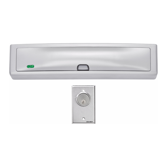
Product Components
A Magnalock & Mounting Bracket
B Strike Housing
C Strike Plate Assembly
D Wall Mounted Key Switch
Installation Hardware Pack Contents
I #14 X 3" Type A Phillips
Pan Head Screw (4)
J Threadlocker Packet
K WOOD DOORS: #6 X
1/2" Phillips Flat Head
Type A Steel Screw (6)
L METAL DOORS: 6-32 X
3/8" Phillips Flat Head
Type F Steel Screw (6)
NOTE: Hardware is provided for various installations.
There will be leftover parts depending on the type of installation.
Specifications
Dimensions
•
Height: 2.50" [64 mm]
•
Depth: 2.56" [65 mm]
•
Length: 11.50" [292 mm]
Certifications
•
UL 10C Fire Rated, 1 Hour
•
CAN/ULC-S104 Fire Door Conformant
•
UL 294
•
UL Tested Ratings: Endurance:
100,000 cycles
•
ANSI/BHMA A156.23, Grade
2; E18501 Compliant
•
California State Fire Marshal Listed
•
NFPA 101
IMPORTANT: UL 294 compliance requires that the locking device be powered by a UL
294 (ALVY) or UL 603 (APHV) listed power supply and shall be installed in accordance
with the following UL and National Standards: NFPA 70 – National Electrical Code.
®
with EcoMag
E Settings Labels
F Sex Bolt & Tapered Washer
G Template Pins
H NFPA Door Label
M #12 X 1-1/2" Type A Phillips
Pan Head Screw (4)
N Rivet Nut Install Tool
O 1/4-20 X 1" Phillips Pan
Head Screw (2)
P 1/4-20 Rivet Nut (2)
Q 3/16" Hex Key
Electrical
•
Magnalock Minimum Current Draw
(±10%)
95 mA at 12 VDC
65 mA at 24 VDC
•
Magnalock Maximum Current Draw
(±10%)
575 mA at 12 VDC
315 mA at 24 VDC
Static Holding Force
•
1,200 lbs [544kg]
Operating Temperature
•
32˚ to 120˚F [0˚ to 49˚C]
•
Indoor use only
Technology
™
IMPORTANT This Magnalock requires calibration upon installation.
Diagram 1 Product Components
B
C
D
H
I
M
A
E
G
F
J
K
L
O
Q
N
P
1 of 12
Advertisement
Table of Contents

Related Manuals for Securitron ASSA ABLOY Magnalock DEM680E Series


Summary of Contents for Securitron ASSA ABLOY Magnalock DEM680E Series
- Page 1 DEM680E Series Delayed Egress Magnalock ® with EcoMag Technology ™ Installation & Operating Instructions Product Components IMPORTANT This Magnalock requires calibration upon installation. Diagram 1 Product Components A Magnalock & Mounting Bracket E Settings Labels B Strike Housing F Sex Bolt & Tapered Washer C Strike Plate Assembly G Template Pins D Wall Mounted Key Switch...
- Page 2 NOTE 1: Blind nuts provide a highly secure and tamper- resistant system for mounting and are provided for this unit. NOTE 2: A blind nut installation tool (Securitron BPT- 2, Blind Nut Placement Tool, or similar) can be used Preparing the Magnalock Diagram 3a Removing the cover instead of using a box end wrench and hex wrench.
- Page 3 Installing the strike Mounting the Diagram 16 Mounting the Diagram 17 Marking the back Diagram 11 Marking the Magnalock to the bracket edge of the mounting bracket strike housing mounting hole Diagram 12 Drilling the sex on the door Magnalock and aligning locations from the inside bolt hole from the outside to the strike plate...
- Page 4 Diagram 29 Jumper Locations Table 1 Jumper Settings MAGNALOCK ELECTRICAL INSTALLATION H2 (BOND) Jumpers Position Selection Function/Description Factory Default H3 (DPS) JP3 (EXT INIT) H2 (BOND) Normally Normally closed circuit – opens closed (NC) when BOND registers secure. Normally closed Pulling the wiring Diagram 24 Location of J1 and J4 terminals Normally...
-
Page 5: Initial Calibration
Delayed Egress Initial calibration Diagram 34 Calibration button status LEDs NOTE 1: If calibration does not proceed according to the instructions Diagram 31 LED location below, please see the troubleshooting section at the end of the manual. The two LEDs shown display the NOTE 2: Initial calibration can be performed with a 12-V battery for Calibration Button following Delayed Egress states. -
Page 6: Troubleshooting Guide
Troubleshooting Guide MAGNALOCK OPERATIONAL TESTS TROUBLE INDICATOR POSSIBLE CAUSES POSSIBLE SOLUTIONS Test 1 – Verifying Diagram 36 Indicator light displays • Two bond sensor failures* • Ensure bond sensor connectors are properly seated Solid RED • Supply voltage < 8.5 VDC •... -
Page 7: Warranty
SET SW 10 to OFF. The unit should auto-calibrate. If the unit fails to calibrate see Troubleshooting Guide, or contact technical support. Warranty For information on warranty coverage and replacement options, please visit securitron.com/warranty Printed in the U.S.A. techsupport.securitron@assaabloy.com Patent pending and/or patent www.assaabloydss.com/patents securitron.com | 800 626 7590...
Need help?
Do you have a question about the ASSA ABLOY Magnalock DEM680E Series and is the answer not in the manual?
Questions and answers