Sign In
Upload
Download
Table of Contents
Contents
Add to my manuals
Delete from my manuals
Share
URL of this page:
HTML Link:
Bookmark this page
Add
Manual will be automatically added to "My Manuals"
Print this page
×
Bookmark added
×
Added to my manuals
Manuals
Brands
Securitron Manuals
Locks
Magnalock M32
Installation and operating instructions manual
Securitron Magnalock M32 Installation And Operating Instructions Manual
Hide thumbs
1
Table Of Contents
2
3
4
5
6
7
8
9
10
11
12
13
14
15
16
17
18
19
20
page
of
20
Go
/
20
Contents
Table of Contents
Troubleshooting
Bookmarks
Table of Contents
Table of Contents
Introduction
Specifications
General
Perform a Product Inventory
Have the Recommended Tools
Perform a Pre-Installation Survey
Installing a Magnalock
Attach the Template and Mark the Drill Holes
Drill the Holes for the Lock Body and Strike Plate
Install the Blind Nuts
Install the Strike Plate
Install the Magnalock
Wire Double Door Status
Wire Double Door Status-DPS
Wire for Emergency Release
Maintaining a Magnalock
Perform an Inspection
Clean the Magnalock
Troubleshooting a Magnalock
Determining Wire Gauge
Warranty
Advertisement
Quick Links
1
Specifications
2
Installing a Magnalock
3
Attach the Template and Mark the Drill Holes
4
Install the Strike Plate
5
Install the Magnalock
6
Wire Double Door Status
7
Wire for Emergency Release
8
Troubleshooting a Magnalock
Download this manual
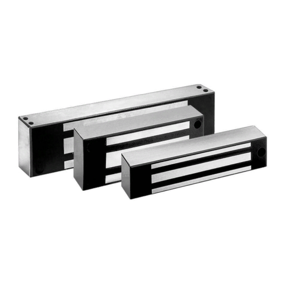
Models M32, M62, and M82B
Installation and Operating Instructions
1
10027 S. 51st St. Ste 102
Phoenix, AZ 85044
Tel: 1-800-624-5625
Mon-Fri: 6:00am - 4:00pm PDT
Magnalock
securitron.com
techsupport@securitron.com
®
500-10420, Rev G
Table of
Contents
Previous
Page
Next
Page
1
2
3
4
5
Advertisement
Table of Contents
Need help?
Do you have a question about the Magnalock M32 and is the answer not in the manual?
Ask a question
Questions and answers
Related Manuals for Securitron Magnalock M32
Locks Securitron Magnalock M62 Installation And Operating Instructions Manual
(20 pages)
Locks Securitron ASSA ABLOY Magnalock DEM680E Series Installation & Operating Instructions Manual
Delayed egress with ecomag technology (7 pages)
Locks Securitron Vista V2M1200 Installation Instructions Manual
(12 pages)
Locks Securitron Vista VM300 Series Installation Instructions
Magnetic lock (2 pages)
This manual is also suitable for:
Magnalock m62
Magnalock m82b
Table of Contents
Print
Rename the bookmark
Delete bookmark?
Delete from my manuals?
Login
Sign In
OR
Sign in with Facebook
Sign in with Google
Upload manual
Upload from disk
Upload from URL


Need help?
Do you have a question about the Magnalock M32 and is the answer not in the manual?
Questions and answers