Advertisement
Quick Links
Installation Instructions
Door Loop
(Optional)
The door loop protects the wiring
from damage at the door hinge.
Attention! Please ensure that the
template is the correct way up
ø5.0
Alignment CL
Align the center line (CL) of the lock
ø5.0
body template with the CL of the door
Cut out mortise holes for the lock
leaf. Ensure the CL of the strike plate
body and strike plate and drill
template matches the lock body CL as
holes according to the templates.
closely as possible.
Connect power cable to the lock
and test before screwing to the
door leaf.
Copyright © All Rights Reserved. P-MU- ML-210 Ver. C Publish: 2010.12.02
Unit:mm
ø5.0
ø5.0
ø5.0
ø5.0
Tighten the fixing lugs with
screws.
Affix the strike plate.
4 - 4
ML-210
ML-210-SW
Specifications
Operating Voltage» ML-210: 12 or 24VDC
ML-210-SW: 12~24VDC/AC
Voltage Tolerance» ±10%
Current Draw» ML-210: 280mA/12VDC; 140mA/24VDC
ML-210-SW: 210mA/12VDC; 150mA/24VDC
Version Changeable» Fail-safe or Fail-secure
Operating Temperature» -10~45°C
Humidity» 0~95% non-condensing
Lock bolt sensor switch output» SPDT rated 3A/125VAC
Solenoid testing» Tested to 1,000,000 cycles
Net Weight» ML-210: 540g / ML-210-SW: 555g
Just applicable to vertical installation
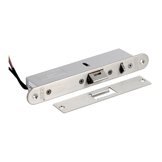
Packing Contents
Fixing Lug
Allen wrench (1.6mm)
Nib
Lock bolt
Strike Plate
Version Changeable:
Take out the Screw 1 , release the screw 2 , move the
position and then tighten both screws.
"Fail-Safe"
"Fail-Secure"
(Power to Lock)
(Power to Open)
Caution:
Do not completely remove screw 2 (as marked in the figure)
as the interior solenoid might fall off.
Copyright © All Rights Reserved. P-MU- ML-210 Ver. C Publish: 2010.12.02
Electromechanical Lock
Installation Instruction
Double Swing Doors
Double swing door
Outswing
Template
ø5.0
ø5.0
4-R2
25
30
22
Alignment CL
206
150
38
33
Butt Splice (IDC) Connector
Using crimper or pliers and pressing the header of
connector down to even position.
Inswing
Unit:mm
210
253
4 - 1
Advertisement

Related Manuals for Gianni Industries ML-210


Summary of Contents for Gianni Industries ML-210
- Page 1 Connect power cable to the lock Affix the strike plate. and test before screwing to the door leaf. Copyright © All Rights Reserved. P-MU- ML-210 Ver. C Publish: 2010.12.02 Unit:mm Specifications ø5.0 Operating Voltage» ML-210: 12 or 24VDC Voltage Tolerance»...
- Page 2 24VDC Power supply N.O. contact Black Varistor (Power input is polarity free) “Fail-Secure” (Power to Open) Copyright © All Rights Reserved. P-MU-ML-210 Ver. C Publish: 2010.12.02 Wiring Diagram ML-210-SW Voltage Input: 12~24VDC/AC For the 12~24VDC/AC operation only Yellow Green Blue Access Control Device N.O.
Need help?
Do you have a question about the ML-210 and is the answer not in the manual?
Questions and answers