
Subscribe to Our Youtube Channel
Related Manuals for Kobelt 7178 Series


Summary of Contents for Kobelt 7178 Series
- Page 1 7178 Panoramic Rudder Angle Indicator Owner’s Installation, Operation & Maintenance Manual...
- Page 2 NOTES RECORD DATA BEFORE INSTALLATION FOR FUTURE REFERENCE Model #: Serial #: Date of Purchase: Date of Installation: rev A MNL-7178.docx 2 of 19...
-
Page 3: Table Of Contents
ABLE OF ONTENTS Introduction ......................4 Contact ........................4 Safety .......................... 4 Product Description ....................6 Technical Data ......................6 Installation ......................8 Mechanical ......................... 8 Electrical ........................8 Commissioning ....................10 Electrical Check......................10 Calibration and Adjustment ..................10 Functional Test ...................... -
Page 4: Introduction
Kobelt reserves the right, without notice, to change the design, or construction, of any products and to discontinue or limit distribution of any products. Kobelt also reserves the right to change, or update, without notice, any technical information contained within this document. - Page 5 • Do not carry out any modifications to the product. • Only use authentic Kobelt spare parts. • Observe all local regulations, directives and laws during the installation of this product. • All installation, commissioning, and maintenance work must only be conducted by qualified personnel.
-
Page 6: Product Description
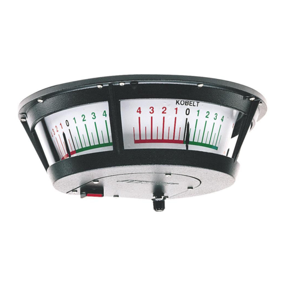
The 7178 Analog Indicator displays rudder angle position, on three scales to provide 230 degrees of viewing angle within the Vessel’s bridge. The indicator is driven by a position transducer such as the Kobelt 7163, 7168, or 7174 Rudder Feedback Units (RFU). ECHNICAL... - Page 7 TERMINALS 22-16 AWG, screw clamp EMC EMMISIONS per IEC 60945 EMC IMMUNITY per IEC 60945 COMPASS SAFE DISTANCE 2 in [5 cm] ENVIRONMENTAL CATEGORY ENV2 / class A / protected INGRESS PROTECTION IP20 OPERATING TEMPERATURE -4°F … 131°F [-20°C … 55°C] ENVIRONMENTAL CONDITIONS per DNV No.
-
Page 8: Installation
Power connections are made at connector P4 whereas the potentiometer input from the RFU is made at connector P3. Rudder Feedback Unit signals shown in the following figures are provided by standard Kobelt RFUs. Please review the Kobelt website for all RFU options available. - Page 9 Figure 2: Electrical Connections Disconnect Power: Turn off power at distribution panel before beginning installation to protect installer from electrical hazards. rev A MNL-7178.docx 9 of 19...
-
Page 10: Commissioning
OMMISSIONING LECTRICAL HECK Ensure that the unit is properly installed and secured before powering on the 7178. • Confirm that all electrical connections to the 7178 have been made. • Confirm that a breaker has been installed correctly and is turned ON. ALIBRATION AND DJUSTMENT The indicator may need to be adjusted to correct the overall range of the meter to align with... -
Page 11: Functional Test
4.2.2 “SPAN” Trimpot: Adjust Range Size The span adjust trimpot adjusts the range of the meter. The range reported by the RFU will vary depending on mechanical linkages. This trimpot can be used to calibrate the hard-over angles. Reference Figure 1: Rudder Angle Indicator Overview for the span trimpot location. -
Page 12: Maintenance
NITS Depending on the date of purchase, a retrofit motor diver chip may be required if replacing the motor. When ordering a new motor for Kobelt panoramic RAIs with serial numbers #396 or lower the following parts must be ordered: rev A MNL-7178.docx... - Page 13 Figure 3: Motor driver Chip It is recommended that any required service work on a Kobelt unit be performed by a factory authorized service representative. Please contact the nearest Kobelt authorized distributor for assistance.
-
Page 14: Troubleshooting
If you encounter problems with the operation of your product, please refer to the trouble- shooting suggestions before contacting Kobelt for assistance. If the steps below do not resolve your issue, please reach out either Kobelt directly or our Dealers in your area. Table 4: Common Solutions... -
Page 15: Warranty
If any part is found to be defective, Kobelt will replace said part FOB the Kobelt factory provided that any such defective part is returned by the Buyer with freight and applicable forwarding charges prepaid by the Buyer. -
Page 16: Appendix A: Installation Dimensions
A: I PPENDIX NSTALLATION IMENSIONS Figure 4: Mechanical Dimensions of 7178 rev A MNL-7178.docx 16 of 19... -
Page 17: Appendix B: Parts List
B: P PPENDIX ARTS rev A MNL-7178.docx 17 of 19... - Page 18 ITEM QTY PART NUMBER DESCRIPTION 7178-K24V-SUB 7178 MAIN SUBASSEMBLY 7178-0001-B HOUSING, 7178, TEXTURED BLACK 7178-0002 BACK PLATE, 7178 7178-0003 INSPECTION COVER, BACK, 7178 7178-0004 SUPPORT HUB 7178-0005 POINTER HOLDER 7178-0006-B INSPECTION COVER, FRONT, 7178, TEXTURED BLACK 7178-0008 BRACKET, LAMP & TERMINAL BLOCK, 7178 7178-0009-IN LENS, INNER, 7178 7178-0009-OUT...
- Page 19 Kobelt Manufacturing Co. Ltd. 8238 129th Street Surrey, British Columbia, Canada, V3W 0A6 Sales Tel: +1-604-572-3935 Fax: +1-604-590-8313 Email: sales@kobelt.com Website: www.kobelt.com Made in Canada / Printed in Canada...
Need help?
Do you have a question about the 7178 Series and is the answer not in the manual?
Questions and answers