Table of Contents
Advertisement
Quick Links
Advertisement
Table of Contents

Related Manuals for Apogee NAVIK 100

Summary of Contents for Apogee NAVIK 100
- Page 1 NAVIK 100 GNSS Receiver User Guide Version – 1.0 November 2021...
- Page 2 Email: sales@apogeegnss.com No: 7624002254 Copyright Notice This is the V1.0 (Oct, 2021) revision of the NAVIK 100 GNSS Receiver User Guide. It cannot be copied or translated into any language without the written permission of Apogee GNSS Pvt Ltd. Technical Assistance If you have any question and can't find the answer in this manual, please contact your local dealer from which you purchased the NAVIK 100 GNSS Receiver.
- Page 3 CAUTION- A Caution alerts you to a possible risk of damage to the equipment and/or data loss. Warranty Notice Apogee GNSS Pvt Ltd does not warranty devices damage because of force majeure (lighting, high voltage or collision). Apogee GNSS Pvt Ltd does not warranty the disassembled devices.
-
Page 4: Table Of Contents
CONTENTS 1 Introduction.........................6 1.1 About the Receiver..................6 1.2 Receiver Features..................6 1.3 NAVIK 100 Receiver Parts List................6 1.3.1 Basic Supply Kit................7 2 Setting Up the Receiver....................8 2.1 Environmental Requirements................8 2.2 Front Panel.....................8 2.3 Lower Housing....................9 2.4 Power Supply....................9 2.4.1 Internal Battery................9 2.4.2 External Power Supply..............10... - Page 5 7.3 NMEA 0183 Output....................29...
-
Page 6: Introduction
1 Introduction The NAVIK 100 GNSS Receiver User Guide is aimed to help you get familiar with the NAVIK 100 Receiver and start your project effectively. We highly recommend you to read this manual before surveying. 1.1 About the Receiver NAVIK 100 GNSS Receiver can be applied in RTK mode with all GNSS constellations. - Page 7 1. NAVIK 100 GNSS Receiver 2. RF Antenna 3. D-45 Data Collector 4. Lemo to DB9 Cable 5. Adapter 6. Quick start guide 7. Survey Pole 8. Power Supply...
-
Page 8: Setting Up The Receiver
2 Setting up the receiver This chapter provides general information on environmental requirements, setup, power supply and connection of the NAVIK 100 receiver. 2.1 Environmental requirements To keep the receiver with a reliable performance, it is better to use the receiver in safe environmental conditions: ... -
Page 9: Lower Housing
The receiver is equipped with one rechargeable Lithium-ion battery, which can be removed for charging. The NAVIK 100 receiver adopts the hot swap battery design that provides you an effective survey workflow. Receiver is powered by high capacity 6800 mAh Li-ion battery. Its operating time depends on that it is working as a rover or as a base station with internal UHF Tx (transmit at 1 W adjustable). -
Page 10: External Power Supply
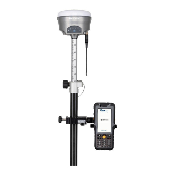
The receiver is connected to an external power supply through a lemo to RS232 cable, and make sure that the red alligator clip is connected to the positive of external power supply, black one to negative. Over-voltage function cannot protect your NAVIK 100 receiver if reverse connection. 2.5 Pole-mounted setup To mount the receiver on a range pole as the figure shown below: ... -
Page 11: General Operation
Install the controller into the bracket 3 General Operation This chapter introduces all controls for the general operation, including button functions and all LED behaviours on the front panel. 3.1 Button functions Power button: Press the power button for about 1 second to turn on the receiver; To turn off the receiver, long press the button for 3 seconds until all LEDs off. -
Page 12: Static Survey
Static GNSS surveys deliver the highest-accuracy positions available in a system, which occupies a point for longer periods of time than kinematic systems. Static systems include a range of survey styles from rapid static surveys to continuously operating stations, such as CORS sites. The equipment setup varies significantly, depending on how long the site will be operational, which could vary from 15 minutes to several years. -
Page 13: Static Data Download
GNSS receivers generally collect and store the raw GNSS data in a proprietary format, which may need to be translated into a different format for data processing or data sharing. RINEX (Receiver Independent Exchange Format) is the ubiquitously accepted data format for raw GNSS data. Reference site data is generally provided in RINEX. -
Page 14: Real Time Kinematic Survey (Rtk)
5 Real-Time Kinematic Survey (RTK) This chapter introduces how to conduct RTK Survey with Geo Master app, including software installation, start a new project, receiver connection and RTK working modes (Radio and GPRS). 5.1 Installation of GEO Master We can download the GEO Master app from the download center tab of the company section of the website name apogeegnss.com. - Page 15 2. Connection: Click Select to go into Bluetooth connection interface. 3. Work mode: Click select to go into Quick Setup interface to start your receiver as Base/Rover. If you start your receiver as Rover, then you can start work directly of Topo survey or stakeout.
-
Page 16: Start A New Project
If you start your receiver as Base, after Disconnect with Base, there will be a Prompt. YES: will guide you to start Rover in Wizard interface; NO: will exit Wizard. 5.3 Start a New Project Click Project, select Predefinedor User definedcoordinate system. Also, you can use the same Datum with an existing project. - Page 17 Predefined: You can select the coordinate system directly. GEO Master has coordinate systems of all countries in the list. User defined: If you cannot find the coordinate system you want in predefined, follow instructions below to add a datum. Enter Name—select an existing Ellipsoid—select a proper Projection and input the corresponding parameters.
-
Page 18: Bluetooth Connection
5.4 Bluetooth Connection To connect GEO Master with NAVIK 100, switch to Device interface, tap Connection to go into Bluetooth connection interface. -
Page 19: Internal Radio Mode
5.5 Internal Radio Mode NAVIK 100 GNSS receiver supports transmit & receive the correction data in internal radio mode. To conduct the RTK survey in internal radio mode, it requires: 1) A controller with software installed 2) An extension bar... -
Page 20: Start Base Station By Geo Master Survey App
External Antenna. And others no need change. NAVIK 100 GNSS Receiver External Antenna 5.5.1 Start Base Station by GEO Master Firstly, build Bluetooth connection between the NAVIK 100 receiver and your controller. Secondly, modify parameters including correction format, antenna type and communication protocols:... - Page 21 Choose Protocol and Frequency for Base receiver. Start mode: Fix position (Manual Base setup) means you have a known coordinate for Base, or get a point from GNSS.
-
Page 22: Start Rover Station By Geo Master Survey App
5.5.2 Start Rover Station by Geo Master Survey App Connect GEO Master with NAVIK 100 receiver via Bluetooth. Set same protocol and frequency with Base receiver. The current status on the bottom will change from Single to Fixed. -
Page 23: Internal Gprs Mode
Rover An NAVIK 100 receiver II. A Whip Antenna III. A controller with software installed IV. A range Pole with bracket 5.7 Internal GPRS Mode For Internal GPRS mode, NAVIK 100 receiver supports Internal GSM and Ntrip client mode. -
Page 24: Internal 4G
5.7.1 Internal GSM In Internal GSM mode, you need to set the data link as Internal GSM, Sever, IP Port. 6 Basic Survey Functions This section describes the basic survey functions of Geo Master, including point measurement, Topo survey, Auto survey, Area survey, Static, PPK, staking, site calibration, import and export measured points. -
Page 25: Auto Survey/Area Survey
6.2 Auto Survey For Auto survey, it supports automatic and continuous survey according to Time or Distance. -
Page 26: Stake Points/Lines
6.3 Stake points/lines Go into Stake point interface, click to choose a point and tap Stake. GEO Master provides a navigation map when staking points/lines. If you are close to the target point enough, it will alarm you based on the alarm range you set. Enter the point name and code based on your requirements. -
Page 27: Site Calibration/Grid Reset
6.5 Site calibration/Grid Reset Site calibration is commonly needed once in one project, and all the points will be collected based on calibrated datum system. 6.5.1 Site Calibration This is in the progressing state. 6.6 Area Calculation and COGO This is in the progressing state. 7 Data Export/Import With import/export functions, you can import and export any survey data, files and stake points/lines fluently. -
Page 28: Export
7.2 Export Tap Export to export survey points. File format: support *.csv, *.dxf, *.txt format The default export path is .../../.. - Page 29 7.3 NMEA 0183 Output With NMEA 0183function, you can quickly set to output NMEA data from lemo port or Bluetooth. In fact, this function is same as enter commands “log comXgpXXXontime X”. Choose NMEA Port -> Baud -> check commands you want to output -> click to ok start...
Need help?
Do you have a question about the NAVIK 100 and is the answer not in the manual?
Questions and answers