
Subscribe to Our Youtube Channel
Related Manuals for Smartgen HWP40-3


Summary of Contents for Smartgen HWP40-3
- Page 1 HWP40-3/HWP60-3 FORCED CIRCULATION HEATER USER MANUAL SMARTGEN (ZHENGZHOU) TECHNOLOGY CO., LTD.
- Page 2 SmartGen Technology at the address above. Any reference to trademarked product names used within this publication is owned by their respective companies. SmartGen Technology reserves the right to change the contents of this document without prior notice. Table 1 – Software Version Date...
-
Page 3: Table Of Contents
5.4 OPERATION DESCRIPTION ......................8 6. USE AND MAINTENANCE ........................9 6.1 VENT VALVE ............................9 6.2 WATER DRAIN VALVE ........................9 7. CONNECTIONS ............................10 8. CASE AND DIMENSIONS ........................11 HWP40-3/HWP60-3 Forced Circulation Heater User Manual Page 3 of 11... -
Page 4: Overview
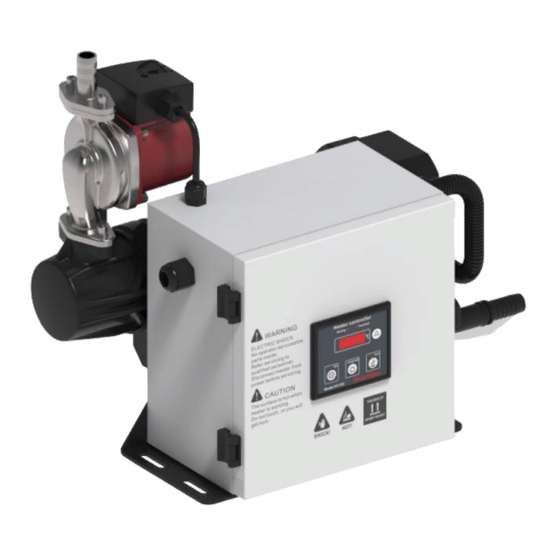
OVERVIEW HWP40-3/HWP60-3 forced circulation engine water heater is composed of 3 parts (control section, water pump and water heater). If the outside temperature is lower than 4ºC, engine coolant and lubricant may condense into solid state and lose their lubricating and cooling properties during cranking, which can damage the engine. -
Page 5: Specification
40L/min (1.5m of lift) Protection Level IP44 (5~8)Hz Amplitude±7.5mm Triaxial Vibration Resistance (8~500)Hz a=2g Triaxial Shock Resistance Half-sine wave =50g Triaxial peak Working Temperature -40ºC~+70ºC Storage Temperature -40ºC~+80ºC Case Dimensions 444mm×284mm×400mm Weight 18kg HWP40-3/HWP60-3 Forced Circulation Heater User Manual Page 5 of 11... -
Page 6: Heater Installation
Fig.1 – Installation Plane Schematic Diagram Fig.2 – Installation Side Schematic Diagram HWP40-3/HWP60-3 Forced Circulation Heater User Manual Page 6 of 11... -
Page 7: Operating Instructions
“Overheat” indicator is flashing. Temp. Display: OFF Temp. Display: ON Temp. Display: Current Temp. Alarm: Sensor Abnormal PANEL DESCRIPTION Fig.3 – Operation Panel Drawing HWP40-3/HWP60-3 Forced Circulation Heater User Manual Page 7 of 11... -
Page 8: Operation Description
After doing these, press button, the LED will back the current temperature. All the adjustment should be saved and not lost even when power is off. HWP40-3/HWP60-3 Forced Circulation Heater User Manual Page 8 of 11... -
Page 9: Use And Maintenance
Corresponding antifreeze is strongly recommended. Earth line must be soundly connected to earth. Drain valve: Can be opened or closed using hexagonal tools. Unit: mm Fig.5 – Water Drain Valve HWP40-3/HWP60-3 Forced Circulation Heater User Manual Page 9 of 11... -
Page 10: Connections
CONNECTIONS Fig.6 – HWP40-3/HWP60-3 Diagram Use 4mm power cable for tie-in. Earth line must be soundly connected to earth. HWP40-3/HWP60-3 Forced Circulation Heater User Manual Page 10 of 11... -
Page 11: Case And Dimensions
CASE AND DIMENSIONS unit: mm Fig.7 – Overall Dimensions NOTE: All the inlets/outlets connectors are pagoda-shape. _________________________________ HWP40-3/HWP60-3 Forced Circulation Heater User Manual Page 11 of 11...
Need help?
Do you have a question about the HWP40-3 and is the answer not in the manual?
Questions and answers