Panasonic SC-XH166GA Service Manual

Panasonic SC-XH166GA Service Manual

Dvd home theater sound system

Advertisement

Quick Links

SB-HFS4810
SB-HFS4010
Notes: Please refer to the original service manual for:
• Speaker system
SB-HFS4810/HFS4010/HC4010
SB-HW3010
SB-HC4010
SA-XH166
Order No:AD1403015CE
Order No:AD1403030CE
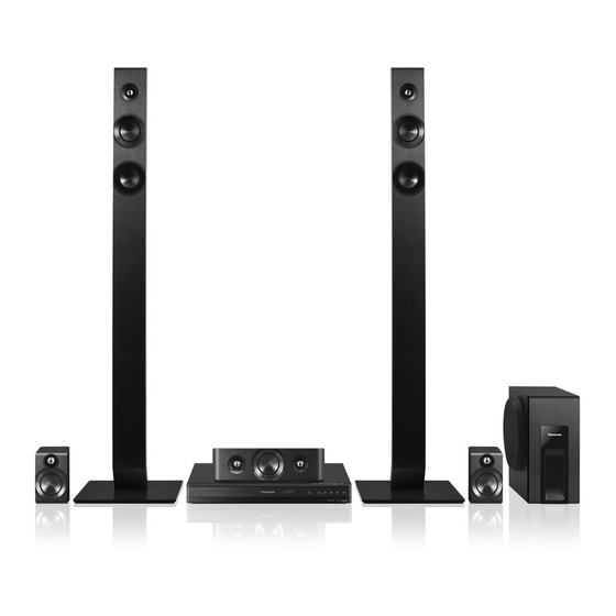
DVD Home Theater Sound System
Model No.
Remote
Control
SB-HW3010
Color: (K)...........Black Type
© Panasonic Corporation 2014
Unauthorized copying and distribution is a violation of law.
ORDER NO.AD1405024CE
SC-XH166GA
SC-XH166GS
SA-XH166GA
SA-XH166GS

Advertisement

Table of Contents
loading

Summary of Contents for Panasonic SC-XH166GA

  • Page 1 SB-HC4010 Control SB-HFS4810 SB-HFS4010 SA-XH166 SB-HW3010 Color: (K)...Black Type Notes: Please refer to the original service manual for: • Speaker system Order No:AD1403015CE SB-HFS4810/HFS4010/HC4010 Order No:AD1403030CE SB-HW3010 © Panasonic Corporation 2014 Unauthorized copying and distribution is a violation of law.
  • Page 2: Table Of Contents

    TABLE OF CONTENTS PAGE 1 Safety Precautions ------------------------------------------------3 1.1. General Guidelines ------------------------------------------3 1.2. Leakage Current Cold Check ------------------------------3 1.3. Leakage Current Hot Check (See Figure 1.) ----------3 1.4. Protection Circuitry -------------------------------------------3 2 Warning ---------------------------------------------------------------4 2.1. Prevention of Electrostatic Discharge (ESD) to Electrostatically Sensitive (ES) Devices ------------4 2.2.
  • Page 3: Safety Precautions

    1 Safety Precautions 1.1. General Guidelines 1. IMPORTANT SAFETY NOTICE There are special components used in this equipment which are important for safety. These parts are marked by in the Exploded Views and Replacement Parts List. It is essential that these critical parts should be replaced with manufacturer’s specified parts to prevent X-RADIATION, shock, fire, or other hazards.
  • Page 4: Warning

    2 Warning 2.1. Prevention of Electrostatic Discharge (ESD) to Electrostatically Sensitive (ES) Devices Some semiconductor (solid state) devices can be damaged easily by static electricity. Such components commonly are called Electrostatically Sensitive (ES) Devices. Examples of typical ES devices are IC(integrated circuits)and some field-effect transistors and semiconductor “chip”...
  • Page 5: Caution For Ac Cord (For The Saudi Arabia, Kuwait And Africa)

    A replacement fuse cover can be purchased from your local Panasonic Dealer. If the fitted moulded plug is unsuitable for the socket outlet in your home then the fuse should be removed and the plug cut off and disposed of safety.
  • Page 6: Precaution Of Laser Diode

    2.3. Precaution of Laser Diode CAUTION : This product utilizes a laser diode with the unit turned “on”, invisible laser radiation is emitted from the pick-up lens. Wave length:770 to 800 nm (CDs)/645 to 660 nm (DVDs) Maximum output radiation power from pick-up:100 μW/VDE Laser radiation from the pick-up lens is safety level, but be sure the followings: 1.
  • Page 7: Static Electricity Protection Measures

    2.4. Static Electricity Protection Measures • The laser diode in the traverse unit (optical pick-up) may break down due to potential difference caused by static electricity of clothes or human body. So, be careful of electrostatic breakdown during repair of the traverse unit (optical pick-up). 2.5.
  • Page 8: Service Navigation

    3 Service Navigation 3.1. Service Information This service manual contains technical information, which allow service personnels to understand and service this model. Please place orders with the part numbers in the parts list, not the numbers in the exploded views. If the circuit is changed or modified, the information will be followed by service manual to be controlled with original service manual.
  • Page 9 Step 4 Playback the CD-R disc or USB memory device by the DVD Theater. Set the CD-R disc or USB memory device into the DVD Theater and playback it. When the message of recommending the “Software Update” appears on the display monitor, select the Left cursor button: [Yes] or the Right cursor buttons :[No] and press the [OK] button with the remote control.
  • Page 10: Specifications

    4 Specifications GENERAL SPEAKER SECTION Woofer Full range Super tweeter Power consumption Approx. 41 W CONE TYPE (cm) CONE TYPE (cm) Piezo type Power consumption in Approx. 0.5 W Front standby mode Centre Power supply AC 220 V to 240 V, 50 Hz/60 Hz Surround Dimensions (W H D) 430 mm...
  • Page 11: Others (Licences)

    4.1. Others (Licenses) Manufactured under license from Dolby Laboratories. Dolby, Pro Logic, and the double-D symbol are trademarks of Dolby Laboratories. For DTS patents, see http://patents.dts.com. Manufactured under license from DTS Licensing Limited. DTS, the Symbol, & DTS and the Symbol together are registered trademarks, and DTS 2.0+Digital Out is a trademark of DTS, Inc.
  • Page 12: Location Of Controls And Components

    5 Location of Controls and Components 17 18 19...
  • Page 13 Turn the unit on and off Move the highlight for selection [OK] Turn the TV on and off Confirm the selection [AV, INPUT] [OPTION] Switch the input select of TV Show Option menu [SUBTITLE] [RETURN Change the subtitle settings. Return to previous screen [DVD], [USB], [RADIO], [AUX] [SOUND] Select an audio or video source...
  • Page 14: Installation Instructions

    Non-HDMI-compliant cables cannot of your TV supports be utilized. It is recommended that you ARC, skip Step 2. use Panasonic’s HDMI cable. When Vi d e o C a b l e outputting 1080p signal, please use HDMI Cable (Not supplied) HDMI cables 5.0 meters or less.
  • Page 15: Operating Instruction

    7 Operating Instruction 7.1. Take out the Disc from the Drive Unit when the Disc cannot be ejected by the OPEN/CLOSE button 7.1.1. When the Disc Eject can not be done. 1. Turn off the power and pull out the AC cord. 2.
  • Page 16: Troubleshooting Guide

    8 Troubleshooting Guide 8.1. About Operation of Set General operation Sound No sound. To return to the factory defaults. Low volume. Select “Restore” in “Default” in the Setup Distorted sound. menu. Cannot hear the desired audio type. Depending on the connected equipment, the To return all settings to the factory preset.
  • Page 17: About Circuit

    8.2. About Circuit Before the syptom check remove the power cable and reinsert it after 10 sec. If the unit is still NG, please refer to below syptoms. Symptom - 1 No Power Check the AC cord. Exchange the AC cord. (cutting or damage…etc) Check the Power supply Exchange the Fuse.
  • Page 18 Symptom - 2 No LED display /Keys do not work Check the Digital P.C.B. Exchange the Digital P.C.B. connector (XP82)*3 voltage. Check the FFC cable *4 Exchange the FFC cable. connecting Digital P.C.B. and Front panel P.C.B. Exchange the Front panel P.C.B. VOLTAGE DATA (measurement value) CHECK POINT LOCATION 5.1V...
  • Page 19 Symptom - 3 Can not OPEN or CLOSE Check the OPEN/ CLOSE Exchange the mechanism SW.(Break or click feeling…etc) Check the connector (XP135*5/ Check the symptom -1 XP136*6) voltage on the Digital P.C.B. Exchange the Mechanism unit. VOLTAGE DATA (measurement value) CHECK POINT LOCATION 1.5V 3.5V...
  • Page 20 Symptom - 4 No picture, No sound Check the k th Check symptom -3, Disc tray Operation. afterwards check (OPEN and COLSE) symptom -4. Check the Operation Check the connector and FL display. and FL display. (XP135*5) voltage on (XP135 5) voltage on 1.
  • Page 21: Wiring Connection And Voltage Data

    9 Wiring Connection and Voltage Data HDMI CVBS Speaker MECHANISM POWER UNIT SUPPLY P.C.B. AMP IC ADC AK5358A STA518 POWER 33V POWER 33V MOTOR HOME POWER 33V DRIVER SPHE8253RD-AT AM5890S RFGND SLED- SLED+ PSON RFGND TRAYIN FLASH XP82 XP82 XP221 XP221 NC 8 NC 8...
  • Page 22 SA-XH105GA/GS VOLTAGE DATA (measurement value) PIN NO. VALUE PIN NO. VALUE 5.1V 1.5V 3.5V 3.3V 2.6V PIN NO. VALUE 2.4V PIN NO. VALUE 3.3V 34.5V 34.5V PIN NO. VALUE 34.5V 5.1V 5.1V 2.7V 2.8V 3.0V 5.1V 5.1V...
  • Page 23: Disassembly And Assembly Instructions

    10 Disassembly and Assembly Instructions 10.1. Disassembly Flow Chart The following chart is the procedure of disassembling the casing and inside parts for internal inspection when carrying out the servicing. To assemble the unit, reverse the steps shown in the chart below. 1.
  • Page 24 10.3. Disassembly Procedure 10.3.2.2. Front Panel Unit 1. Disconnect the connector (A) and FFC cable. 2. Unlock 5 tabs (A) - (E). 10.3.1. Top Panel 3. Pull the Front Panel Unit in the direction (1). 1. Remove the 6 Black Screws. 2.
  • Page 25 10.3.4. Power Supply P.C.B. 10.3.6. Mechanism Unit 1. Disconnect the connector (A) and connect (B). 1. Remove 2 Screws (C) . 2. Remove 4 Screws (C) to remove the Power Supply P.C.B.. 2. Lift upward the Mechanism unit to remove it. (When assembling, first set the Mechanism unit to tabs (A) then tighten the 2 Screws (C).) Connector (A)
  • Page 26: Replacement Parts List And Exploded View

    11 Replacement Parts List and Exploded View 11.1. Replacement Parts List Notes: *Important safety notice: Components identified by mark have special characteristics important for safety. When replacing any of components, be sure to use only manufacture’s specified parts shown in the parts list. *Parts marked with [PJM] in the remarks column are supplied by PAVJM, others are supplied by PHK.
  • Page 27: Casing Parts & Mechanism Section

    11.2. Casing Parts & Mechanism Section...
  • Page 28: Packing & Accessories Section

    11.3. Packing & Accessories Section ACCESSORIES BAG A3 FM INDOOR ANTENNA AC CORD AC CORD FOR GA ONLY FOR GA & GS AC CORD OI BOOK HDMI CABLE FOR GS ONLY QSG OI SPEAKER CABLE PREPARATIOPN VER.) SPEAKER CABLE STICKER BATTERIES (NOT SUPPLIED) SCREWS (NOT SUPPLIED) SB-HW3010...

This manual is also suitable for:

Sc-xh166gsSa-xh166gaSa-xh166gs

Table of Contents