
Related Manuals for Foley AIR2G2-336

Summary of Contents for Foley AIR2G2-336
- Page 1 AIR2G2-336 OPERATOR MANUAL Model 3360901 & 3360902 With Touch Control Patent Pending ORIGINAL INSTRUCTIONS 3367901 (03-2022)
- Page 2 State of California to cause additional information, contact an authorized cancer, birth defects or other reproductive harm. Foley distributor and have the model and serial Battery posts, terminals, and related accessories numbers of your product ready.
-
Page 3: Table Of Contents
Table Of Contents Safety Locating the Tie-Downs Points Setup Hauling the Machine Product Overview Maintenance Specifications Maintenance Safety Operation Recommended Maintenance Schedule 19 Before Operation Safety Servicing the Air Cleaner Fuel Specification Removing the Filters Filling the Fuel Tank Installing the Filters Performing Daily Maintenance Checking the Engine-Oil Level During Operation... -
Page 4: Safety
General Safety This product is capable of causing personal injury. Always follow all safety instructions to avoid serious personal injury. • Read and understand the contents of this Manual before starting the engine. • Use your full attention while operating the machine. Do not engage in any activity that causes distractions; otherwise, injury or property damage may occur. - Page 5 CAUTION • Use great care when operating on inclines - 15 No fire or open flame degree maximum slope. • DO NOT RIDE ON EQUIPMENT. • REFER TO MANUAL: Read the user’s guide carefully before operating. Follow all operating and other instructions . Remove No Smoking key before service.
-
Page 6: Setup
Setup Loose Parts: Use the list below to verify that all parts have been shipped. Step Description Qty. Screw in to install under probes- wrench Pad Assembly provided in toolbox to tighten Oil And Air Filter 2 - quarts oil, 2 air filter Compressor oil and air filter The outside air cylinders are rotated for Rotate Cylinders... -
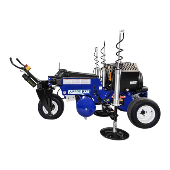
Page 7: Product Overview
Product Overview Forward (operating direction) Become familiar with all the controls before you start the engine and operate the machine. FUEL CAP TOUCH SCREEN TANK PRESSURE KEY SWITCH PROBE PRESSURE PROBE PRESSURE REGULATOR INJECT PRESSURE HANDLE INJECT PRESSURE REGULATOR TRIGGER BUTTONS EMERGENCY STOP MANUAL CANISTER... - Page 8 TANK, PROBE AND INJECT PRESSURE The tank pressure is the pressure in the air tank. The probe and inject pressures can be adjusted using the regulators. SYSTEM CUTOFF SWITCH AND KEY This is located on the right side of the machine just above the beam. Removing this key will disconnect the battery from the control.
-
Page 9: Specifications
Specifications Note: Specifications and design are subject to change without notice. Operating Temperature: • This equipment will operate correctly in its intended ambient temperature, at a minimum between +5C and +50C. Relative Humidity: • This equipment will operate correctly within an environment at 50% RH, +40C. Higher RH may be allowed at lower temperatures. -
Page 10: Operation
Operation Note: Determine the left and right sides of the machine from the normal operating position. Before Operation Before Operation Safety General Safety • Never allow children or untrained people to operate or service the machine. Local regulations may restrict the age of the operator. -
Page 11: Fuel Specification
Adding Fuel Fuel Specification • For best results, use only clean, fresh (less than30 days old), unleaded gasoline with an octane rating of 87 or higher ((R+M)/2 rating method). • Ethanol: Gasoline with up to 10% ethanol (gasohol) or 15% MTBE (methyl tertiary butyl ether) by volume is acceptable. -
Page 12: During Operation
During Operation During Operation Safety • The owner/operator can prevent and is responsible for accidents that may cause personal injury or property damage. • Wear appropriate clothing, including eye protection; long pants; substantial, slip-resistant footwear; and hearing protection. Tie back long hair, secure loose clothing, and do not wear loose jewelry. •... -
Page 13: Using The Machine
Installing Probes 1. Make sure machine is on a flat surface, brake is engaged and key is removed. IMPORTANT Never change probes with machine on. 2. Select the length of probe. Check the condition of the probe, do not use bent or worn probes. 3. -
Page 14: Screen Overview
Screen Overview When the key is turned to run, the screen will turn on. The MAINTENANCE screen will appear for a couple of seconds and then change to the Main screen. The Main screen will display the speed the machine is traveling at in MPH. -
Page 15: Programs
Screen Overview Injection Program Pressing the Inject button will bring you to the screen showing you the current inject setting. To change these setting press the CHANGE button (see next page for details) If the settings look correct then press the arrow. The SET PROBE PRESSURE and SET INJECT PRESSURE screens are there as a reminder to adjust the pressure before starting. -
Page 16: E-Stop
Screen Overview - Continued Pressing the CHANGE button on the Inject Settings screen bring you to the Setup Screen. There are 3 programs to select from depending on your needs. LIGHT is for areas that are regularly decompacted. STANDARD can be used for most applications. HEAVY should be used if the soil has never been decompacted or has compaction issues. -
Page 17: Setting Probe Pressure
Setting the Probe Pressure Use the PROBE PRESSURE REGULATOR to set the Probe pressure. This adjusts the pressure for the beam and the force that the probes will use to push into the ground. To adjust pull out on the knob and rotate clockwise to increase the pressure and counter clockwise to decrease the pressure. -
Page 18: After Operation
After Operation After Operation Safety • Park the machine on a level surface; and make sure the brake is engaged; shut off the engine; remove the key; and wait for all movement to stop before leaving the machine. • Keep all parts of the machine in good working condition and all hardware tightened. •... -
Page 19: Maintenance
• Ensure that all guards are installed, and the hood is secured shut after maintaining or adjusting the machine. • Use only Foley Company approved parts, warranty will be VOID if genuine approved parts are not used. Maintenance Schedule •... -
Page 20: Installing The Filters
Installing the Filters IMPORTANT To prevent engine damage, always operate the engine with the complete foam and paper air cleaner assembly installed. 1. Carefully slide the foam pre-filter onto the paper filter. 2. Place the air cleaner assembly onto the air cleaner base. 3. -
Page 21: Changing The Engine Oil And Filter
Changing the Engine Oil and Filter Service Interval: After the first 50 hours Every 100 hours—Change the engine oil and filter. Crankcase capacity: approximately 1.9 L (2.0 US qt) with the filter. 1. Start the engine and let it run for 5 minutes. This warms the oil so that it drains better. 2. -
Page 22: Fuel System Maintenance
Fuel System Maintenance DANGER Under certain conditions, fuel and fuel vapors are highly flammable and explosive. A fire or explosion from fuel can burn you and others and can cause property damage. • Fill the fuel tank outdoors, in an open area, when the engine is off and is cold. Wipe up any fuel that spills. •... -
Page 23: Electrical System Maintenance
Electrical System Maintenance Electrical System Safety • Disconnect the battery before repairing the machine. Turn off the cutoff Key and remove. Then Disconnect the negative terminal first and the positive last. Connect the positive terminal first and the negative last. •... -
Page 24: Checking The Fuses
Checking the Fuses The electrical system is protected by fuses. It requires no maintenance; however, if a fuse blows, check the component/circuit for a malfunction or short. 1. To replace fuses, pull out on the fuse to remove it. 2. Install a new fuse. Drive System Maintenance Checking the Tire Pressure Service Interval: Every 50 hours/Monthly (whichever comes first) - Page 25 Customer Support Contact Customer Support Foley Company 1750 Ryden RD Prescott, WI 54021 Call: 904-507-8900 Email: air2g2support@foleyco.com Facebook: facebook.com/FoleyCompany Twitter: @Foley_Company Scan on your mobile device to contact customer support ORIGINAL INSTRUCTIONS...
Need help?
Do you have a question about the AIR2G2-336 and is the answer not in the manual?
Questions and answers