Table of Contents
Advertisement
Quick Links
Advertisement
Table of Contents

Related Manuals for IHI Shibaura SR525HP-S

Summary of Contents for IHI Shibaura SR525HP-S
- Page 1 OPERATOR’S MANUAL OPRATOR’S MANUAL 取扱説明書 取扱説明書 SR525HP...
- Page 20 8.安全銘板の貼り付け位置 安全に作業していただくために、安全銘板の貼り付け位置を示したものです。 安全銘板は常に汚れや破損しないように保ち、もし破損・紛失した場合は、新しいものに張りなおしてくだ さい。 部品番号 名称 部品番号 名称 ① 390198260 コーションプレート(傾斜) ⑥ 390199790 コーションプレート ② A90630080 コーションプレート(回転刃) ⑦ 490992480 コーションプレート(バッテリ) ③ 390199780 コーションプレート(高圧油) ⑧ 490992470 コーションプレート(回転) ④ 390196910 コーションプレート(急停止) ⑨ 490992490 コーションプレート(ラジエタ) ⑤ 490992430 コウションプレート(給油) ⑩ 490992440 コーションプレート(マフラ)
- Page 21 安全銘板 機械を安全に使用していただくために、機械には安全銘板が貼られています。 それらの意味を下に説明しています。この取扱説明書の安全に関係する章を注意深く読むことを 推奨します。 1. 警告 1) 機械を使用する際は、取扱説明書をよく読み 安全に注意して行ってください。 2) 転倒のおそれがあるので20°以上の傾斜地 ① ④ ② ① で作業しないでください。 3) 点検整備時は、エンジンをストップさせ取扱 説明書を読んで行ってください。 ② 4) 不意に機械が動きひかれる駐車時は、駐車ブ ③ ⑤ レーキを掛けてください。 不意の起動により動き出した機械にひかれ るので、エンジンの始動は運転席からだけ行 ③ ④ ⑥ ってください。 5) 物が飛んで来たり、排ガスが出るので、機械 から安全な距離をとってください。 6) 巻き込まれてケガをするおそれがあるので、 エンジンまたは動力軸が回転中は体を近づけ ないでください。 2. 警告 ファンに巻き込まれて切断されるので、...
- Page 22 5. 危険 給油時に火を近づけると火災になるおそれがあ ります。 給油中は、エンジンを停止してください。 ディーゼル軽油専用です。 6. 警告 高圧オイルで障害を受けるので、 保守の手順は取 扱説明書を読んで行ってください。 7. 警告 保守点検は、 エンジンを止め取扱説明書にしたが って行ってください。 作動中は巻き込まれたり ・ 物が飛んでくる恐れが あるので注意してください。 8. 警告 傾斜地で作業する場合は、 強制4輪駆動で使用し てください。 強制4輪駆動にしないとタイヤがスリップして 滑落や転倒等の障害事故が引き起こす恐れがあ ります。...
- Page 23 9. 警告 急停車禁止 高速走行中、 或いは坂道での急停車は非常に危険 です。 急停車により転倒のおそれがあります。 10. 警告 火傷のおそれがあるので、 高温時には触らないで ください。...
- Page 24 エンジン番号 型式 ・ 製造番号 23 23...
- Page 31 アクセルレバー 駐車ブレーキ レバー レバーを下げてください。 メインブレーキ 前進ペダル 後進ペダル...
- Page 41 カバーフック...
- Page 43 カバー カバー カバーフック カバーフック グリップ...
- Page 55 0.35...
- Page 56 給油口...
- Page 57 ドレンプラグ レベルゲージ...
- Page 58 給油口 ドレンプラグ...
- Page 59 ドレンプラグ 給油口...
- Page 61 ドレンコック...
- Page 64 リヤアクスルピボット部...
- Page 65 カバー...
- Page 66 20×10.00-10...
- Page 67 メインブレーキ...
- Page 71 9080 0130 1050...
- Page 72 モデル SR525HP-S SR525HP-W 全長(mm) 2735 2760 作業時(mm) 2870 3155 全幅 移動時(mm) 2190 2320 機 体 全高(mm) 2000 寸 法 軸距(mm) 1600 前輪(mm) 1730 1790 軸距 後輪(mm) 1130 最低地上高(mm) 車 前輪サイズ 24 × 13.00 - 12 4PR 輪 後輪サイズ 20 × 10.00 - 10 4PR 形式名...
-
Page 80: Preface
Preface Be sure to read this Instruction Manual before starting operation of the mower. Thank you for your purchase of SHIBAURA Riding Reel Mower. This Instruction Manual describes how to handle the mower and precautions to be observed when operating it. Please read this manual carefully to understand the mower and handle it correctly. -
Page 81: Meaning Of Symbols (Danger, Warning, Caution, Caution For Handling, Reference)
Meaning of symbols Means that, if you do not observe the Danger warning, death or serious injury will result. Means that, if you do not observe the Warning warning, death or serious injury may result. Means that, if you do not observe the Caution caution, you may be injured. -
Page 82: Outline Of Manual
Outline of manual ● Describes important safety precautions for major work Section Be sure to observe items. Refer to respective item for required operation. Also for safe operation. describes details and location of each safety nameplate. Section Service and ● Describes the warranty form and after-sale services. -
Page 83: Table Of Contents
CONTENTS Preface Cautions ·································································································· 1 Notice ····································································································· 1 Meaning of symbols (Danger, Warning, Caution, Caution for handling, Reference) ·· 2 Object of mower ························································································ 2 Outline of manual ······················································································ 3 Section 1 Be sure to observe for safe operation 1. General precautions ······························································································ 7 2. - Page 84 Section 6 Operation and works 1. Running-in (initial 50 hours) ···················································································35 2. Starting and stopping the engine ·············································································35 3. Lifting and lowering the mower ···············································································36 4. Starting, turning and stopping ·················································································37 5. Mowing ··············································································································37 6. Loading on and unloading from truck ·······································································39 7.
- Page 85 CONTENTS 9. Inspecting the battery ···························································································62 10. Inspecting the pipes ·····························································································62 11. Inspecting the electric wiring ··················································································62 12. Greasing (supply) ································································································63 13. Inspecting and adjusting the fan belt ········································································64 14. Cleaning the radiator ····························································································64 15. Inspecting and replacing the fuse and fusible link ·······················································65 16.
-
Page 86: Section 1 Be Sure To Observe For Safe Operation
Section 1 Be sure to observe for safe operation ● Cautions described here are vital for your safety. You should observe these cautions without fail. ● If you do not observe these cautions, death, injuries, accidents, or damages of the machine may be caused. -
Page 87: Before Starting Operation
Section 1 Be sure to observe for safe operation 2. Before starting operation Warning Do not allow anybody other than the operator to get on the machine. Passenger capacity of this machine is one. Do not allow anybody other than the operator to get on it. -
Page 88: Inspections And Services Before And After Operation
Inspections and services before and after operation Danger Supply or replenish the oil when the engine is cold. Never supply or replenish the oil while the engine is running or hot. [If you do not observe these cautions:] The fuel may ignite and cause a fire hazard. ... - Page 89 Section 1 Be sure to observe for safe operation Warning Inspect or service the machine on a flat and stable surface. Chock the wheels on a flat and stable surface where the work is not prevented by the traffic or the machine does not fall down when inspecting or servicing the machine.
- Page 90 Warning Be careful for high pressure oil. Check the hydraulic couplings and hoses for looseness or damages constantly. Before removing the couplings and hoses, release the pressure in the hydraulic circuit. [If you do not observe these cautions:] High pressure oil may break your skin and cause injury. Caution ...
-
Page 91: Transporting The Machine
Section 1 Be sure to observe for safe operation 4. Transporting the machine Warning Do not operate the machine by inertia on the footboards. Operate the machine on a slope or footboards carefully. Avoid operate it by inertia with the speed change lever at the neutral position. -
Page 92: When Traveling Or Going Into Or Out Of A Field
5. When traveling or going into or out of a field Warning Prohibited traveling on general roads This machine has not acquired a sanction as a special-purpose car and cannot travel on general roads. [If you do not observe these cautions:] You may be punished due to violation of the Road Traffic Act. -
Page 93: Operation
Section 1 Be sure to observe for safe operation 6. Operation Warning Install or remove the implements on a flat surface. Install or remove the implements on a flat and stable surface. Illuminate properly in the night. [If you do not observe these cautions:] Accident may arise. - Page 94 Warning Do not get under the implement or tread the foot under the implement. Do not go or put out you foot underneath the implement. [If you do not observe these cautions:] When the implement lowers, you may be injured. ...
- Page 95 Section 1 Be sure to observe for safe operation Warning Do not drive the machine looking off or without holding on. [If you do not observe these cautions:] Injuries may result. When leaving the machine, stop the machine on a flat surface and stop the engine.
-
Page 96: After Completion Of Operation Or When Storing The Machine
7. After completion of operation or when storing the machine Danger Supply oil after the engine has cooled. Never supply oil while the engine is running or hot. [If you do not observe these cautions:] The fuel may catch fire and a fire hazard may arise. ... - Page 97 Section 1 Be sure to observe for safe operation Caution Be careful for high-pressure oil. Constantly check the hydraulic joints and hoses for looseness or damages. Before removing the joints or hoses, release the pressure in the hydraulic circuit. [If you do not observe these cautions:] High-pressure oil may break your skin, leading to an injury.
-
Page 98: Location To Stick Safety Nameplate
8.Location to stick safety nameplate Safety nameplates are attached to the machine as shown below to secure safe operation. Keep the safety nameplate unstained or broken. If broken or lost, replace with new ones. No. Parts No. Name No. Parts No. Name 390198260 Caution Plate (slope) - Page 99 SAFTY DECALS Your tractor must be used with care. Therefore, decals have been placed on the machine, to remind you pictorially of main precautions to take during use. Their meaning is explained below. We also strongly recommend to carefully read the safety instructions given in the concerned chapter of this manual.
- Page 100 4. DANGER Batteries produce explosive gas. Keep sparks and flames away. Battery contains sulfuric acid. Wear protective clothing and eye protection. 5. DANGER Use diesel fuel. Diesel fuel is flammable. Add diesel fuel before starting the engine. Never remove the fuel tank cap or add diesel fuel while the engine is running or when the engine is hot.
- Page 101 9. WARNING Do not depress the brake pedal quickly. Quick brake will cause upset of the machine. 10. WARNING Hot surfaces. To prevent injury, keep hands and body away from hot surfaces.
-
Page 102: Section 2 Service And Warranty
Section 2 Service and warranty 1. Keep the warranty form with care 2. Time limit for supply of repair parts The “Warranty Form” is required for repairs provided under the warranty. After reading the Time limit for the supply of repair parts for this warranty form, keep it with care. -
Page 103: Section 3 Names Of Components
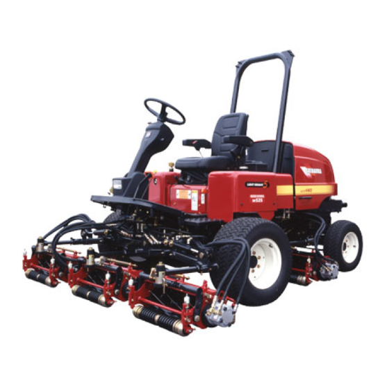
Section 3 Names of components 1. Main machine and operating units Brake Steering wheel Travel pedal Mower unit Mower unit Mower unit Front wheer tire Seat Fuel tank Oil tank Mower unit Mower unit Tool box Bonnet Rear wheel tire... -
Page 104: Mower Unit
Section 3 Names of components 2. Mower unit... -
Page 105: Section 4 Functions Of Operating Components
Section 4 Functions of operating components 1. Seat, switches and meters ① Seat The seat is provided with a flip-up arm rest. The seat position can be adjusted back and forth depending on the weight of the driver and reclined. ●... - Page 106 Section 4 Functions of operating components ② Steering wheel Height and angle of the steering wheel can be adjusted. ● Height adjustment By turning the knob counterclockwise, the height of the steering wheel can be freely adjusted. Turn the knob clockwise to fix the knob.
- Page 107 ③ Meters ⑤ Engine oil pressure lamp ① Hour meter This lamp lights up when the key switch is at The hour meter indicates the total operation the [ON] position. It goes out when the time. Carry out the periodical inspections and engine starts, the engine oil begins to services of the front mower according to this circulate and normal pressure is reached.
- Page 108 Section 4 Functions of operating components ④ Overheat/engine oil pressure ⑤ Key switch (operated by the right warning buzzer hand) The overheat/engine oil pressure warning buzzer warns rise of engine water temperature and drop of engine oil pressure. <Overheat warning> When the engine water temperature rises and the pointer of the water temperature meter reaches the [H] position, the warning buzzer...
-
Page 109: Pedals And Levers
2. Pedals and levers ● Parking brake (operated by the right hand) ① Accelerator lever (operated by the right hand) Accelerator lever Parking brake lever By stepping the main brake and pulling up the rod, the parking brake is applied. To release the brake, step the main brake strongly. -
Page 110: Control Box
Section 4 Functions of operating components ④ Speed change lever and 4-wheel ⑤ Implement lifting/lowering lever drive lever (operated by left hand) (operated by the right hand) Speed change lever Seat 4-wheel drive lever This lever is used to lift or lower the implement. ●... - Page 111 ② Lifting/lowering lever Warning Used to lift or lower the mower. Do not press the mowing button and lapping button at the same time. <While the cutting button lamp is out:> By pushing down the lever to the B auto side, the mower lowers and by pulling it up to the A lifting side, the mower rises only while the lever is being operated.
-
Page 112: Section 5 Inspections Before Operation And Work
Section 5 Inspections before operation and work Be sure to inspect the machine before starting operation and work. Danger Caution ● When inspecting, servicing or adjusting the ● Inspect or service the machine after the machine, be sure to stop the engine and muffler, engine and other hot parts have apply the parking brake. -
Page 113: Inspections
2. Inspections To secure safe and smooth work, the person using this machine should inspect the machine every day before starting operation in the following procedure. Repair troubles, if any, immediately. If any trouble is noticed during operation, check and service immediately. ①... -
Page 114: Section 6 Operation And Works
Section 6 Operation and works 1. Running-in (initial 50 hours) [Caution for handling] ● The self starter motor consumes a large Handling of a new vehicle in the initial 50 hours is current. Never operate it continuously for very important. Handling in this term may have more than 10 seconds. -
Page 115: Lifting And Lowering The Mower
① Starting the engine ② Stopping the engine ● By moving the accelerator lever to the [Low speed] position and turning the main switch to the [OFF] position, the engine stops. 3. Lifting and lowering the mower (1) Move the cock to the [Open] position. (2) Take the driver’s seat. -
Page 116: Starting, Turning And Stopping
Section 6 Operation and works 4. Starting, turning and stopping ② How to turn Warning Warning ● When starting the machine, give a sign to ● Before turning the machine, reduce the people around the machine, make sure of running speed sufficiently. If you turn keeping the safety and start the machine gently a high speed, the machine may turn avoiding sudden start. - Page 117 ① Cautions for operation of mower ④ Cutting speed (1) If you operate the mower for the first time, or Always keep the highest rotating speed of the not accustomed to the machine, learn how to cutting blades for smooth cutting operation. By operate on a flat surface before operating it.
-
Page 118: Loading On And Unloading From Truck
Section 6 Operation and works 6. Loading on and unloading from [ Work flow ] truck Warning Selection of operation ● When loading or unloading the machine onto or from the truck, place the truck on a flat surface not prevented by the traffic, stop the engine of the truck, apply the side brake and chock the wheels. -
Page 119: Power Steering
7. Power steering <Loading> (1) Lift up the implement. Caution (2) Load the implement gently in the straight direction to the footboards. ● While the engine is running, the steering (3) Operate the steering handle carefully not to wheel can be steered very lightly. Be careful allow the wheels to get out of the footboards. -
Page 120: Descriptions Of Decals
Section 6 Operation and works 8. Description of decals (Following decals are used for the front mower.) -
Page 121: Section 7 Care After Operation
Section 7 Care after operation 1. Care after operation 3. Cleaning the radiator (1) Pull down the front screen frontward. Danger ● When covering the machine with a sheet, stop the engine and confirm that the engine and muffler have completely cooled down. Otherwise, a fire may arise. -
Page 122: Care When Not In Use For A Long Time
Section 7 Care after operation 4. Care when not in use for a long time Warning ● When storing the machine, remove the battery and pull out the key and keep them in custody. Otherwise, an accident may result. When storing the vehicle for a long time (more than 1 month), service as follows before storing. -
Page 123: Section 8 Handling Of Mower
Section 8 Handling of mower 1. Removing the mower Warning ● Install or remove the mower on a flat and stable surface. In the night time, illuminate properly. Otherwise, an accident may result. ● When installing or removing the mower by moving the machine, do not permit a person to be around the machine or to get between the machine and mower. -
Page 124: Position Of No.4 And 5 Mowers For Maintenance
Section 8 Handling of mower 3. Positioning of No. 4 and 5 mowers for maintenance ● No.4 and 5 mowers can be positioned as shown below when servicing them for maintenance. (1) Position when changing the rear roller bracket and discharge cover positions (2) Turn the adjusting nuts (right and left) clockwise with a spanner and decrease the clearance between the rotary blades and... - Page 125 (2) Position when lapping ● To return to the original position, start the engine and move the lifting/lowering lever to ● Lower the reel on a flat and stable ground. the lifting side. When the reel unit lifted ● Pull out the L-shaped pin from the rolling above the ground, move the lifting/lowering arm.
-
Page 126: Adjusting The Cutting Height
Section 8 Handling of mower 4. Adjusting the cutting height ● Before adjusting the cutting height, align the rotary blades and lower blade. ● Adjust the cutting height for all of the 5 mower units. ● To cut the grass evenly to a required height, adjust the front and rear rollers. - Page 127 (3) Loosen the butterfly nut of the cutting height gauge nut, measure the clearance between the screw head bottom and gauge (below the screw neck) with a measure, adjust the size to the mowing height, and fix the screw tightening the butterfly nut. ●...
-
Page 128: Adjusting The Cutting Quality By Lapping (Grinding)
Section 8 Handling of mower 5. Adjusting the cutting quality by lapping (grinding) Warning ● Be sure to use the blade aligning fixture to rotate the rotary blade. ● Be sure to coat the rotary blade with abrasive using a brush. (1) Set the change-over valve levers to the stop side at 5 points. - Page 129 Move change-over valve lever gradually to the rotating side. The rotary blade starts to rotate. Adjust the rotating speed to a desired value with the lever. Keep grinding for some time. When the contact sound disappears, move the change-over valve to the stop side to stop rotating and stop the engine.
-
Page 130: Down Pressure Spring
Section 8 Handling of mower 6. Down pressure spring 7. Fixing the mower steering angle ● Each mower is provided with a down ● Steering angle of each mower is provided so pressure spring. The spring functions to keep that the damage on the turf at the time of the mower and ground always in contact with turning of the machine is reduced. -
Page 131: Section 9 Periodical Inspections And Services
Section 9 Periodical inspections and services Warning Every day inspections and services secure the machine performance and safe and smooth ● Periodical inspections and services should works. be performed in a place clear of traffic danger. In order to prevent troubles due to imperfect Place the machine on a flat and stable services of the machine, have it undergone ground not to allow the vehicle to fall down or... -
Page 132: Periodical Inspection List
Section 9 Periodical inspections and services 1. Periodical inspection list ○ Main machine Inspection ● Replacement Time on hour meter Refer ence page Inspection item Check every 5 hours after start of operation. Engine oil ● ● ● ● ● ●... -
Page 133: Oil And Water Supply List
3. Oil and water supply list Oil used maintenance E.O. item Diesel engine oil All season, SAE10W/30 Implement –5℃~25℃: SAE20W C.G. ① (reel) 10℃~35℃: SAE30 G.O. Cylinder C.C. ② HST oil, equivalent to ISO VG46 C.G. Lift arm C.G. ③ Chassis grease or universal Hydraulic oil grease No.2... -
Page 134: Checking The Fuel Level And Replenishing The Oil
Section 9 Periodical inspections and services 4. Checking the fuel level and 5. Checking and changing oil at replenishing the oil each part Danger Danger ● Do not replenish the fuel with a cigarette in ● Never supply oil while the engine is running the mouth or do not illuminate by an open or hot. - Page 135 [Cautions for handling] Removing the oil filler cap ● Check the oil level before the engine is started or when cold. ● Stop the machine on a horizontal surface and check the oil level at a horizontal condition. ● Never flow the exhaust oil to a river or sewage.
- Page 136 Section 9 Periodical inspections and services ③ Transmission oil ④ Rear axle oil Exchange the front transmission oil every 600 Change the rear axle oil every 600 hours. hours. Inspection Inspection Pull out the plug from the oil filler port on the left Oil filler port and level gauge are positioned above the rear axle, wipe the gauge top cleanly, under the seat.
-
Page 137: Replacing The Elements
6. Replacing the elements Changing the oil ① Engine oil element Drain the oil from the rear axle center, and right and left drain plugs under the rear axle. After The element is of the cartridge type. Replace the draining the oil completely, tighten the drain plug, element after 50 hours of operation first, and and supply new oil from the oil filler port on the then every 200 hours thereafter. - Page 138 Section 9 Periodical inspections and services ② Oil filter The oil filter is of the cartridge type. Replace the oil filter after 50 hours of operation first and then every 300 hours thereafter. (1) After draining the HST oil, turn the strainer in the hydraulic oil tank clockwise and remove.
-
Page 139: Inspecting And Changing The Cooling Water
7. Inspecting and changing the cooling water Danger ● Do not open the radiator cap while the engine is running or immediately after the engine stops. Stop the engine and wait until the engine has cooled down before opening the cap. Otherwise, hot water gushes out and you may be burnt. -
Page 140: Cleaning And Replacing The Air Cleaner Element
Section 9 Periodical inspections and services 8. Cleaning and replacing the air [Cautions for handling] ● When changing the cooling water, be sure to cleaner element add rustproof solution and idle the engine for The air cleaner removes sand from the air 5 minutes to facilitate the mixing of rustproof flowing in to prevent wear of the cylinder liner solution. -
Page 141: Inspecting The Battery
Warning 9. Inspecting the battery Danger ● Make sure that the battery level is between the upper and lower limits. Do not allow it to ● When inspecting or charging the battery, be under the lower limit. Otherwise, the pole never permit a fire near the battery. -
Page 142: Greasing (Supply)
Section 9 Periodical inspections and services 12. Greasing (supply) Inspect the grease condition every 50 hours. Also inspect the grease condition at each part before starting operation and supply grease as required. rear axle pivot... -
Page 143: Inspecting And Adjusting The Fan Belt
13. Inspecting and adjusting the fan belt Cautions ● Be sure to stop the engine. ● Inspect and adjust the fan belt when the engine is cold. Otherwise, you may be burnt. Open the rear cover, push the middle point of the fan belt by a force of about 10N (1kgf) to check that the belt deflection is about 4mm, and check for damage of the belt. -
Page 144: Inspecting And Replacing The Fuse And Fusible Link
Section 9 Periodical inspections and services 15. Inspecting and replacing the 16. Inspecting the tire fuse and fusible link ① Inspecting the tire Remove the fuse box cover and inspect the fuse. Check if the tire air pressure of front and rear If the fuse has blown out, replace with the one wheels is proper. -
Page 145: Inspecting And Adjusting The Brake
18. Inspecting and adjusting the brake Warning ● Check if the brake does not work improperly or unevenly. Otherwise, an accident may be caused. Step the brake pedal and check for the play as specified (15 – 20 mm) and simultaneous working on the right and left wheels. -
Page 146: Section 10 Diagnosis
Section 10 Diagnosis Section 10 Diagnosis Warning Warning ● If the engine does not work satisfactorily, be sure to stop the engine and diagnose referring to the list ● If the engine does not work satisfactorily, be sure to stop the engine and diagnose referring to the list below. -
Page 147: Brake
Condition Inspection item Remedy Too much engine oil Extract the oil down to proper amount. White smoke from muffler Too low engine oil viscosity Change the oil to one of proper viscosity. Reduced engine oil Replenish the oil to specified level. Engine oil pressure lamp Failed pressure switch Replace the switch. -
Page 148: Electrical
Section 10 Diagnosis 4. Electrical Condition Inspection item Remedy Burnt-out electric bulb Replace the bulb. Blown out fuse Replace the fuse. Lamp does not light up Wiring coming out of socket Check and set. (optional) Improper contact Check and clean the earth and terminal. -
Page 149: Section 11 Others
Section 11 Others 1. Major consumables Engine system Part code Name Q’ty/unit Remarks 1. Major consumables 080109061 Fan belt Engine 140517020 Oil filter Part code Name Quantity/unit Remarks 360720020 Fuel element Fuel 080109061 Fan belt Hydraulic, air cleaner and belt related parts 140517020 Oil filter Part code... -
Page 150: Specifications
Section 11 Others 3. Specifications Main machine Model SR525HP-S SR525HP-W Overall length (mm) 2735 2760 When working (mm) 2870 3155 Overall width When moving (mm) 2190 2320 Overall height (mm) 2000 Dimensions Wheel base (mm) 1600 Front (mm) 1730 1790 Wheel base Rear (mm) -
Page 151: Wiring Diagram
4. Wiring diagram Wiring diagram... - Page 152 Section 11 Others (2) Wiring diagram...
- Page 154 本社 長野県松本市石芝1-1-1 URL: http://www.ihi-shibaura.com HEAD OFFICE 1-1-1, Ishishiba , Matsumoto, Nagano, 390-8714 , Japan URL: http://www.ihi-shibaura.com Printed in Japan SR525HP A00810690 0712005-005 F...
Need help?
Do you have a question about the Shibaura SR525HP-S and is the answer not in the manual?
Questions and answers