Table of Contents
Advertisement
Quick Links
Operating Manual
Translation of the original operating manual
VAP 5 Vacuum Pumps
For vacuum drying oven VDL
Model
VAP 5 vacuum pump
VAP 5 vacuum pump
BINDER GmbH
Address: Post office box 102, 78502 Tuttlingen, Germany Phone: +49 7462 2005 0
Fax: +49 7462 2005 100 Internet: http://www.binder-world.com
E-mail: info@binder-world.com Service Hotline: +49 7462 2005 555
Service Fax: +49 7462 2005 93 555 Service E-Mail: customerservice@binder-world.com
Service Hotline USA: +1 866 885 9794 or +1 631 224 4340 x3
Service Hotline Asia Pacific: +852 390 705 04 or +852 390 705 03
Service Hotline Russia and CIS: +7 495 988 15 16
Voltage
Equipment
230 V
4 heads
120 V
4 heads
Art. no.
5013-0220
5013-0221
Advertisement
Table of Contents
Troubleshooting

Related Manuals for Binder VAP 5


Summary of Contents for Binder VAP 5
- Page 1 Fax: +49 7462 2005 100 Internet: http://www.binder-world.com E-mail: info@binder-world.com Service Hotline: +49 7462 2005 555 Service Fax: +49 7462 2005 93 555 Service E-Mail: customerservice@binder-world.com Service Hotline USA: +1 866 885 9794 or +1 631 224 4340 x3 ...
-
Page 2: Table Of Contents
Pictograms in this manual ......................8 Localization / position of safety labels on the device ................9 Type plates and classifications ......................10 1.5.1 Type plate of the entire device VAP 5 ..................10 1.5.2 Type plate of the electric motor ....................12 1.5.3 Type plate of the mechanical pump unit ................. - Page 3 Area classification in the surroundings of the VAP 5 vacuum pump ........38 3.4.3 Area classification in the surroundings of the VAP 5 vacuum pump when setting it up in the pump module (optional) ......................39 COMPLETENESS OF DELIVERY, TRANSPORTATION, STORAGE, AND INSTALLATION ....................
- Page 4 Function test ........................... 75 11.5 Simple troubleshooting ........................75 11.6 BINDER Service contact data ......................77 11.7 Sending a device back to BINDER GmbH ..................77 12. DISPOSAL......................77 12.1 Disposal of the transport packing ...................... 77 12.2 Decommissioning ..........................78 12.3 Disposal of the device in the Federal Republic of Germany .............
-
Page 5: Operating Manual And Classification
Operating Manual. This Operating Manual is supplemented and updated as needed. Always use the most recent version of the Operating Manual. When in doubt, call the BINDER Service Hotline for information on the up-to- dateness and validity of this Operating Manual. -
Page 6: Legal Considerations
In no event shall BINDER be held liable for any damages, direct or incidental arising out of or related to the use of this manual. -
Page 7: Structure Of The Safety And Warning Notices
1.3.3 Safety alert symbol Use of the safety alert symbol indicates a risk of injury Observe all measures that are marked with the safety alert symbol in order to avoid death or injury. VAP 5 02/2022 Page 7/94... -
Page 8: Explosion Protection Symbol
Release before Mandatory regulation Read operating Disconnect the power maintenance or repairs instructions plug Wear protective gloves Wear eye protectors Ground before use Wear ESD shoes (antistatic shoes) Environment protection Wipe with damp cloth only VAP 5 02/2022 Page 8/94... -
Page 9: Localization / Position Of Safety Labels On The Device
Safety labels (warning signs) Hot surface Figure 1: Position of the safety labels on the device Keep safety labels complete and legible. Replace safety labels that are no longer legible. Contact BINDER service for these replacements. VAP 5 02/2022 Page 9/94... -
Page 10: Type Plates And Classifications
There are three type plates / four classification labels on the device in the following positions: Figure 2: Type plate positions Entire device (assembly) Pump unit Motor 1.5.1 Type plate of the entire device VAP 5 230V 115V Figure 3: Type plate of the entire device VAP 5 (assembly) VAP 5 02/2022 Page 10/94... - Page 11 Indications of the type plate of the entire device VAP 5 Indication Information BINDER Manufacturer: BINDER GmbH Vacuum pump Device name: Vacuum pump VAP 5 Model designation Serial-No. Serial no Ex classification according to ATEX Directive 2014/34/EU II 2/3/- G IIB T4 Gb/Gc/- X P <...
-
Page 12: Type Plate Of The Electric Motor
Figure 4: Type plate of the electric motor 1.5.3 Type plate of the mechanical pump unit Figure 5: Type plate of the mechanical pump unit 1.5.4 Classification on the cable gland Figure 6: Cable gland with Ex classification VAP 5 02/2022 Page 12/94... -
Page 13: Ex Classification Of The Device And Immediate Surroundings
The VAP 5 vacuum pump is an assembly in the sense of ATEX Directive 2014/34/EU with the following Ex classification: II 2/3/- G IIB T4 Gb/Gc/- X in accordance with DIN IEC 60079-46. -
Page 14: Parts Of The Assembly "Vap 5 Vacuum Pump
1.6.2 Parts of the assembly “VAP 5 vacuum pump” The “VAP 5 vacuum pump” assembly includes the following parts in the sense of the ATEX directive 2014/34/EU: Component with a classification... -
Page 15: Safety
The operator must ensure that the personnel are properly trained and that all necessary protective measures are complied with. GEFAHR Hazards during activities by untrained personnel. Serious injuries and device damage. Risk of death. Follow the instructions on personnel qualification in this operating manual. VAP 5 02/2022 Page 15/94... - Page 16 Daily inspection Regular inspection Testing before commissioning Testing after maintenance / repair Cleaning Decontamination of the external surfaces of the pump and the glass attachments Decontamination after use of X (depending on the hazardous substances application) VAP 5 02/2022 Page 16/94...
-
Page 17: Intended Use
Area of application The VAP 5 vacuum pump is used to extract gaseous media, in particular from the BINDER VDL vacuum drying ovens. It is suitable for pumping flammable solvents up to an ignition temperature of 200 °C as well as non-flammable solvents. - Page 18 According to IEC 60079-0 the VAP 5 vacuum pump is NOT intended for the temperature classes T4, T5 and T6. Insert only substances with an auto-ignition temperature that is higher than 200 °C / 392 °F.
- Page 19 / permanently have potential explosive atmospheres. The EX labelling must be observed, see chap. 1.6. The device plug (power plug) is not explosion-proof. The electrical connection must therefore be located outside a zone. VAP 5 02/2022 Page 19/94...
-
Page 20: Foreseeable Misuse
• Continued operation of the device during an obvious malfunction • Insertion of objects, particularly metallic objects, in louvers or other openings or slots on the device • Human error (e.g. insufficient experience, qualification, stress, exhaustion, laziness) VAP 5 02/2022 Page 20/94... -
Page 21: Residual Risks
• Contact with live parts in normal state • Operation without supervision Cleaning and Decontamination • Explosive atmosphere during cleaning and decontamination • Electrostatic charges • Penetration of water into the device • Inappropriate cleaning and decontamination agents VAP 5 02/2022 Page 21/94... -
Page 22: Operating Instructions
• Absence of a plausibility check to rule out erroneous inscription of electrical components • Performance of repair work by untrained/insufficiently qualified personnel • Inappropriate repairs which do not meet the quality standard specified by BINDER • Use of replacement parts other than BINDER original replacement parts •... -
Page 23: Safety Instructions On Installation
In the event of potential safety hazards, these must be assessed and measures must be taken to avert them. BINDER GmbH is responsible for the safety features of the device only, provided skilled electricians or qualified personnel authorized by BINDER perform all maintenance and repair, and if components relating to device safety are replaced in the event of failure with original spare parts. -
Page 24: Technical Ventilation
Strictly observe the relevant legal regulations about how to select an appropriate location. When setting up the VAP 5 vacuum pump in the optional pump module: Avoid the solvent accumulation in the optional pump module as this would cause the vacuum module to become an occasionally or continuously / for long periods / frequently potentially explosive area (Zone 0 or 1). -
Page 25: Equipotential Bonding According To The Grounding Concept
Accessibility to the disconnection from the power supply To completely separate the VAP 5 vacuum pump from the power supply, you can disconnect it from the power supply turning off the main power switch (7). Install the device in a way that the main power switch(red off switch)is easily accessible and can be easily reached in case of a danger. -
Page 26: Safety Instructions On Operating The Vacuum Pump
Danger of burning when touching the hot inner surfaces during operation. Burns. ∅ Do NOT touch the motor housing and surrounding areas during and after operation. Do NOT touch the motor housing and surrounding areas when operating the main power switch. VAP 5 02/2022 Page 26/94... -
Page 27: Measures Against Hazards From Cold Surfaces
2.6.3.4 Observe the maximum gas suction temperature The VAP 5 vacuum pump is designed for a gas inlet temperature of 40 °C / 104 °F max. Do NOT exceed this temperature. The temperature of the gases and vapors aspirated must not exceed the allowable suction temperature of 40 °C when entering the pump. -
Page 28: Measures Against Condensation By Pumping Vapors
Risk of injury due to Bursting due to sudden aeration. Injuries. Check the pressure before disconnecting the pneumatic connections Only use the vacuum-proof and shatter-proof glass apparatus supplied. Even when the pump is switched off, there may still be a vacuum! VAP 5 02/2022 Page 28/94... -
Page 29: Safety Instructions On Inert Gas Supply
Fire and explosion hazard caused by chemical reactions with changes in pressure. Serious injury or death from burns and / or explosion pressure. Make sure that no dangerous chemical reactions of the aspirated media can occur in the vacuum pump. VAP 5 02/2022 Page 29/94... -
Page 30: Operator Responsibility, Documentation, And Measures
They should also minimize the spread of an explosion and its effects. (ATEX operator directive 1999/92/EG) The explosion protection document serves to document the results of the risk assessment in accordance with § 6 Para. 9 GefStoffV (for Germany). VAP 5 02/2022 Page 30/94... -
Page 31: Employee Training And Protocols
Safety Regulation (BetrSichV); Ordinance on Hazardous Substances (GefStoffV)). Keep these operating instructions with the device at all times in a place where they are clearly visible. They must be comprehensible and written in the language of the employees. VAP 5 02/2022 Page 31/94... -
Page 32: Personal Protective Equipment
The following contents should be entered and recorded: • Solvent type • Solvent auto-ignition temperature; in the case of solvent mixtures: solvent with the lowest Auto-ignition temperature • Drying temperature • Date • Signature VAP 5 02/2022 Page 32/94... -
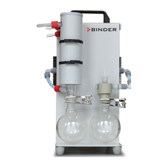
Page 33: Device Description
Device description Device overview (10) (11) (12) (13) Figure 8: VAP 5 vacuum pump, front (Illustration without equipotential bonding cable) Carrying handle Pneumatic inlet connection (suction side) Conical joint clip Emission condenser Separator(suction side) Condensate catchpot (pressure side) On/Off switch (main switch) On switch “green” / Off switch “red”... - Page 34 (16) (17) (14) Vacuum pump with connections Drive chamber of the pump unit Figure 9: VAP 5 vacuum pump, rear (Illustration without equipotential bonding cable) (14) Power cord (15) Inert gas connection outlet* for purging the drive chamber(chap. 6.4.1) (16) Inert gas connection inlet* for purging the drive chamber(chap.
-
Page 35: Description And Equipment
Installation site The VAP 5 vacuum pump may be installed in areas in which explosive atmospheres may occur on a rare and temporary basis. The entire device with the exception of the power plug is classified in category 3 in relation to the environment. -
Page 36: Manufacturer's Safety Plan: Protective Measures And Equipment
There is a safety valve (13) on the gas inlet of the emission condenser. If the pressure side is closed by deposits, the safety valve opens due to the overpressure. The medium is thereby released from the device. Check the valve seals at regular intervals. VAP 5 02/2022 Page 36/94... - Page 37 The establishment of equipotential bonding of the system in accordance with the manufacturer's grounding concept is mandatory. You can find a detailed grounding concept for the VDL, the pump module, the VAP 5 vacuum pump and installation and loading area is provided in the operating manual of the VDL vacuum drying oven, chap.
-
Page 38: Area Classification, Information For The Zone Classification
Area classification in the surroundings of the VAP 5 vacuum pump The VAP 5 vacuum pump, with the exception of the power plug, is classified in category 3 in relation to the environment. It may be installed in areas in which explosive atmospheres may occur on a rare and temporary basis. -
Page 39: Area Classification In The Surroundings Of The Vap 5 Vacuum Pump When Setting It Up In The Pump Module (Optional)
Never (unprotected areas): Connection location of the power plug. The spread of an explosive atmosphere to unprotected device parts must be reliably prevented. 3.4.3 Area classification in the surroundings of the VAP 5 vacuum pump when setting it up in the pump module (optional) -
Page 40: Completeness Of Delivery, Transportation, Storage, And Installation
Scope of delivery VAP 5 vacuum pump, with pump unit, housing, motor, and glass attachments • Pump connection with small flange DN 16 (nominal width) • 2 glass flasks (separator and condensate catchpot), • 2 fork clamps (conical ground clamps) for the condensate catchpot and separator •... -
Page 41: Guidelines For Safe Transportation
Note on second-hand devices (Ex-Demo-devices): Second-hand devices are devices that were used for a short time for tests or exhibitions. They are thoroughly tested before resale. BINDER ensures that the devices is technically sound and will work flawlessly. Second-hand devices are marked with a sticker as such. Please remove the sticker before commissioning the device. -
Page 42: Storage
Observe all safety and warning information. Set up the VAP 5 vacuum pump oven on a flat, even and non-flammable surface, free from vibration, in a well-ventilated, dry location and align it using a spirit level or laser. The site of installation must be capable of supporting the device’s weight (see technical data, chap. -
Page 43: Information On Equipotential Bonding
The VAP 5 vacuum pump is not intended for installation in a Zone 1 or 0. It must not be installed or operated in an occasionally or continuously / for long periods / frequently potentially explosive area. Measures must be taken to prevent the spread of explosive atmospheres to unprotected areas. -
Page 44: Accessibility Of The Main Power Switch / Emergency Stop
Follow country-specific regulations for explosion protection. With the optional pump module, the VAP 5 vacuum pump will be delivered in a separate box and must be fitted into the module and connected at the place of installation (chap. 6). -
Page 45: Lightning Protection Device
Lightning protection device The building in which the VAP 5 vacuum pump is installed must have a lightning protection system. All internal connections in the operator's building must contain lightning protection in accordance with EN/IEC 62305-3. Lightning protection measures must be taken in order to prevent melting and spraying effects. The operator’s zone classification shall be used to plan lightning protection measures. - Page 46 Serious injury or death from burns and / or explosion pressure. Ensure that the grounding cable remains fitted to the vacuum connection. Check that the grounding cable is firmly attached after connection VAP 5 02/2022 Page 46/94...
-
Page 47: Coolant Connection
They are colorless and almost odorless and therefore practically imperceptible. Inhalation of inert gases can cause drowsiness up to respiratory arrest. When the content of the air decreases below 18%, there is risk of death from lack of oxygen. VAP 5 02/2022 Page 47/94... -
Page 48: Inert Gas Connections For Purging The Drive Chamber
It is the responsibility of the operator to ensure and monitor purging. The inert gas is fed in at the inert gas connection inlet (16) of the drive chamber and is discharged via the inert gas connection outlet (15) of the drive chamber. VAP 5 02/2022 Page 48/94... - Page 49 Make sure that flow monitoring is active at the inert gas connection outlet (15) of the drive chamber. If the flow rate changes, switch off the pump immediately. Determine the cause and rectify it. VAP 5 02/2022 Page 49/94...
-
Page 50: Gas Ballast Inert Gas Connection
• Remove and retain the screw plug and seal from the connector (17). • Screw in the supplied hose shaft DN 8 with seal in a gas-tight manner. • Attach the inert gas supply hose • Secure the attached hoses with a hose clamp VAP 5 02/2022 Page 50/94... -
Page 51: Achieving Equipotential Bonding / Grounding Concept
Equipotential bonding to metal clamp (small Equipotential bonding to the carrier of the glass flange clamp) on pneumatic inlet (suction side) attachments and to the housing of the pump unit Figure 21: Equipotential bonding cable on the pump (symbolic illustration) VAP 5 02/2022 Page 51/94... -
Page 52: Connection To The Equipotential Bonding Of The System (By The Customer)
Do not loosen or remove any of the existing grounding connections! Figure 22: Grounding connection (9) The fastening material is enclosed with the unit as a (delivery condition) for attachment grounding kit (chap. 4.1). of an equipotential bonding cable VAP 5 02/2022 Page 52/94... - Page 53 Before commissioning, measure the equipotential bonding after first setting up the vacuum pump and implementing all described measures for establishing the equipotential bonding Provide cyclic measurements of the equipotential bonding. Always wear ESD-protected safety clothing when operating the device. VAP 5 02/2022 Page 53/94...
-
Page 54: Electrical Connection
• Only use original connection cables from BINDER according to the above specification. • Prior to connection and start-up, check the power supply voltage. Compare the values to the specified data located on the type plate of the vacuum pump, chap. -
Page 55: Explosion Safety Tests
See also electrical data (chap.13.1). To completely separate the VAP 5 vacuum pump from the power supply, you can disconnect it from the power supply turning off the main power switch (7). Install the device in a way that the main power switch (red off switch) is easily accessible and can be easily reached in case of a danger. -
Page 56: Explosion Protection Plan
Ex system. Equivalent test results according to other legal regulations can be considered. It is also permissible to refer to tests that have already been carried out. VAP 5 02/2022 Page 56/94... -
Page 57: Inspection After Changes Requiring Review
Recurring tests for the explosive safety of the system Objective of testing: The recurring tests serve to maintain the explosive safety of the Ex system. Among other things, the actual state of the system is compared VAP 5 02/2022 Page 57/94... -
Page 58: Commissioning
• The personal protective equipment (PPE) of the operating personnel must be implemented ESD protected, i.e. against electrostatic discharge. • Only trained personnel with password authorization may work on the VAP 5 vacuum pump. • All required tests must be carried out. -
Page 59: Turning On And Off, Emergency Stop
Turning on and off, emergency stop Turning on Turn on the VAP 5 vacuum pump at the main power switch (7) by pressing the green button (7). Main power switch Switch off: red button Switch on: green button... -
Page 60: Operation
Operation With regard to operating the VAP 5 vacuum pump and further elements of the system, please observe the relevant local and national regulations (for Germany in particular: DGUV guidelines 213-850 on safe working in laboratories, issued by the employers’ liability insurance association; Industrial Safety Regulation (BetrSichV);... - Page 61 The time interval and the procedure for emptying must be determined by the operator. Safe emptying must be ensured. (18) (19) (18) Figure 25: Removing the condensate catchpot (6) Separator (suction side) Condensate catchpot (pressure side) (18) Knurled screws (19) Conical joint clips VAP 5 02/2022 Page 61/94...
-
Page 62: Cleaning And Decontamination
Make sure that no water will enter into slots or openings on the device. Before cleaning, disconnect the power plug. Let the device cool down to ambient temperature. Completely dry the device before turning it on again. Avoid electrostatic charges. VAP 5 02/2022 Page 62/94... -
Page 63: Cleaning
Form diaphragm Do not use cleaning agents that may cause a hazard due to reaction with components of the device or the aspirated material. If there is doubt regarding the suitability of cleaning products, please contact BINDER service. VAP 5 02/2022... -
Page 64: Decontamination / Chemical Disinfection
Any corrosive damage that may arise following use of other cleaning agents is excluded from liability by BINDER GmbH. Any corrosive damage caused by a lack of cleaning, is excluded from liability by BINDER GmbH. NOTICE Danger of corrosion by using unsuitable cleaners. -
Page 65: Pump Suction Chamber Decontamination
For chemical disinfection, we recommend using the disinfectant spray Art. No. 1002-0022. Any corrosive damage that may arise following use of other disinfectants is excluded from liability by BINDER GmbH. With every decontamination method, always use adequate personal safety controls. -
Page 66: Maintenance And Service, Troubleshooting, Maintenance By The Operator, Repair, Testing
• Repair by the manufacturer Repair of the device must only be performed by BINDER Service or by BINDER qualified service partners or technicians. Procedure for returning the device to BINDER GmbH, see chap. 11.7 After maintenance, the device must be tested prior to resuming operation. -
Page 67: Safety Instructions
Only open the device when the power plug is disconnected. ∅ Make sure that general maintenance work will be conducted by licensed electricians with additional skills in explosion protection (ATEX) or experts authorized by BINDER. DANGER Electrical hazard due to high voltage after improper repairs. -
Page 68: Regular Inspection, Maintenance Intervals
• If necessary, replace the seals (usually together with membrane replacement, chap. 11.4) • Check all connections for tightness • Check the glass apparatus for integrity • Check the device for functionality and deviations, e.g. abnormal operating noise • Clean the device regularly (chap. 10.1) VAP 5 02/2022 Page 68/94... -
Page 69: Maintenance Intervals
• Restoration of safe operating condition (assembly, installation, equipotential bonding, tests. Only carry out the work described here that is permissible for the operator. All other maintenance or service work may only be carried out by the manufacturer or authorized specialist personnel. VAP 5 02/2022 Page 69/94... -
Page 70: Removing The Pump Unit From The Housing
• Disconnect the power supply and secure it against being switched on again. • Loosen and remove the pneumatic connection to the pump • Place the device in a way that the back side is facing up VAP 5 02/2022 Page 70/94... - Page 71 • Remove the pump unit from the housing • Disconnect the equipotential bonding at the pump unit Pump unit with motor removed, front view (equipotential bonding cable is not shown) VAP 5 02/2022 Page 71/94...
-
Page 72: Removing The Equipotential Bonding Cable
Before changing the maintenance kit, the following steps must be carried out: Removing the glass attachments and emptying the separator and condensate catchpot (chap. 9.2). • Disconnect the power supply and secure against reconnection • The pump unit must be removed from the carrier (chap. 11.4.1) VAP 5 02/2022 Page 72/94... - Page 73 • Check whether you can easily rotate the drive. Figure 27: Disassembly and assembly of the pump unit Pneumatic connection Cylinder screws Form diaphragm Compression fittings Pump head Valves O-rings (22 x 2) O-rings (28 x 2) Valve inserts Heat dissipater VAP 5 02/2022 Page 73/94...
-
Page 74: Reinserting The Pump Unit Into The Housing
Explosion hazard by electric sparking due to missing or improperly implemented equipotential bonding. Serious injury or death from burns and / or explosion pressure. Before commissioning, ensure that all equipotential bonding cables are connected and that all measures for equipotential bonding are observed. VAP 5 02/2022 Page 74/94... -
Page 75: Function Test
Resetting the thermal switch The VAP 5 vacuum pump is equipped with a fitted with a thermal protection switch on the motor. This self- retaining bimetal switch disconnects the entire unit from the power supply in the event of overheating. - Page 76 Pump unit drive blocked Replace diaphragm (chap. 11.4). Motor defective. Contact BINDER service. Pump unit drive defective. Contact BINDER service to have the Power cable broken or brittle cable replaced. Vacuum Pneumatic connections / Determine and seal the leak, if connections leaking.
-
Page 77: Binder Service Contact Data
11.7 Sending a device back to BINDER GmbH you return a BINDER product to us for repair or any other reason, we will only accept the product upon presentation of an authorization number (RMA number) that has previously been issued to you. An authorization number will be issued after receiving your complaint either in writing or by telephone prior to your sending the BINDER product back to us. -
Page 78: Decommissioning
(Elektro- und Elektronikgerätegesetz, ElektroG from 20 October 2015, BGBl. I p. 1739) or contact BINDER service who will organize taking back and disposal of the device according to the German national law for electrical and electronic equipment (Elektro- und Elektronikgerätegesetz, ElektroG from 20 October 2015, BGBl. -
Page 79: Disposal Of The Device In The Member States Of The Eu Except For The Federal Republic Of Germany
According to Annex I of Directive 2012/19/EU of the European Parliament and of the Council on waste electrical and electronic equipment (WEEE), BINDER devices are classified as “monitoring and control instruments” (category 9) only intended for professional use”. They must not be disposed of at public collecting points. -
Page 80: Disposal Of The Device In Non-Member States Of The Eu
Drive chamber purging inlet/outlet Hose shaft DN 8 (inner diameter 8 mm) (Scope of delivery for inert gas connection) Gas ballast Hose shaft DN 8 (inner diameter 8 mm) (Scope of delivery for inert gas connection) VAP 5 02/2022 Page 80/94... -
Page 81: Vap 5 Technical Data
13.2 VAP 5 Technical data Device type 230 V model 120 V model Dimensions Height 530 ± 10 530 ± 10 Width 330 ± 10 330 ± 10 Depth 360 ± 10 360 ± 10 Weight (unpackaged) 28,2 28,2 Performance data at 50 Hz Suction capacity acc. -
Page 82: Materials Of Pump Parts In Contact With The Medium
Connection block incl. hose shaft 13.5 Accessories and spare parts BINDER GmbH is responsible for the safety features of the device only, provided skilled electricians with additional skills in explosion protection or qualified personnel authorized by BINDER perform all maintenance and repair, and if components relating to device safety are replaced in the event of failure with original spare parts. -
Page 83: Diagrams Of Suction Pressure / Suction Capacity
13.6 Diagrams of suction pressure / suction capacity Suction pressure – p [mbar] Figure 28: Characteristic suction capacity S (p) of the VAP 5 vacuum pumps 13.7 Dimensions Device view, front Device view, left side Figure 29: VAP 5 dimensions Height 330 ±... -
Page 84: Certificates And Declarations Of Conformity
Certificates and declarations of conformity 14.1 EU Declaration of conformity VAP 5 02/2022 Page 84/94... - Page 85 VAP 5 02/2022 Page 85/94...
- Page 86 VAP 5 02/2022 Page 86/94...
-
Page 87: Damage Report
After consultation, cleaning can be carried out by the manufacturer The completed Contamination clearance certificate (chap. 16) form must be sent in by fax or letter before sending in the device. VAP 5 02/2022 Page 87/94... - Page 88 A repair can only be carried out if a fully completed damage report and a fully completed contamination clearance certificate are available. Otherwise, work may be delayed. Our general terms and conditions of delivery and payment apply. Notes/additions VAP 5 02/2022 Page 88/94...
-
Page 89: Contamination Clearance Certificate
Details about utilized substances / biological substances / or process-related reaction products which came into contact with the unit / components Commercial name / Product name / Manufacturer Chemical name Danger class Safety measures required for handling these substances: VAP 5 02/2022 Page 89/94... - Page 90 We are aware that, in accordance with Article 823 of the German Civil Code (BGB), we are directly liable with regard to third parties, in this instance especially the employees of BINDER GmbH, who have been entrusted with the handling / repair of the unit / component.
- Page 91 For service and maintenance on site, such a contamination clearance certificate must be submitted to the service technician before the start of any work. No repair or maintenance of the equipment is possible, without a properly filled out contamination clearance certificate. Notes/additions VAP 5 02/2022 Page 91/94...
-
Page 92: For Devices In The Usa And Canada
Yes No Yes No Pictures have to be attached! Pictures of device attached? Yes No Pictures of Packaging attached? Customer Contact Information Distributor Contact Information Name Company Address Phone E-mail VAP 5 02/2022 Page 92/94... - Page 93 Safety measures required for handling the list under 3.1 ____________________________________________________________________________ ____________________________________________________________________________ ____________________________________________________________________________ Measures to be taken in case of skin contact or release into the atmosphere ____________________________________________________________________________ ____________________________________________________________________________ ____________________________________________________________________________ ____________________________________________________________________________ Other important information that must be considered ____________________________________________________________________________ ____________________________________________________________________________ ____________________________________________________________________________ VAP 5 02/2022 Page 93/94...
- Page 94 4.5 Shipping laws and regulations have not been violated. I hereby commit and guarantee that we will indemnify BINDER Inc. for all damages that are a consequence of incomplete or incorrect information provided by us, and that we will indemnify and hold harmless BINDER Inc.
Need help?
Do you have a question about the VAP 5 and is the answer not in the manual?
Questions and answers