Sign In
Upload
Download
Table of Contents
Contents
Add to my manuals
Delete from my manuals
Share
URL of this page:
HTML Link:
Bookmark this page
Add
Manual will be automatically added to "My Manuals"
Print this page
×
Bookmark added
×
Added to my manuals
Manuals
Brands
Panasonic Manuals
Telephone
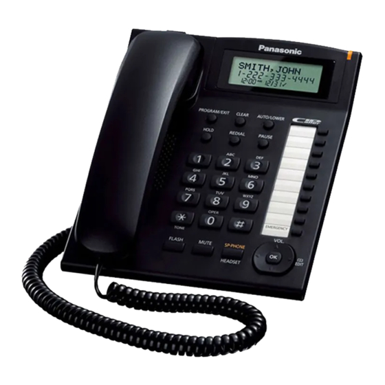
KX-TS880MXB
Service manual
Panasonic KX-TS880MXB Service Manual
Hide thumbs
1
2
Table Of Contents
3
4
5
6
7
8
9
10
11
12
13
14
15
16
17
18
19
20
21
22
23
24
25
26
27
28
29
30
31
32
33
34
35
36
37
38
39
40
41
42
43
44
page
of
44
Go
/
44
Contents
Table of Contents
Troubleshooting
Bookmarks
Table of Contents
Table of Contents
Safety Precautions
For Service Technicians
Warning
Battery Caution
About Lead Free Solder (Pbf: Pb Free)
Discarding of P. C. Board
Specifications
Technical Descriptions
Block Diagram
Circuit Operation
Location of Controls and Components
Installation Instructions
Operating Instructions
For Service Hint
Troubleshooting Guide
Service Hints
Pulse Dialing Problems
Tone Dialing Problems
No Ringing Sound When Ring Signal Is Input
Disassembly and Assembly Instructions
Disassembly Instructions
Assembly Instruction
Miscellaneous
IC Block Diagram
How to Replace the Flat Package
Terminal Guide of the Ics, Transistors and Diodes
Schematic Diagram
For Schematic Diagram
Schematic Diagram (Main)
Schematic Diagram (Operation)
Printed Circuit Board
Circuit Board (Main)
Circuit Board (Operation)
Exploded View and Replacement Parts List
Cabinet and Electrical Parts
Accessories
Replacement Part List
Advertisement
Quick Links
1
Operating Instructions
Download this manual
Caller ID Compatible
Telephone Equipment
KX-TS880MXB
Model No.
KX-TS880MXW
Integrated Telephone System
B: Black Version
W: White Version
(for Middle East and Asia)
© Panasonic System Networks Co., Ltd. 2010
Unauthorized copying and distribution is a violation
of law.
ORDER NO. KM41010286CE
Table of
Contents
Previous
Page
Next
Page
1
2
3
4
5
Advertisement
Table of Contents
Need help?
Do you have a question about the KX-TS880MXB and is the answer not in the manual?
Ask a question
Questions and answers
Related Manuals for Panasonic KX-TS880MXB
Telephone panasonic KX-TS840MX Specifications
Integrated telephone system (2 pages)
Telephone panasonic KX-TS820 Specifications
Integrated telephone system (2 pages)
Telephone Panasonic KX-TS880EX Operating Instructions Manual
Integrated telephone system (36 pages)
Telephone Panasonic KX-TS840B Service Manual
Integrated telephone system (13 pages)
Telephone Panasonic KX-TS880MXW Service Manual
(44 pages)
Telephone Panasonic KX-TS820MXB Service Manual
Telephone equipment (29 pages)
Telephone Panasonic KX-TS800 Operating Instructions Manual
Integrated telephone system (43 pages)
Telephone Panasonic KX-TS620B Service Manual
(14 pages)
Telephone Panasonic KX-TS3282B Service Manual
Integrated telephone system black version (84 pages)
Telephone Panasonic KX-TSC7 User Manual
Panasonic kx-tsc7: user guide (31 pages)
Telephone Panasonic KX-TSC11EX Operation Manual
Operation manual (greek) (6 pages)
Telephone PANASONIC KX-TS620EX Operating Instructions Manual
Telephone answering system (60 pages)
Telephone Panasonic KX-TS3MXB Service Manual
Telephone equipment (25 pages)
Telephone Panasonic KX-TSC11MXB Service Manual
Integrated telephone system (49 pages)
Telephone Panasonic KX-TSC11CB Service Manual
Integrated telephone system (27 pages)
Telephone Panasonic KX-TS550MEB Service Manual
(31 pages)
This manual is also suitable for:
Kx-ts880mxw
Table of Contents
Save PDF
Print
Rename the bookmark
Delete bookmark?
Delete from my manuals?
Login
Sign In
OR
Sign in with Facebook
Sign in with Google
Upload manual
Upload from disk
Upload from URL


Need help?
Do you have a question about the KX-TS880MXB and is the answer not in the manual?
Questions and answers