Table of Contents
Advertisement
Quick Links
Installation Instructions for Licensed Electricians, Plumbers,
and Spa Technicians
All components are intended to be installed and tested by a licensed electrician who is experienced in spas
and hot tubs. A properly installed GFCI and grounding must be installed with any system. Installation
must be permitted and inspected prior to use.
Any sales or technical advice provided on the Spaguts.com website or by Spaguts.com staff shall not be
construed to authorize or suggest anything but professional installation.
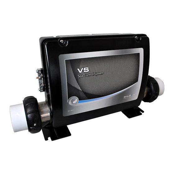
Balboa brand VS501Z Spa Controller Kit
Parts Content:
(1) Balboa brand VS501Z Spa Controller w/ M7 5.5KW Flo-Thru Heater, P/N G5152
(1) Topside Panel, VL200 Model w/ 7ft cable and 8-wire phone-type connector (Note that a topside substitution may be provided)
(1) Topside Overlay, P/N 11095 (Overlay may be pre-installed on topside panel)
(1) Topside Adapter Plate, P/N 11718
(2) Heater Split Nuts, 2 inch, P/N 40-350-5421 (installed on each end of heater)
(2) Heater Tailpieces, 2 inch, P/N 25-350-1052 (installed on each end of heater)
(2) Heater O-Ring Gaskets, 2 inch, P/N 25-350-4030 (installed on each end of heater)
(1) System Wiring Diagram, Labeled VS501Z – PN G5152 (attached to inside controller cover)
(1) Double-Sided Operation Guide with Diagnostic Messages, 500Z Series, P/N 40789
(1) Installation Instructions, P/N 73-200-8501
(1) Light Harness, 2-Prong Amp Plug, Light Socket, 8ft Cable
(1) Light Bulb, Clear, 12V 12W
(1) Pump Cord, 4ft, 4-wire, 14 AWG, w/ 4-Prong Amp Plug, P/N 15-150-3060
(2) Pump Cord, 4ft, 3-wire, 14 AWG, w/ 4-Prong Amp Plug, P/N 15-150-0024
Plumbing up the system:
This system will work if the pump draws or discharges water through the heater. Minimum water flow required is 25 GPM. Minimum
plumbing size required is 1.5 inch. This system is equipped with M7 Technology (no pressure switch). There are dual sensors installed
on the heater to measure the water temperature flowing through the heater. No need to mount any sensors or flow switches. The heater has
standard 2.0 inch plumbing fittings. If the spa plumbing is 1.5 inch, use reducers to connect to the heater 2.0 inch heater tailpieces. If re-
plumbing is necessary, use PVC Glue with primer to connect the plumbing. When installing an In-Line Filter System, either install it
before the heat pump and controller or after the heat pump and controller. Never install the filter system in between the heat pump and
controller. Make sure to create a water flow bypass plumbing around the filter for sufficient water flow. For systems installed near or
above the water level, and more than 5 feet from the tub, install the In-Line Filter System after the heat pump and controller with a water
flow bypass plumbing. A water flow bypass plumbing allows half the water to go through the filter and half the water to go around the
filter. This way water flow is not restricted. We recommend NSF rated flexible PVC for simpler connections. Go to this link for more
info: http://www.spaguts.com/Product.aspx?ID=42.
Wiring Instructions:
*110V Power Supply, 60Hz
*Minimum 20A Power Supply is required. Use Copper Conductors Only. See wiring diagram for more information.
Please note that this Installation requires 3 dedicated wire connections to the power terminal block (TB1) on the Circuit Board. These
include Line 1, Neutral and Ground. Connect Hot wire to Line 1 terminal. Connect Neutral wire to Neutral terminal. If a dedicated
Neutral wire is not connected, the heater will never come on and/or the system will not operate properly. For 110V operation, add a
jumper wire from terminal J11 to terminal J32 (SEE WIRING DIAGRAM FOR VERIFICATION). If this jumper wire is not installed,
Installation P/N 73-200-8501, Rev. B, 12/09/2020
Page 1 of 4
Advertisement
Table of Contents

Related Manuals for Balboa VS501Z


Summary of Contents for Balboa VS501Z
- Page 1 (2) Heater Tailpieces, 2 inch, P/N 25-350-1052 (installed on each end of heater) (2) Heater O-Ring Gaskets, 2 inch, P/N 25-350-4030 (installed on each end of heater) (1) System Wiring Diagram, Labeled VS501Z – PN G5152 (attached to inside controller cover) (1) Double-Sided Operation Guide with Diagnostic Messages, 500Z Series, P/N 40789...
- Page 2 the heater circuit will not activate. Note that this jumper wire may have already been installed at the factory. Lastly, connect Ground to the Grounding Bar located on the outside of the controller box. Run the Ground Wire through a hole that is labeled Green Ground located from the inside of the controller box.
- Page 3 Field Configuration. Topside Panel Installation: A hole cut out of 3.75 inch x 1.0 inch is required for the Balboa VL200 Model Topside Panel. A topside cover plate (included) may be used if the existing hole cut out is larger than the new topside panel. Clean the surface area before installation of the new topside panel.
- Page 4 Balancing water means establishing a balance among pH, total alkalinity and total hardness. Water that is unbalanced can corrode the spa and its support equipment or leave deposits of minerals. Properly balanced water is essential to allow the sanitizing chemical(s) to work effectively.
Need help?
Do you have a question about the VS501Z and is the answer not in the manual?
Questions and answers