Table of Contents
Advertisement
Quick Links
Specifications
Power Source :
Power Consumption :
Aerial Impedance :
Receiving System :
Receiving Channels :
VHF
UHF
CATV
Intermediate Frequency :
Video
Sound
AC AUTO 110-240V, 50/60 Hz
75Ω unbalanced
Coaxial type
17 Systems
1-11 PAL B (Australia & N.Zealand)
1-12 PAL/SECAM D
1-12 NTSC M JAPAN
2-12 PAL/SECAM B, G
2-13 NTSC M U.S.A.
21-69 PAL G I/SECAM B, G, K1
28-69 PAL G (Australia)
13-56 PAL D
13-52 NTSC M JAPAN
14-69 NTSC NTSC M U.S.A.
S1-S41 (Hyper)
38.0 MHz
31.5 MHz (D, K, K1)
32 MHz (I)
32.5 MHz (B, G)
33.5 MHz (M)
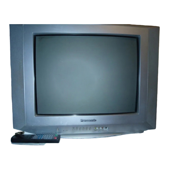
TC-21Z99M
GP31 Chassis
Colour
88W
Video / Terminals :
RAV In
Monitor Out
High Voltage :
Picture Tube :
Audio Output :
Dimensions :
Mass :
Specifications are subject to change without notice.
Mass and dimensions shown are approximate.
ORDER NO. PMI-T0705-03
Colour Television
33.75 MHz (SECAM)
Audio In Approx. 400mVrms
Video Out 1 Vp-p 75Ω
Audio Out Approx. 400mVrms
at zero beam current
Measured diagonally,
© 2005 Matsushita Electric Industrial Co., Ltd. All
rights
reserved.
Unauthorized
distribution is a violation of law.
33.57 MHz (PAL)
33.6 MHz (SECAM)
34.42 MHz (NTSC)
AV1, 2
Video In 1 Vp-p 75Ω
27.5kV±1.5
A51KQK99X06
51cm (21 inches)
90° deflection
16W
Height : 464.75 mm
Width : 612 mm
Depth : 476.3 mm
21.5 kg (Net Wt.)
copying
and
Advertisement
Table of Contents

Related Manuals for Panasonic TC-21Z99M


Summary of Contents for Panasonic TC-21Z99M
- Page 1 ORDER NO. PMI-T0705-03 Colour Television TC-21Z99M GP31 Chassis Specifications Power Source : AC AUTO 110-240V, 50/60 Hz Colour 33.57 MHz (PAL) Power Consumption : 33.6 MHz (SECAM) Aerial Impedance : 75Ω unbalanced 33.75 MHz (SECAM) Coaxial type 34.42 MHz (NTSC)
-
Page 2: Table Of Contents
TC-21Z99M CONTENTS Page Page 1 Safety Precautions 2.7. PAL Colour Output Level Adjustment 1.1. General Guide Lines 2.8. CRT VRS Adjustment 1.2. Leakage Current Cold Check 2.9. CRT Cut Off Adjustment 1.3. Leakage Current Hot Check (Fig. 1) 2.10. Purity and Convergen Adjustment 1.4. -
Page 3: Safety Precautions
TC-21Z99M 1 Safety Precautions 1.1. General Guide Lines 1. It is advisable to insert an isolation transformer in the AC supply before servicing this hot chassis. 2. When servicing, observe the original lead dress, especially the lead dress in the high voltage circuits. If a short circuit is found, replace all parts which have been overheated or damaged by the short circuit. -
Page 4: Gp31 Chassis Block Diagram
TC-21Z99M 1.5. GP31 Chassis Block Diagram... -
Page 5: Service Hints
TC-21Z99M 2 Service Hints 2.1. Service Position for E-Board 1. Remove the back cover. 2. Stand the TV set as shown in Fig. 2. 3. Remove the A-Board from the TV set by pulling the main board out as shown in Figure 2. -
Page 6: B Voltage Confirmation
TC-21Z99M 2.3. +B Voltage Confirmation 2.5. RF AGC Adjustment Item / preparation Item / preparation 1. Operate the TV set. 1. Receive a colour bar signal at an RF level of 69 ± 1-2 dBU with 75Ω loaded. 2. Set control as follows : 2. -
Page 7: Pal Colour Output Level Adjustment
TC-21Z99M 2.7. PAL Colour Output Level Adjustment 1. Receive the PAL B/G studio colour bar pattern and adjust local frequency at the best tuned position. 2. Pic Menu: Dynamic Normal, Confirm Contrast - 100 DAC, Sub Contrast - 21 dac. -
Page 8: Crt Vrs Adjustment
TC-21Z99M 2.8. CRT VRS Adjustment Adjustment of CRT VRS 1. Preparation a. Set DY to CRT not to tilt up and down left and right deflection. b. Set CY to CRT and set CY magnet primarily (Fig. 1) Purity magnet : Set purity magnet that 2 magnets are (TOP POSITION) VRS magnet : Set purity magnet 2 magnets are (HORIZONTAL POSITION) 2. - Page 9 TC-21Z99M Fig. 10 Fig. 11 Notes: 1. Wedge A, B and C should be inserted following the sequence of 1, 2 and 3 shown in Fig. 11. 2. The wedges should be set 120° apart from each other. 3. Be certain that three wedges are firmly fixed and the Deflection Yoke is tightly clamped in place.
-
Page 10: Crt Cut Off Adjustment
TC-21Z99M 2.9. CRT Cut Off Adjustment Preparation: 1. Connect the oscilloscope probe to TPL5. 2. Screen VR min. 3. Set the data Sub Bright, Bright. 4. In service Mode at “Bright” dac press [5] in factory mode to enter vertical line and adjust by volume down or up button. -
Page 11: White Balance Adjustment
TC-21Z99M Convergence 1. Apply a crosshatch pattern signal and Normalize Contrast 4. Adjust Red and Blue with Green line at centre of the screen control to the maximum positions. by rotating (RB)-G static convergence magnetic rings. 2. Adjust Brightness until the grey position of the crosshatch 5. -
Page 12: Conductor Views
TC-21Z99M 3 Conductor Views... -
Page 13: Schematic Diagram
TC-21Z99M 4 Schematic Diagram... - Page 14 TC-21Z99M...
-
Page 15: A Board
TC-21Z99M 4.1. A Board 4.1.1. A Board (1/5) <1A> <2A> <3A> <4A> <5A> <6A> <7A> <8A> <9A>... - Page 16 TC-21Z99M 4.1.2. A Board (2/5) <1A> <1B> <2B> <2A> <3B> <3A> <4A> <4B> <5A> <5B> <6A> <6B> <7B> <7A> <8B> <8A> <9A> <9B>...
- Page 17 TC-21Z99M 4.1.3. A Board (3/5) <1B> <1C> <2C> <2B> <3C> <3B> <4C> <5C> <4B> <6C> <5B> <6B> <7C> <7B> <8B> <8C> <9B> <9C>...
- Page 18 TC-21Z99M 4.1.4. A Board (4/5) <1C> <1D> <2C> <2D> <3C> <3D> <4D> <4C> <5C> <6C> <5D> <6D> <7C> <7D> <8C> <9C>...
- Page 19 TC-21Z99M 4.1.5. A Board (5/5) <1D> <2D> <3D> <4D> <5D> <6D> <7D>...
-
Page 20: L Board
TC-21Z99M 4.2. L Board 4.2.1. L Board (1/3) <1A> <2A> <3A> <4A> <5A> <6A> <7A>... - Page 21 TC-21Z99M 4.2.2. L Board (2/3) <1A> <1B> <2A> <3A> <2B> <4A> <5A> <3B> <4B> <5B> <6A> <7A> <6B>...
- Page 22 TC-21Z99M 4.2.3. L Board (3/3) <1B> <2B> <3B> <4B> <5B> <6B>...
-
Page 23: Parts Locations
TC-21Z99M 5 Parts Locations... -
Page 24: Replacement Parts List
TC-21Z99M 6 Replacement Parts List... -
Page 25: Replacement Parts List
TC-21Z99M 6.1. Replacement Parts List Ref. Part No. Part Name & Description Remarks C2121 ECJ2VF1C104Z C 0.1F, Z, 16V Ref. Part No. Part Name & Description Remarks C2124 F2A1C100A180 E 10F,16V C2125 ECJ2VF1C105Z C 1F, Z, 16V A51KQK99X06 PICTURE TUBE ITC... - Page 26 TC-21Z99M Ref. Part No. Part Name & Description Remarks Ref. Part No. Part Name & Description Remarks C612 ECJ2VB1H472K C 4700PF, K, 50V D1151 B3AGA0000092 DIODE C613 ECJ2VB1H472K C 4700PF, K, 50V D120 MA2C85800E DIODE C614 ECQV1H104JL3 P 0.1F, J, 50V...
- Page 27 TC-21Z99M Ref. Part No. Part Name & Description Remarks Ref. Part No. Part Name & Description Remarks L182 TALV35VB6R8K PEAKING COIL R1020 ERJ6ENF8200V M 820 OHM, J, 1/10W L183 G0C5R6KA0030 PEAKING COIL R1021 ERJ6GEY0R00V M 0 OHM, J, 1/10W L184...
- Page 28 TC-21Z99M Ref. Part No. Part Name & Description Remarks Ref. Part No. Part Name & Description Remarks R3033 D0GD101JA017 F 100OHM, J, 1/10W R605 ERJ6GEYJ101V M 100OHM, J, 1/10W R3034 D0GD181JA017 F 180KOHM, J, 1/10W R606 ERJ6GEYJ101V M 100OHM, J, 1/10W...
- Page 29 TC-21Z99M Ref. Part No. Part Name & Description Remarks JS2132 ERJ6GEY0R00V M 0OHM, J, 1/10W JS2140 ERJ6GEY0R00V M 0OHM, J, 1/10W JS2141 ERJ6GEY0R00V M 0OHM, J, 1/10W JS3001 ERJ6GEY0R00V M 0OHM, J, 1/10W JS3129 ERJ6GEY0R00V M 0OHM, J, 1/10W JS3132...
Need help?
Do you have a question about the TC-21Z99M and is the answer not in the manual?
Questions and answers