
Related Manuals for Ring Engineering AM-1b


Summary of Contents for Ring Engineering AM-1b
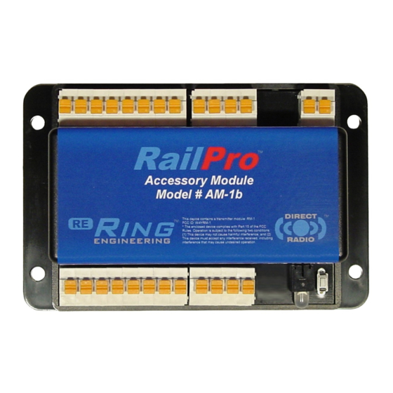
- Page 1 Model Railroad Accessory Module (AM-1b) User Manual Ring Engineering Inc. (219) 322-0279 www.RingEngineering.com Revision 2.01 Copyright © 2018 Ring Engineering Inc. All rights reserved.
-
Page 2: Table Of Contents
FCC Statement ..............12 Notification: Ring Engineering believes that our AM-1 module is compatible with most HO Scale turnouts. However, it is not practical for Ring Engineering to test our module with all available turnouts. Further, we cannot control the manufacturing or specification changes from other manufacturers. -
Page 3: Warnings
WARNING: This product is not recommended for persons under fourteen (14) years of age. WARNING: Only connect a Ring Engineering approved power supply to the proper power input connections. Maximum voltage is 16 Volts DC. A power supply with excessive voltage or improper voltage can cause a fire. You can... - Page 4 “Power In” terminals labeled ‘P1’ and ‘P2’ with 16-gauge wire. Only connect a Ring Engineering approved power supply to the proper power input connections such as the PWR-56. Maximum voltage is 16 Volts DC. A power supply with excessive voltage or improper voltage can cause a fire.
- Page 5 At this time you may also want to give this newly detected product a name and a password. See the password section for more information on passwords. You must select the proper type of switch before connecting any switches. Ring Engineering Inc...
- Page 6 Type 3 Snap 2 wire. Only one type of switch can be wired to an AM-1. See the section below for the type of switches you will be connecting. NOTE: Ring Engineering highly recommends using motor operated switches instead of snap type switches. Snap type switches can take 100 times the power needed to operate a switch compared to a motor operated switch.
- Page 7 A resistance measurement from the center tap to either of the two end wires should measure about half of the resistance as the resistance from one end wire to the other. Ring Engineering Inc...
- Page 8 The Activation Time adjustment sets the time the AM-1 will send power to the turnout to get the turnout to change positions. It is important that you adjust the Activation Time to only power the turnout just long enough to make the turnout move to a position dependably. Ring Engineering Inc...
-
Page 9: Passwords
AM-1 on your controlling device. You can give the AM-1 any name that you would like. Password It is recommended that you give your AM-1 a password. Please read the Password section for more information. Ring Engineering Inc... -
Page 10: Advanced Adjustments
R1 or R2 reference voltage terminals. The other side needs to be connected to the proper input as shown in table 4. The switches need to be of type ‘normally open,’ and close when the proper switch position is achieved. Ring Engineering Inc... -
Page 11: Status Indicator Light
Reference Signal for use with inputs IO1 – IO8 IO1 – IO8 Programmable Input or Output Pins (Turnout Feedback Inputs) O1 – O8 Output Pins. Connections for Turnouts. OP1 – OP4 + Voltage Source (Connected Power Supply Voltage) Ring Engineering Inc... -
Page 12: Warranty
If your Ring Engineering product is not covered by warranty, or has been damaged, an estimate of repair costs or replacement costs will be provided to you for approval prior to servicing or replacement.
Need help?
Do you have a question about the AM-1b and is the answer not in the manual?
Questions and answers