
Related Manuals for TPC Mirage 2.0 Hydraulic


Summary of Contents for TPC Mirage 2.0 Hydraulic
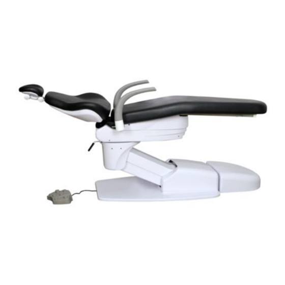
- Page 1 Mirage 2.0 Hydraulic Patient Chair Installation, Operation & User Manual 851 S. Lawson St. City Of Industry, CA 91748 P626-810-4337 Fax 626-810-4245 www.tpcdental.com...
-
Page 2: General Information
Table on Contents: Page GENERAL INFORMATION Installation and coordination Installing dental chair upholstery Overview of controls Calibrating Chair Motors CLEANING & DISINFECTING GUIDE Warranty TROUBLE SHOOTING GUIDE www.tpcdental.com... - Page 3 GENERAL INFORMATION The dental chair is marked with a product identification label including manufacture, serial number and date of manufacture. This label is located on the left side cover of the dental chair. The dental chair is marked with a This label is Risk Class symbol. located on the left side cover of the dental chair. The dental chair is marked with a main electrical grounding point symbol. This label is located on the base of the chair. www.tpcdental.com...
- Page 4 The dental chair is marked with a main electrical grounding point symbol. This label is located on the front left side of the dental chair steel base frame, under the plastic cover. The dental chair is marked with a fuse label symbol. This label is located under the pump cover on The fuse is a 10-amp Fuse,5x20mm the front left side of the chair frame. Transportation / Storage Information • Do not store the dental chair in temperatures exceeding 130 degrees. • Do not store the dental chair on its side. Always store upright on pallet. • Do not stack more than 5 packaged chairs at a time on top of each other. • Use approved pallet jack or forklift to move the dental chair. • Do not attempt to move stacked dental chairs. • Only store the dental chair in dry cool place. www.tpcdental.com...
- Page 5 Dental Chair Installation Instructions 1. Remove the plastic covers from the base of the dental chair. Slide the back cover straight back to remove it from the chair base. 2. Remove the 4 shipping bolts that secure the chair to the pallet. Two are up front and two are towards the back of the chair. www.tpcdental.com...
- Page 6 Remove the lift handles from the pallet. Install on the threaded hub on each side of the chair. These are going to be used as a lift point. Do-not use the chair armrest as lift points. 4. After the chair is placed in the installation location, Install the leveling lugs in the holes that were used to secure the chair to the pallet. These will be used to level the chair base in the event the floor is not level. www.tpcdental.com...
- Page 7 5. Remove the lift handles from the backrest mount by removing the two 14mm bolts. 6. Secure the backrest support to mounting hub using the (4) 6mm Allen bolts. You don’t need to remove the plastic cover. Gently slide the backrest hub between the plate and the plastic cover. www.tpcdental.com...
- Page 8 Installing Dental Chair Upholstery 1. Open the bolt package included in your upholstery box. 2. Locate the nuts and bolts shown in figure 1. 3. Attach the nuts to the bolts and place them in the backrest frame as shown in figure 2. Adjust the nut so that the head of the bolt and the back of the nut can slide up and down with little resistance in the back rest frame. 4. Once the space is adjusted remove the bolts with the nuts still attached and try to keep the spacing the same. 5. Place the bolts into the backrest as shown in figure 3 6. Slide the upholstery into the backrest bracket. Press gently on the backrest upholstery side so that all four bolts align properly. Once aligned apply pressure to the top of the upholstery and lock it into place. Figure 4 Figure 1 Figure 3 Figure 4 Figure 2 www.tpcdental.com...
- Page 9 7. Take the seat cushion out and place it upholstery side down. 8. Locate the rivet insert holes to mount the seat cushion hardware. 9. Use the Allen screws, lock washers and washers shown in figure 1 to attach the s-bracket shown in figure 2 to the upholstery 10. Mount the s bracket as shown in figure 3. 11. Attach the two supplied Allen screws to the chair seat cushion frame shown in figure 3. Figure 1 Figure 2 Figure 3 Correct: Notice that the S-bracket is flush with the end of the upholstery. Incorrect: Mounting the S-bracket this way will damage the upholstery frame. Damage will occur. Notice that the bracket is hanging over the upholstery. www.tpcdental.com...
- Page 10 12. Insert the chair seat cushion into the seat pan bracket notch shown in figure 1. You will notice that the seat pan is notched so that the bracket can slide into place and not move from left to right. 13. locate the Allen screws, lock washer and washers shown in figure 2 14. Once the bracket is securely in place you may fasten the toe of the upholstery to the frame as shown in figure 3. 15. Attach the headrest upholstery to the headrest stem as shown in figure 4. Be sure to use the counter sunken Phillip head screws shown in figure 3. Don’t over tighten the screws. Figure 1.1 Figure 1 Figure 2 Figure 3 www.tpcdental.com...
- Page 11 1. Place the plastic cover over the headrest cushion. 2. Attach the headrest cushion to the headrest stem using 3 (2.5MM) Allen screws. Bag (E) www.tpcdental.com...
- Page 12 Overview of foot control operations 1. Seat Height Adjustments To raise, press down on upper area of the foot control. To lower, press down on the lower area of the foot control. 2. Backrest Adjustments To raise, press down on right side of the foot control. To recline, press down on left side of foot control. 3. Preset Operation Manually move the chair to the desired position. Press and hold the pre-set switch (#1, or #2) on the foot control to program. After 5 seconds you will hear a confirmation beep. 4. Automatic Return Momentarily press 0 switch on foot control to activate chair to return to normal position. 5. LP Last position By pressing the (LP) last position button the chair backrest will travel to the last position. Chair Base up Preset 2 Preset 1...
- Page 13 Overview of optional touchpad controls Chair Base up Chair back down Chair Back UP Cuspidor Bowl Cuspidor Cup Fill Rinse Chair Base down Preset 1,2 and 3 Last Position Auto Return Light On / Off Light On / Off www.tpcdental.com...
- Page 14 Safety Plate A safety plate is provided under the cantilever cover to stop motion of chair when object is accidentally caught underneath. Armrest Rotation Either armrest can be rotated outward by grasping the end portion of armrest, pulling upward and turning. Headrest Adjustments Height of headrest can be adjusted simply by pulling headrest up or down due to friction mount incorporated in backrest. Angle of articulating headrest can be changed by releasing slide bar on headrest stem...
- Page 15 Motion Limit Controls Function The Mirage Hydraulic Patient Chair does not use conventional mechanical or mercury limit switches. Motion of the chair base and backrest move variable resistances (potentiometers) making it possible for the control circuitry to continuously know the exact position of the base and backrest, not only when they hit the end of their travel.
- Page 16 Main PCB Board Auto Limit Function: The Mirage 2.0 dental chair PCB can perform an auto limit function. To perform this procedure slide “S6” to the “ON” position by sliding it down. Verify there are no obstructions around the dental chair. This includes the delivery unit arms and operatory light. Press and hold “S2” (Back UP) button. When this button is initially pressed the board will tone. Keep this button held in for 5 seconds. When you hear the second beep the chair will begin to move in its own. You may release the button when the chair begins to move. The chair will go through two complete cycles of movement. The first cycle is the maximum travel of the chair. The second cycle will deduct about 10% of the first measured movement from cycle 1. Once this procedure is complete the chair will sit in an exit position with the base down and the backrest up. The board will continue to beep when this procedure is complete. Slide “S6” to the off position. During this process if the chair short travels, this indicates that there is a problem reading the resistance of the potentiometers to the main PCB. Or the safety plate is being engaged. You will need to check the potentiometer set screws for the backrest and seat base and try the process again. You can disconnect the safety plate from the main PCB board during this process and re connect when complete if necessary. www.tpcdental.com...
-
Page 17: Wiring Schematic
Wiring schematic www.tpcdental.com... - Page 18 Operating Speed Controls Operating speeds are preset at factory but can be changed if desired. • TV1 = Base up flow control • TV2 = Base down Flow Control • TV3 = Back up flow control • TV4 = Back down flow control When adjusting the flow control valves counterclockwise turns will open / increase flow.
- Page 19 Main Power Switch and fuse location When the main power switch it illuminated the power is “ON”. If the switch is not illuminating and is in the UP position “On” Check the two 10 Amp fuses to the right of the switch. Disconnect the main power cord when checking the fuses. These fuses are 10Amp 250v 5X20mm glass fuses. Replace if necessary. If a fuse blows immediately, this indicates there is a short in the wiring. Contact a service technician or call TPC technical support. www.tpcdental.com...
- Page 20 Spray these solutions onto a cloth and wipe down the control surfaces. Be careful not to saturate the cloth. • Any action not recommended by the manufacture may cause risk of injury or shock! FOR ADDITIONAL INFORMATION CONTACT YOUR TPC DEALER www.tpcdental.com...
- Page 21 Mirage Model 4000 Troubleshooting Problem Cause Solution Dental Chair does not move No power Check power source up or down. Chair makes no Blown fuse Check fuse sound. Power switch off Check power switch Blown transformer Check transformer voltage 12vac Dental Chair will not move, Safety switch plate Check safety plate...
- Page 22 All of our products sold are guaranteed to be free from defects in workmanship and materials for a 1 year from date of purchase, unless otherwise stated. TPC will repair or replace any defective part at no charge. TPC will not be responsible for labor charges or shipping charges to / from the TPC facility.
Need help?
Do you have a question about the Mirage 2.0 Hydraulic and is the answer not in the manual?
Questions and answers