Table of Contents
Advertisement
Quick Links
GP22AE-1
Printed October 1, 2021
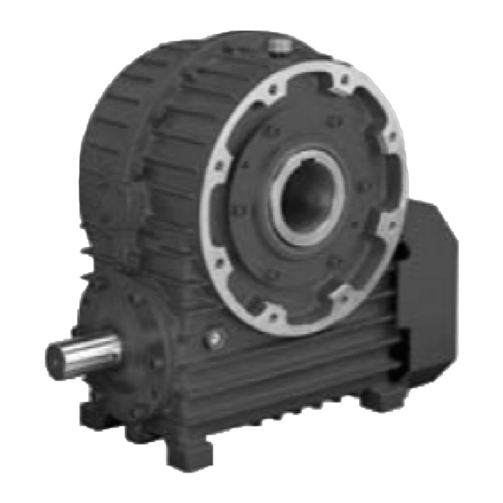
Tsubaki Troi Drive
TD series
Instruction Manual
Thank you for purchasing Worm power drive, Troi Drive, TD series.
Please read this instruction manual carefully and fully understand the reducer specifications for the
products installation and inspection. An experienced worker should handle the products carefully
with referring to instruction manual.
For model-to-order products, use this instruction manual with referring to drawings (specification
drawings or approval drawings) for your reducer. If you have any points unclear on this instruction
manual, please contact your supplier that you sourced the reducer, Tsubaki sales office, or
customer service.
Please ensure that this instruction manual is delivered to the end user who will use the reducer.
Carefully keep this instruction manual to be referred at any time in need.
TSUBAKIMOTO CHAIN CO.
Advertisement
Table of Contents

Related Manuals for Tsubaki TD Series

Summary of Contents for Tsubaki TD Series
- Page 1 For model-to-order products, use this instruction manual with referring to drawings (specification drawings or approval drawings) for your reducer. If you have any points unclear on this instruction manual, please contact your supplier that you sourced the reducer, Tsubaki sales office, or customer service.
-
Page 2: Table Of Contents
Contents Safety precautions ······························································································· P 3 1. When the gear box delivered, ············································································· P 5 1-1. What to be checked ·············································································· P 5 1-2. When inquiring ································································································ P 5 1-3. Models ············································································································ P 6 2. Transportation ································································································ P10 3. Installation ····································································································· P10 3-1. -
Page 3: Safety Precautions
Safety precautions In order to use this reducer safely, always be aware of the followings. ● An experienced worker should handle the reducer carefully. The content listed in this instruction manual must be carefully read and fully understood before using the reducer. ●... - Page 4 CAUTION (Overall) ● Do not use the reducer outside of the specifications listed on the nameplate or the specifications in the manufacturing specification document. Otherwise, there is a risk of injury and damage to equipment. ● Do not insert fingers or objects into the openings on the reducer. Otherwise, there is a risk of electric shock, injury, and damage to equipment.
-
Page 5: What To Be Checked
□ 1 When delivered 1-1. What to be checked at first Check the following points upon receipt of your reducer. If it has any problem, please contact the supplier where the reducer was sourced or Tsubakimoto Chain Co. customer service. CAUTION ●... - Page 6 1-3-1. Models, TD series Single reduction (1) Solid output shaft type Product Size Output shaft Nominal Mounting position Shaft arrangement series reduction ratio S: Solid shaft T: T type Refer to page 8 10: 1/10 B: B type 20: 1/20...
- Page 7 Double reduction (1) Solid output shaft type Product Size Output shaft Nominal Input shaft position Shaft arrangement series S: Solid shaft reduction ratio B: B type Refer to page 9. 100: 1/100 V: V type 150: 1/150 200: 1/200 250: 1/250 300: 1/300 450: 1/450 600: 1/600...
- Page 8 1-3-2. Shaft arrangements Single reduction (1) Solid output shaft type (S) (common to all sizes) type T type VLUD type VRUD (2) Hollow output shaft type (H) type BDF (TD225 to TD315) BRF (TD125 to TD200) BLF (TD125 to TD200) T...
- Page 9 Double reduction (1) Solid output shaft type (S) (common to all sizes) type B L-R B L-LR T type B R-LR B R-L V L-RU V L-RD V L-RUD type V R-LU V R-LD V R-LUD (2) Hollow output shaft type (H) B L-RF (TD125 to TD200) B L-DF (TD225 to TD315) type...
-
Page 10: Transportation
Bottom ↓ Bottom ↓ - If the installation is not as standard and made-to-order products, refer to the outline drawing or contact Tsubaki representative for the volume and type of lubrication. - Install on firm and flat installation surface that has enough strength and the installation mounting flatness should be within ±1°. -
Page 11: Hollow Output Shaft Type
Recommended bolts size and length for mounting Reducer size Recommended bolts M16 x 55 M20 x 60 M20 x 70 M24 x 80 M24 x 80 M30 x 100 M30 x 100 M30 x 110 - Avoid the deformation while installing reducer. 3-2. - Page 12 2. Removal procedures Lift the reducer using the lifting bolts. Loosen the end plate bolt which fixes (axial direction) the reducer to the driven shaft. Remove any attachments on the tip of the torque arm, which stops the shaft from rotating, so that it moves freely. (4) Remove the hollow output shaft from the driven shaft so as to prevent the application of excessive force between it and the housing.
-
Page 13: Connection
Do not change the brand of lubrication oil. Please contact to supplier where the product was purchased or contact to Tsubaki. For Daphne Alpha Oil TE, please contact to supplier where the product was purchased or contact to Tsubaki. - Page 14 40 to 50°C before draining the oil. • Tsubaki recommends flushing the inside of the housing with the new oil when replacing the oil. Note) Do not mix the oil with other brands.
- Page 15 Step Greasing procedures Add grease while the machine is all stopped and not in the operation. Greasing by the grease gun through grease port or grease nipple that located on the top of the housing. Use only the recommended grease. Note) Do not apply over grease.
-
Page 16: Operation
□ 6 Operation WARNING (Operation) ● During operation, do not get near or touch any rotating bodies (shafts or other parts). Otherwise, there is a risk of being caught in those parts resulting in injury. CAUTION (Operation) ● Do not insert your hand in the fan cover. Otherwise, there is a risk of being caught in those parts resulting in injury. ●... -
Page 17: Maintenance
□ 7 Maintenance WARNING ● In maintenance and inspection during operation, do not touch any rotating bodies (shafts or other parts). Otherwise, there is a risk of being caught in those parts resulting in accident. ● When entering the inside of the product to inspect it while stopped, first confirm that the rotation of the motor and the driven machine has stopped, and sufficiently cool the inside of the product, and then you must work while ventilating the interior. -
Page 18: Disassemble/Assemble
Oil seal and filter replacement procedures Replace the oil seals and filters attached to the various covers such as the housing, input seal support, output seal support, output bearing support, and the motor flange with the following procedure. Check the model and dimensions in the catalog and instruction manual to confirm that the oil seals and filters to replace are correct. -
Page 19: Troubleshooting
□ 9 Troubleshooting If a problem occurs with the reducer, refer to the table below to troubleshoot the problem. Problem Possible cause Action Overload operation Check and apply the correct load. Abnormal Insufficient or too much lubricant Fill with the appropriate volume. temperature rise Oil contamination or wrong oil Replaced with new and correct oil. - Page 20 < Major parts table> For consumables by size (bearings/oil seals), see the parts lists. Part name Part name Housing Worm shaft Fan cover Worm wheel Input shaft bearing Output shaft Input shaft bearing Input seal support Output shaft bearing Input bearing support I Input shaft oil seal Input bearing support III Output shaft oil seal...
-
Page 21: Parts Lists
Note) Both the load-side and fan-side input shaft oil seals are acrylic rubber. (TD100 & TD125 are nitrile rubber) - The output shaft oil seals are nitrile rubber. Figures in ( ) are for double shaft types. Made to order, and not available in general market. Contact Tsubaki representative for more information. -
Page 22: Storage
13-2. Warranty coverage During the limited warranty period, a failure in a Tsubaki product installed, used, and maintained according to the catalog, instruction manual, or other appropriate documents can be returned to Tsubaki for replacement or repair free of charge. - Page 23 (11) The product reaching the end of its normal service life according to the operating conditions. (12) Loss or damage not liable to the Seller. 13-4. Dispatching of Tsubaki engineers Service expenses such as those incurred when dispatching engineers to perform an investigation, adjustment, or trial operation of a Tsubaki product will be charged separately.
- Page 24 1-1, Kohtari-Kuresumi, Nagaokakyo TSUBAKIMOTO CHAIN CO. Kyoto 617- 0833 Japan Website: https://tsubakimoto.com/ Global Associated Partners: U.S. Tsubaki Power Transmission, LLC Tsubakimoto Singapore Pte. Ltd. Tsubakimoto Europe B.V. https://www.ustsubaki.com/ https://tsubaki.sg/ https://tsubaki.eu/ Tsubaki of Canada Limited Taiwan Tsubakimoto Co. Tsubakimoto U.K. Ltd.
Need help?
Do you have a question about the TD Series and is the answer not in the manual?
Questions and answers