Table of Contents
Advertisement
Quick Links
Advertisement
Table of Contents

Subscribe to Our Youtube Channel
Related Manuals for Bluetechnix Argos 3D P310


Summary of Contents for Bluetechnix Argos 3D P310
- Page 1 Argos 3D - P310 Hardware User Manual Version 1.3...
- Page 2 This document is protected by copyright. All rights reserved. No part of this document may be reproduced or transmitted for any purpose in any form or by any means, electronically or mechanically, without expressly written permission by Bluetechnix GmbH. Windows is a registered trademark of Microsoft.
-
Page 3: Table Of Contents
RS232/RS485 (e) ......................14 4.3.6 CAN-Bus (f) ........................15 4.3.7 Modulation Interface (LVDS) (g) ..................15 4.3.8 DIP-Switch (h) ........................16 4.3.9 Trigger and RS232 (i) ....................... 16 4.3.10 Power Connector (j) ......................16 4.3.11 I2C (c) ..........................17 © Bluetechnix 2014... - Page 4 Support ............................21 7.1.1 General Support ....................... 21 Software Packages ......................... 21 Related Products ........................21 Product History ..........................22 Version Information ......................... 22 8.1.1 Argos3D-P310 ......................... 22 Anomalies ..........................22 Document Revision History ....................22 Index ............................... 23 © Bluetechnix 2014...
- Page 5 Bluetechnix takes no liability for any damages and errors causing of the usage of this board. The user of this board is responsible by himself for the functionality of his application. He is allowed to use the board only if he has the qualification.
-
Page 6: General Information
Version 1.3 General Information This guide applies to the Argos 3D - P310 camera platform from Bluetechnix. Follow this guide chapter by chapter to set up and understand your product. If a section of this document only applies to certain camera parts, this is indicated at the beginning of the respective section. -
Page 7: Certification
Version 1.3 Certification 1.2.1 CE Declaration Bluetechnix hereby declares that this Argos 3D - P310 product is in compliance with the essential requirements and other relevant provisions of Directive 2004/108/EC. 1.2.2 FCC Declaration This device complies with part 15 of the FCC rules. Operation is subject to the following two conditions: (1) this device may not cause harmful interference, and (2) this device must accept any interference received, including interference that may cause undesired operation. -
Page 8: Safety Instructions
The electric supply must only be made via PELV circuits. The device must only be powered by a limited energy source (≤ 30V; ≤ 8A; ≤ 100VA). Disconnect power before connecting the unit. © Bluetechnix 2014 Page 8 | 23... -
Page 9: Overview
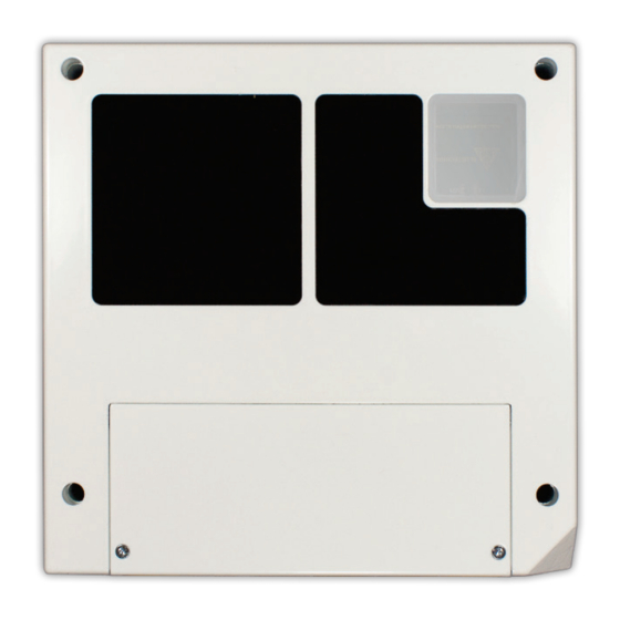
Last change: 14 October 2014 Version 1.3 Overview Components Figure 2-1 Argos3D-P310 components a. Case b. Viewing window for 3D sensor c. Viewing window for illumination module d. Interface board e. Interface cover © Bluetechnix 2014 Page 9 | 23... -
Page 10: Interfaces And Connectors
General purpose outputs, galvanic isolated d. General purpose inputs, galvanic isolated e. RS232/485 CAN-Bus g. Modulation Light Interface h. DIP-Switch Trigger, UART Power supply k. Boot loader mode button Reset button m. USB © Bluetechnix 2014 Page 10 | 23... -
Page 11: Hardware Installation
The case has four M3 holes that allows mounting the Argos3D-P310. 3.1.2 Mount Spacing The device is primarily intended for mounting on a wall or the ceiling. Leave enough space for air circulation. © Bluetechnix 2014 Page 11 | 23... -
Page 12: Board Description
All pins no. 1 of each connector are marked in the figures with a red arrow. The connector numbering always starts at this pin, continuing in this row, and going backwards at the opposite side. Markes Pin #1 Interface-Slot Marks Pin #1 Figure 4-1: Argos3D-P310 connector location © Bluetechnix 2014 Page 12 | 23... -
Page 13: Ethernet (A)
Table 4-2: General purpose output 3 & 4 connector description A solid state relay ASSR-3210 from Avago Technologies is used for each general purpose output. Voltage range: 18V to 30V. Current range: 0mA to 200mA. © Bluetechnix 2014 Page 13 | 23... -
Page 14: General Purpose Input 1 & 2 (D)
Table 4-4: GPIO Connector Description The interface mode can be selected with the DIP-Switch (see chapter 4.3.8). The RS232 interface is running in full duplex mode and the RS485 is running in half duplex mode. © Bluetechnix 2014 Page 14 | 23... -
Page 15: Can-Bus (F)
Table 4-6: Modulation Interface connector description The Modulation Interface provides the modulation signal for an external illumination module (differential LVDS). Note The cable length should not exceed 50cm. Caution Overvoltage on the Modulation Interface will destroy the Argos3D-P310. © Bluetechnix 2014 Page 15 | 23... -
Page 16: Dip-Switch (H)
This 3.5mm terminal connector allows plugging a cable entry plug like 691361100002 from Würth Elektronik. Compatible connectors from other manufacturers may be found as well. Signal Type Description Positive power supply Power ground Table 4-9: Power connector description © Bluetechnix 2014 Page 16 | 23... -
Page 17: I2C (C)
For further information about the factory default reset function see Software User Manual of the Argos3D- P310. 4.3.14 USB (m) This USB micro connector can be directly connected to a host computer. For further information about the USB function see Software User Manual of the Argos3D-P310. © Bluetechnix 2014 Page 17 | 23... -
Page 18: Software
Getting Started Software Development Example To facilitate the integration of the Argos camera in your own application a getting started example will be available on our support site. Software and documentation https://support.bluetechnix.com © Bluetechnix 2014 Page 18 | 23... -
Page 19: Appendix
Trigger Input Threshold High High Table 6-1: Operating Conditions Note Refer to the anomaly list for anomalies regarding the operating conditions. Mechanical Outline All dimensions are given in mm. Mechanical outline of the ‘Bounding Box’: © Bluetechnix 2014 Page 19 | 23... - Page 20 User Manual - Argos 3D - P310 Last change: 14 October 2014 Version 1.3 Figure 6-1: Mechanical outline of the bounding box © Bluetechnix 2014 Page 20 | 23...
-
Page 21: Support
User Manual - Argos 3D - P310 Last change: 14 October 2014 Version 1.3 Support 7.1.1 General Support General support for products can be found at Bluetechnix’ support site Support Link https://support.bluetechnix.at/wiki/ Software Packages Software packages and software downloads are for registered customers only Software Package ... -
Page 22: Product History
2014 07 14 First preliminary of the document 2014 07 29 Input voltage of TRIGGER_IN pin corrected. 2014 10 10 Cable length specification added. Anomaly list updated. Version information updated. Table 8-3: Revision history © Bluetechnix 2014 Page 22 | 23... -
Page 23: Index
Declaration ..............7 RS232/RS485 Connector Description ..........14 Declaration ..............7 Signal naming Nomenclature ............12 Software ..............18 Support ............... 21 Interfaces Overview ..............10 Version Product History ............22 Mounting Holes ............11 © Bluetechnix 2014 Page 23 | 23...
Need help?
Do you have a question about the Argos 3D P310 and is the answer not in the manual?
Questions and answers