Table of Contents
Advertisement
Quick Links
Advertisement
Table of Contents

Related Manuals for Entek IRD 6687


Summary of Contents for Entek IRD 6687
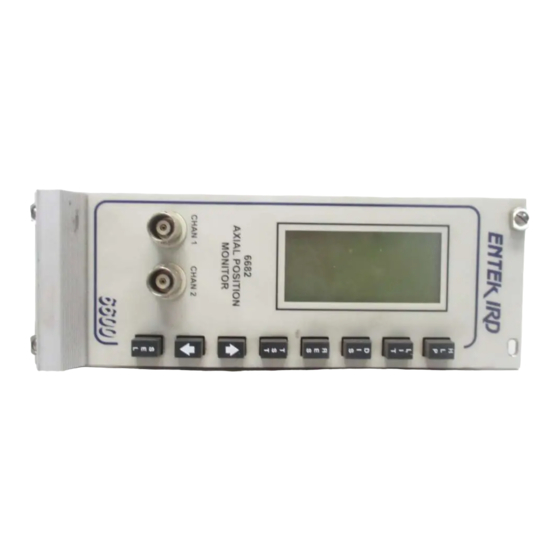
- Page 1 6687 Dual Channel Absoute/ Shell Expansion Monitor 500.0 6687 CASE EXPANSION MONITOR CHAN 1 CHAN 2 Your Guide to the 6687 Protection Monitor Entek IRD International Corporation P/N 45171...
- Page 2 Printed in the U.S.A. This Manual is supplied to the User under license, subject to recall by Entek IRD International Corporation at any time, and the Manual at all times remains the property of Entek IRD International Corporation. The information contained in this Manual is considered confidential.
-
Page 3: Table Of Contents
Setting the Display Scale and Zero Position......24 Entek IRD 6687 Protection Monitor... - Page 4 6687 Monitor Settings Worksheet ........
- Page 5 Entek IRD. If any sum is not paid by Customer when due, Entek IRD shall not be obligated to continue performance. If any amount is not paid when due, to the extent permitted by law a late fee of 1% per month (or any part thereof) shall be charged on past due amounts until paid.
- Page 6 90 days from performance. With respect to performance related in any way to the passage of time to the year 2000 and beyond, or the occurrence of a leap year, Entek IRD does not make any representation or warranty; Entek IRD has issued a Year 2000 readiness disclosure statement, which is available to Customer upon request.
- Page 7 Entek IRD as its attorney-in-fact to execute on Customer's behalf, any documents requested by Entek IRD which are necessary for attachment and perfection of its security interest. If Customer defaults, Entek IRD shall have all the rights of a secured creditor under the Uniform Commercial Code as enacted in Ohio.
- Page 8 (iii) disclose or permit access to the Software to any person or entity, except to the extent necessary to facilitate the permissible use thereof as set forth in (i) above. Entek IRD is under no obligation to furnish source code for any Software program.
- Page 9 Software. D. If Customer data comes into Entek IRD's possession, Entek IRD shall use the same level of care to maintain the confidentiality of that data which Entek IRD uses for its own confidential information.
- Page 10 Customer agrees that if the operation of the Entek IRD Software becomes, or Entek IRD believes is likely to become, the subject of such a claim, Customer will permit Entek IRD at its option and expense, either to secure the right for Customer to continue using the Entek IRD Software or to replace or modify it so that it becomes non-infringing.
- Page 11 Agreement or relationship. Waiver by Entek IRD of strict compliance with any one or more of these Terms and Conditions is not to be considered a continuing waiver or a waiver of any other term or condition.
- Page 12 Terms and Conditions Entek IRD 6600 Series Protection Monitors...
-
Page 13: Introduction
Danger alarm, or a “first out” Danger alarm message from another monitor, the 6687 stores this data in a separate memory area. A “first out alarm” is the first alarm in an interconnected series of monitors. This feature allows later analysis of the data leading up to the event that caused the Danger alarm. -
Page 14: Table Of Abbreviations
(signal detection) peak to peak (signal detection) root mean square (signal detection) °rot degrees of rotation revolutions per minute (frequency) µm micrometer Volt Volt AC Volt DC Entek IRD 6687 Protection Monitor... -
Page 15: Front Panel Description
Monitor Description Front Panel Description The 6687 front panel appears below. It consists of two bar graphs, showing the position of the two input channels relative to the full scale. Above the bar graph, the numeric display shows the actual value for the active input channel. The numeric display automatically switches between the two input channels every two seconds. -
Page 16: Inputs
Inputs The primary 6687 terminal connections are described below. For a complete listing of the inputs, see “Monitor Backplane” on page 8. Transducer input for each of the two input channels: Displacement sensor sensitivity specified in mV/mil, mV/mm, or mV/µm, adjustable in... -
Page 17: Customer Support
Display Backlight The backlight makes it easy to see the 6687 display, even in dim light. When the system is functioning properly and no signals are in alarm, the backlight is off. However, in case of an alarm or transducer failure, the 6687 automatically turns on the backlight to alert you. -
Page 18: Displaying Alternate Pages
6687 Monitor Displaying Alternate Pages The 6687 has two display pages. The first is the one pictured on page 3, and shows the two bar graphs. To display the second page, press and release the DIS button. There are three fields in the second display page. -
Page 19: Status Messages
Basic Operation Status Messages The 6687 can display a number of status messages that alert you to alarms or to problems with the transducers or monitoring system. This message appears when the transducer voltage signal goes out of the T X FAIL specified range. -
Page 20: Installation
6687 Monitor Installation This section contains information specific to installing the 6687. Refer to the manual on 6600 monitor installation for general monitor installation instructions. Monitor Backplane The following diagram shows the definitions for the 6687 backplane terminals. BACKPLANE DIAGRAM FOR A 6687 MONITOR... -
Page 21: Lvdt To Monitor Wiring
DIFFERENTIAL TRANSFORMER (LVDT) TO 6600 VIBRATION MONITOR Jumper = more positive reading on display when plunger is compressed Channel 1 Input Signal Input Signal S ignal Common +18 VDC Signal Common +18 VDC LINE NEUTRAL EARTH Entek IRD 6687 Protection Monitor... - Page 22 The 6691 power supply polarity must match the transducer. For example, if using an Entek IRD 15383, the 6691 must be configured to provide positive voltage. For more information on configuration of the power supply, refer to the manual on 6600 monitor power supplies and backplanes.
-
Page 23: Non-Contact Sensor To Monitor Wiring
The 6691 power supply polarity must match the transducer. For example, if using an Entek IRD 1900 non-contact sensor, the 6691 must be configured to provide negative voltage. The power supply is configured with jumpers on the power supply. For more information on configuration of the power supply, refer to the manual on 6600 monitor power supplies and backplanes. -
Page 24: Configuration
6687 Monitor Configuration This section describes how you configure the 6687. The 6600 Series protection monitors are easy to configure. All the controls to configure a 6600 monitor are on the front panel of the monitor. The 6687 has two levels of configuration: User menu –... - Page 25 If the current value does not change when you press the Arrow buttons, then the monitor is protected by the link security feature. Contact your Supervisor for assistance. For more information on the link security feature, contact Entek IRD Customer Support.
-
Page 26: User Menu Configuration
The controls to access the User menu and configure the 6687 monitor are all on the front panel of the monitor. See “Front Panel Description” on page 3 for a diagram of the front of the monitor. -
Page 27: User Menu Options
CLOCK HOURS ALARMS MINS ZRO TX1 SECS ZRO TX2 INHIBIT MONTH EXIT YEAR EXIT ALT1 HI DNG1 HI ALT1 LO DNG1 LO ALT2 HI DNG2 HI ALT2 LO DNG2 LO EXIT Described on page 17 Entek IRD 6687 Protection Monitor... -
Page 28: To Set The Date And Time
When done changing options, move the highlight to EXIT and press SEL to exit the EXIT menu. When you exit the submenu for CLOCK, the monitor displays the date and time for a few seconds before displaying the User menu. Entek IRD 6687 Protection Monitor... -
Page 29: Alarms Submenu
Note: With a model 15383 LVDT, you can choose to configure the jumpers on the LVDT to determine whether compressing the plunger means more positive or more negative on the display (upscale or downscale). See “LVDT to Monitor Wiring” on page 9. Entek IRD 6687 Protection Monitor... -
Page 30: Factory Menu Configuration
Relay operation Number of channels The controls to access the Factory menu and configure the 6687 monitor are all on the front panel of the monitor. See “Front Panel Description” on page 3 for a diagram of the front of the monitor. -
Page 31: Factory Menu Structure
20 page 18 LATCHED EXIT FS LO 2 FS HI EXIT DELAYS EXIT Described on GLOBAL page 21 Described on page 22 SECS Described on STARTUP page 22 SECS EXIT Described on page 24 Entek IRD 6687 Protection Monitor... -
Page 32: Comm's Submenu
Use the same scale factor as the MODBUS master. COMM’S EXIT Return to the Factory menu. The monitor remembers the current values for menu options, but does not write them to memory until you exit the Factory menu. Entek IRD 6687 Protection Monitor... -
Page 33: Ranges Submenu
For example, if you set TX1 SNS to 100 mV/mil and FS LO to –100 mV/mil, the monitor does not let you set FS HI above 100 mil. Entek IRD 6687 Protection Monitor... -
Page 34: Tx Ok Submenu
Factory menu. Note: The 6687 maintains a minimum of 1 volt and a maximum of 24 volts difference between the TX LO and the TX HI values, so it is not possible for the TX LO value to be greater than the TX HI value. - Page 35 Under normal (nonalarm) conditions, the relay closes the circuit between the common and the N/C (normally closed) terminals. Under alarm conditions, the relay changes state to close the circuit between the common and the N/O (normally open) terminals. Entek IRD 6687 Protection Monitor...
-
Page 36: Delays Submenu
This section guides you through setting the display scale and zero position for the monitor. The 6687 allows you to choose the display full scale high, full scale low, and zero position for your particular application. This example assumes that the full scale low position (cold position) for the case is at 0 mils. - Page 37 LO alarm levels below 0 to avoid setting off the LO alarms. If the 6687 is set to use both channels, repeat this process for the second channel. Entek IRD 6687 Protection Monitor...
-
Page 38: Testing Calibration And Relays
To obtain the voltage at FS HI, place a spacer between the case and the plunger of the LVTD. The spacer should be the same length as the maximum change in case expansion (1000 mils for this example). Entek IRD 6687 Protection Monitor... - Page 39 Transducers may be simulated directly at the backplane as shown or elsewhere. If this involves application via barriers, ensure that the barrier rating is not accidentally exceeded. Verify the DC source voltage with a DVM at the monitor terminal strip. Entek IRD 6687 Protection Monitor...
-
Page 40: Calibration And System Ok Relay Test
Increase the DC voltage input to the voltage at FS HI. Look at the 6687 front panel display, and note the digital value for channel 1. It should be the same as the FS HI setting ± 2.5% of full scale. -
Page 41: Alarm Relay Test
LO alarm setpoints go into alarm when the input value goes below the alarm level. Remember that the 6687 has both LO and HI alarms. You should test both sets of alarms for each channel if you are using them. - Page 42 Repeat this process to test the LO alarms for channel 1 (if used), and then the HI and LO alarms on channel 2. Remember that the HI alarms use the same alarm relays as the LO alarms. Entek IRD 6687 Protection Monitor...
-
Page 43: Specifications
Specifications Specifications The following are the technical specifications for the 6687. Inputs Transducer type 1 or 2 LVDTs or non-contact probes Input impedance Greater than 100k ohms at DC Transducer sensitivity 1.0 to 9999.9 mV/engineering unit, configured from front panel Voltage range Maximum applied voltage ±24 V, maximum usable input range... - Page 44 Transducer OK - transducer low and high bias voltage each channel Relays - failsafe or nonfailsafe, latching or nonlatching, time delays Channels - 1 or 2 input channels Display zeroing - each channel can be zeroed to show the desired display value Entek IRD 6687 Protection Monitor...
- Page 45 Storage: –4° F to +167° F (–20° C to +75° C) Relative humidity 0 to 95%, noncondensing Conformal coated circuit board and components Vibration Vibration applied in three mutually-perpendicular planes, 10–58 Hz at constant displacement of 0.15mm, 58–500 Hz at constant acceleration of 1.0 g Entek IRD 6687 Protection Monitor...
-
Page 46: 6687 Monitor Settings Worksheet
6687 Monitor 6687 Monitor Settings Worksheet This worksheet gives you a place to record the 6687 protection monitor settings. If you have to replace the monitor with a spare, this worksheet will allow you to configure the new monitor quickly and easily. We encourage you to copy these pages and fill in the values for future reference. - Page 47 –24.00 to 23.00 V TX HI 2 –23.00 to 24.00 V RELAYS submenu FAILSAFE AD, –D, A–, NO LATCHED YES, NO DELAYS submenu GLOBAL 0.0 to 30.0 sec STARTUP 0.0 to 30.0 sec CHANS 1, 2 Entek IRD 6687 Protection Monitor...
- Page 48 6687 Monitor Entek IRD 6687 Protection Monitor...
- Page 49 ALERT message 7 email 5 ALT1 HI menu option 17 hotline 5 ALT1 LO menu option 17 services 5 ALT2 HI menu option 17 ALT2 LO menu option 17 alternate display pages 6 applications 1 Entek IRD 6687 Protection Monitor...
- Page 50 9 Factory menu options LIT button 4, 5 CHANS 18 “LOCAL RELAY RESET” message 6 COMM’S 18 LVDT 9 RANGES 18 RELAYS 18 TX OK 18 menu structure Factory menu 19 User menu 15 Entek IRD 6687 Protection Monitor...
- Page 51 24 status messages 7, 22 “SYS FAIL” message 7 System OK relay, testing 28 RANGES menu option 18 table of abbreviations 2 technical specifications 31 Technical Support See Customer Support terminals diagram 8 Entek IRD 6687 Protection Monitor...
- Page 52 TX2 SNS menu option 21 UNITS 1 menu option 21 UNITS 2 menu option 21 Up Arrow button 4, 12 User menu ALARMS submenu 17 CLOCK submenu 16 configuring 14 description 12 displaying 14 options 15 structure 15 Entek IRD 6687 Protection Monitor...
Need help?
Do you have a question about the 6687 and is the answer not in the manual?
Questions and answers