Table of Contents
Advertisement
Advertisement
Chapters
Table of Contents

Related Manuals for Marsh PatrionPlus

Summary of Contents for Marsh PatrionPlus
- Page 1 Technical Manual Videojet Technologies Inc., Wood Dale, IL 60191 U.S.A.; Tel: (618) 234-1122; Tel: (800) 527-6275; Fax: (618) 234-1529. ©Videojet Technologies Inc. 2002. All Rights Reserved. “Marsh” is a registered trademark of Videojet Technologies Inc Printed in U.S.A. 29669...
- Page 2 Serial Numbers Write the serial numbers from your Marsh equipment in the appropriate spaces on this page. If you need to call Technical Support, they will ask for this information. Technical Support: — Telephone – U.S. and Canada: 800-851-3441 — Telephone – International: 618-234-9093 —...
- Page 3 Table of Contents Introduction (Rev AF) Specifications (Rev AF) Installation (Rev AF) Operation (Rev AG) Maintenance (Rev AF) Troubleshooting (Rev AF) Repair (Rev AF) Parts List (Rev AF) Appendix A (Rev AE) Appendix B (Rev AE) Appendix C (Rev AG) Glossary (Rev AE) Index...
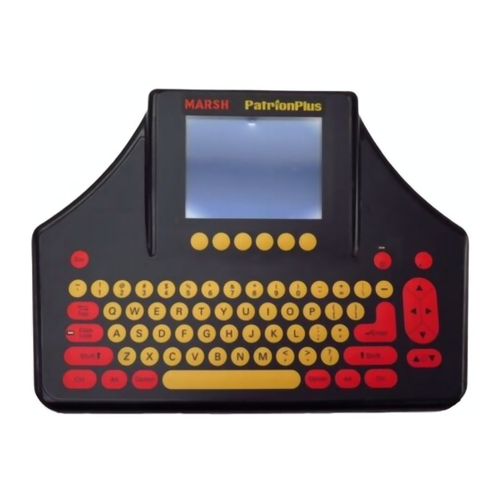
- Page 4 1-Introduction The Marsh PatrionPlus is a light weight controller with a tactile keypad and built-in LCD. It is capable of driving up to eight printheads on one production line. Using the dual tasking feature, the PatrionPlus can drive an additional eight printheads on a second production line.
- Page 5 Specifications 2-Specifications Table of Contents Component Overview . . . 2-1 Controller . . . 2-3 Certifications . . . 2-3 Weight . . . 2-3 Message Storage . . . 2-4 Electrical Requirements . . . 2-4 Mounting Options . . . 2-4 ML8 Emulation .
- Page 6 Specifications Conveyor Line Speeds . . . 2-24 Substrates . . . 2-24 Swing Arm Bracketry . . . 2-26 HR Slide Bracket . . . 2-27 15" Square Tube (Optional) . . . 2-27 Data Lines . . . 2-27 Printhead Power Supply .
- Page 7 Specifications Component Overview Following is a typical PatrionPlus system using VJ7, VJ16 and HR Series Printheads, ADS and Series 2000 Ink Systems, and all related components. Figure 2A: PatrionPlus System HR Series Printhead VJ Series Printhead Low Ink Alarm Beacon...
- Page 8 Specifications Figure 2B: PatrionPlus System Cable Routing HR Series Printhead VJ Series Printhead Photocell Printhead Shaft Photocell/Encoder Encoder Power Supply Splitter Box Printhead Power Cable Printhead Printhead Terminator Data Line Y-Cable Controller 29669/02012 Rev AF...
- Page 9 – CE Certified – FCC Part 15A – NEMA 12 - IP51 – CAN/CNA Std. C22.2 No. 950 To maintain CE/ETL approval, use only Marsh components with the PatrionPlus system. Failure to do so cancels CE/ETL approval. Weight 7 lb (3 kg)
- Page 10 – Mount in a NEMA Enclosure on a Flex Stand See “Controller Mounting Options” on page 2-14 for more details. ML8 Emulation Allows you to operate the PatrionPlus system using a Keyboard Input Device (KID) or any other RS-232 device. Software Features...
- Page 11 Specifications Messages Using a dual task key, you can create and store up to 3,000 messages. Maximum message length: 65" (165.1 cm) or 78 characters (at the default software settings 50 ft/min (15 m/min) line speed and character width 40) –...
- Page 12 Specifications VJ7 and VJ16 Series Fonts Note: Sample VJ fonts are actual size. Font widths may vary depending on character width chosen and line speed. VJ Series Fonts Height Printhead Font Sample (dot center to dot center) 7 DOT 0.40" (10.16 mm) 0710 5 DOT 0.26"...
- Page 13 Specifications VJ Series Fonts Height Printhead Font Sample (dot center to dot center) 16 DOT 0.99" (25.15 mm) 16 Dot 0.99" (25.15 mm) 1620 14 DOT 0.86" (21.84 mm) 9 DOT 0.53" (13.46 mm) 7 DOT 0.40" (10.16 mm) 5 DOT 0.26"...
- Page 14 Specifications VJ Series Fonts Height Printhead Font Sample (dot center to dot center) 16 DOT 1.26" (32.00 mm) 16 Dot 1.26" (32.00 mm) 1630 14 DOT 1.09" (27.69 mm) 9 DOT 0.67" (17.02 mm) 7 DOT 0.50" (12.70 mm) 5 DOT 0.34"...
- Page 15 Specifications VJ Series Fonts Height Printhead Font Sample (dot center to dot center) 16 DOT 1.89" (48.01 mm) 1650 16 Dot 1.89" (48.01 mm) 14 DOT 1.64" (41.66 mm) 29669/02012 Rev AF...
- Page 16 Specifications VJ Series Fonts Height Printhead Font Sample (dot center to dot center) 9 DOT 1.01" (25.65 mm) 1650 7 DOT 0.76" (19.30 mm) 5 DOT 0.50" (12.70 mm) 2-10 29669/02012 Rev AF...
- Page 17 Specifications HR/120 Fonts Note: Sample HR/120 fonts shown below are actual size. Font widths may vary depending on character width chosen and line speed. HR/120 Fonts Font Height Sample 16 DOT 0.8" (2.30 mm) 16 Dot 0.8" (20.3 mm) 7 DOT 0.35"...
- Page 18 Specifications HR/300 Fonts Note: Sample HR/300 fonts shown below are actual size. Font widths may vary depending on character width chosen and line speed. HR/300 Fonts Font Height Sample 16 DOT 2" (50.8 mm) 16 Dot 2" (50.8 mm) 7 DOT 0.88"...
- Page 19 Specifications Printable Characters In addition to printing all letters and numerals, the PatrionPlus is capable of printing the following: All fonts: All fonts except 5 dot: exclamation period ? question ì grave I “ quote slash ™ trademark í aigu I...
- Page 20 Specifications Controller Mounting Options Floor Stand Mount Offers flexibility so the stand can be moved if you need to change your layout. The controller is attached to a tripod stand. (See Figure 2E.) NEMA Enclosure Provides protection against harsh environments. Mounts on a Flex Stand. (See Figure 2F.) Flex Stand Available height: 5 ft (1.5 m)
- Page 21 Specifications Figure 2E: Floor Stand with Controller 3.0" (7.6 cm) 3.9" (9.9 cm) 2-15 29669/02012 Rev AF...
- Page 22 Specifications Figure 2F: NEMA Enclosure 35.17" (89.33 cm) 10.93" (27.76 cm) 27.92" (70.92 cm) 5.22" (13.26 cm) 0.57" (1.45 cm) 1.72" (4.37 cm) 4.74" (12.04 cm) 10.88" (27.64 cm) 12.88" (32.72 cm) 17.98" (45.67 cm) 2-16 29669/02012 Rev AF...
- Page 23 Specifications Figure 2G: Flex Stand with NEMA Enclosure NEMA Cabinet Flex Stand 2-17 29669/02012 Rev AF...
- Page 24 Specifications VJ7 Series Printheads Contain seven valves and generate one line of print with characters based on a 7x5 dot matrix. See the font samples on page 2-6. Throw Distance 0.25 in. (0.64 cm) maximum; measured from the bumper block. Conveyor Line Speed Maximum Line Speed: 200 ft/min (60.9 m/min) Substrates...
- Page 25 Specifications VJ16 Series Printheads Contain 16 valves and generate one line of print with characters based on a 14x10 dot matrix or two lines with characters based on a 7x5 dot matrix. See the font samples on page 2-6. Throw Distance 0.25 in.
- Page 26 Specifications Figure 2J: VJ7 and VJ16 Series Printheads 10.6" (26.9 cm) 3.9" 6.0" (15.2 cm) (9.9 cm) 3.5" (8.9 cm) 6.3" (16.0 cm) Ink Line Fitting "Power In" (Male) "Data In" (Male) Connector Connector "Power Out" (Female) "Data Out" (Female) Connector Connector 2-20...
- Page 27 Specifications Figure 2K: Standard VJ Printhead Bracketry Dimensions 1.75" (4.45 cm) 2-21 29669/02012 Rev AF...
- Page 28 Specifications VJ Conveyor Extension Order a 9" (23 cm) tube and a cross clamp from the Parts List. Bracketry (Optional) Mounts on the standard printhead bracketry to extend the printhead over the conveyor. (See Figure 2L.) Figure 2L: Conveyor Extension Bracketry Dimensions 1.75"...
- Page 29 Specifications HR/120 Printhead Contains 120 print orifices or controllable dots, yielding 150 dpi vertical resolution. Font Heights See “HR/120 Fonts” on page 2-11 Throw Distance 0.25 in. (0.64 cm) maximum Conveyor Line Speeds Maximum Line Speed: 200 ft/min (60.9 m/min) Substrates Prints on porous surfaces.
- Page 30 Specifications HR/300 Printhead Contains 300 print orifices or controllable dots, yielding 150 dpi vertical resolution. Font Heights See “HR/300 Fonts” on page 2-12 Throw Distance 0.25 in. (0.64 cm) maximum Conveyor Line Speeds Maximum Line Speed: 200 ft/min (60.9 m/min) Substrates Prints on porous surfaces.
- Page 31 Specifications Figure 2O: Standard HR Series Conveyor-Mounting Bracketry Dimensions 1.75" (4.45 cm) 2-25 29669/02012 Rev AF...
- Page 32 Specifications Swing Arm Bracketry Maintains quality print for applications with varying box sizes. Mounts on standard printhead bracketry. (See Figure 2P.) The swing arm is only available for VJ printheads. Line Speed Maximum Swing Travel <50 fpm (<15 mpm) 4" (10.16 cm) 50-100 fpm (15-30 mpm) 3"...
- Page 33 Specifications HR Slide Bracket Provides up to 0.5" (1.3 cm) of horizontal travel to compensate for slight variations in box size or position. Slide brackets are only available for HR Series printheads. Maximum conveyor speed with a slide bracketry: 160 ft/min (49 m/min) Figure 2Q: HR Slide Bracket 15"...
- Page 34 Specifications Printhead Power Supply Supplies power for up to four VJ7 and HR/120 printheads; or two VJ16 and HR/300 printheads. (See Figure 2R.) Electrical Requirements: 100 - 230 volt; 50/60 Hz Figure 2R: Printhead Power Supply Top View 13.1' (4 m) Side View 6.1"...
- Page 35 Specifications Photocell Detects product on the production line. One photocell required for each task. Two types are available: Type Sensing Range Description Diffuse Beam Up to 4" (10.2 cm) Sufficient for most applications. Retroreflective 10' (3 m) Requires the installation of a reflector. More reliable in dusty environments or when printing on uneven surfaces or preprinted surfaces.
- Page 36 Specifications IndependentVJ Printhead Kit Allows a VJ7 or VJ16 Series printhead to print without being connected to a (Optional) controller. Messages are created and the print command is sent with the controller connected to the printhead. Once printing has started, the controller can be disconnected from the printhead, and the printhead continues to print the message.
- Page 37 Specifications Shaft Encoder (Optional) Use a shaft encoder for: • Start and stop applications • Variable-speed conveyors The encoder wheel mounts directly on a conveyor and turns relative to the conveyor speed. While the wheel turns, the encoder sends a variable electrical pulse to the controller.
- Page 38 Photocell/Encoder Splitter Required when using a shaft encoder and an external photocell with a Box (Optional) PatrionPlus system or when dual tasking. (See Figure 2U.) Figure 2U: Photocell/Encoder Splitter Box Keyboard Input Device A Keyboard Input Device (KID) can be used as an external user interface (Optional) with the controller.
- Page 39 Specifications Operating Environment Temperature Limits Temperature range: 40°F (4°C) to 120°F (49°C). Electrical Requirements Any clean, regulated power source between 100 VAC and 230 VAC at 50 or 60 Hz. The controller and printhead power supply should be connected to the same AC source.
-
Page 40: Table Of Contents
Installation 3-Installation Table of Contents Introduction . . . 3-1 Safety Instructions . . . 3-2 Establishing Locations . . . 3-3 Conveyor Direction . . . 3-3 Standard Printhead Bracketry Installation . . . 3-4 Conveyor Extension Printhead Bracketry Installation . . . 3-5 Repositioning the Rub Strip . - Page 41 Installation 29669/02080 Rev AF...
-
Page 42: Introduction
Installation Introduction This section provides detailed information on installing your PatrionPlus controller and printheads. Before you get started, please read the Safety Instructions and the Establishing Locations information on the following pages.For details on installing your ink system, see your ink system technical manual. -
Page 43: Safety Instructions
WARNING: Failure to follow these safety procedures could result in personal injury and/or damage to the equipment. Follow these safety guidelines whenever you install, service, or operate your PatrionPlus system. • Only trained personnel should install, operate, and service the equipment. -
Page 44: Establishing Locations
Installation Establishing Locations Before beginning installation it is important to establish locations for all system components. No printhead should be more than 100 feet (30.5 m) away from the controller. (See “Recommended Distances” on page 2-33 for details.) Consider the following questions: •... -
Page 45: Standard Printhead Bracketry Installation
Installation Standard Printhead Bracketry Standard printhead bracketry supports one printhead, and can be installed Installation directly onto the conveyor. Note the following bracketry options that are available. (To order, see the Parts List.) • An additional tube and cross clamp, allows you to configure the bracketry to extend the printhead over the conveyor. -
Page 46: Conveyor Extension Printhead Bracketry Installation
Installation Conveyor Extension Printhead Conveyor extension bracketry consists of the standard printhead mounting Bracketry Installation bracketry plus an additional cross clamp and tube. 1) Install the standard printhead bracketry according to the procedures on page 3-4. 2) Install the additional cross clamp and tube to extend the printhead over the conveyor. -
Page 47: Repositioning The Rub Strip
Installation Repositioning the Rub Strip Before installing a VJ printhead, make sure the rub strip is installed on the leading side of the nozzles. (The leading side is the side that the box will encounter first.) If you need to reposition the rub strip, follow the procedures below. 1) Loosen the four screws on the top of the printhead, and remove the printhead cover. -
Page 48: Setting Printhead Dip Switches In Vj Printheads
Installation Setting Printhead DIP If you are installing multiple printheads, you must set the DIP switches in Switches in VJ Printheads the printheads to assign each printhead to a print position. At the printhead setup screen, the printheads will appear from left right in the order of the DIP switch settings. -
Page 49: Vj 7Combo Series Printhead Adjustment
Installation VJ 7Combo Series Printhead PatrionPlus VJ 7COMBO printheads can print a single line of 1/2" (13 mm) Adjustment or 1" (26 mm) high characters. The printhead is shipped configured to print 1/2" (13 mm) high characters. By reconfiguring the valve tubing you can change the print height to 1"... - Page 50 Installation Figure 3E: Removing Printhead Assembly Printhead Cover Screw Valve Driver Nozzle Block Board Back Plate Screw Valve Tree Ground Strap Nozzle Block Ground Wire Slot Printhead Enclosure 29669/02080 Rev AF...
- Page 51 Installation Figure 3F: VJ 7Combo Nozzle to Valve Configurations Printhead Assembly Nozzle Blocks Valve Print Nozzle Valve 1" (26mm) 1/2" (13mm) Nozzle to Valve Configurations 7Combo Series Printhead (viewed from front of printhead) 3-10 29669/02080 Rev AF...
-
Page 52: Standard Vj Printhead Mounting
Installation Standard VJ Printhead Follow the directions below for standard printhead mounting. If you Mounting installed the conveyor extension printhead bracketry, go to “Extended Conveyor Printhead Mounting” on page 3-12. 1) Mount the printhead assembly onto the bracketry. (See Figure 3G.) Be sure that the bottom of the printhead is parallel with the conveyor. -
Page 53: Extended Conveyor Printhead Mounting
Installation Extended Conveyor Printhead To install the printhead extended over the conveyor: Mounting 1) Remove the mounting clamp from the printhead bracket. (See Figure 3H.) 2) Disconnect the ground wire and ground strap from the bracket. 3) Remove the printhead from the bracket. 4) Rotate the bracket as shown in Figure 3I, and reinstall the bracket on the printhead. - Page 54 Installation Figure 3I: Extended Conveyor Printhead Mounting Printhead Warning Label (non-porous ink only) Screw Ground Wire Ground Strap Mounting Clamp M8 Washer M8 Nut 15" (38.1 cm) Horizontal Tube Screw M8 x 75 mm Socket Head Cap Screw Printhead Bracket Printhead Bottom of printhead Conveyor...
-
Page 55: Ads Ink System Installation
Installation ADS Ink System Installation 1) On your production line, establish a location for your ADSink systemwithin 25' (8 m) of your furthest VJ printhead and near an air supply line. 2) Install your ink system according to the instructions in your ink system technical manual. -
Page 56: Ink Line Installation For Vj Printheads
Follow the directions below to install ink lines for one or more VJ Printheads printheads. WARNING: You can use PatrionPlus printheads with either porous or non-porous (NP) ink, but not both. Once porous or non-porous ink is introduced into the printhead, do not change the ink type. Changing the type of ink will permanently damage the printhead and will void your warranty. - Page 57 Installation 4) Purge the ink line (see your ink system technical manual). 5) Connect the ink line to the printhead. (See Figure 3K.) 6) Tie wrap, or restrain, the ink line as desired. Figure 3K: Ink System T-fittings Female Fitting Ink Line T-fitting Ink Line...
-
Page 58: Power Supply And Power Cable Installation
2) Set the power supply on a table top, or using a power supply bracket: • Mount the power supply on any flat surface • In your PatrionPlus NEMA cabinet (see the data sheet included with the NEMA cabinet) • Or on a floor stand (see the data sheet included with the bracket) 3) If you are using the power supply for more than one printhead, connect power cables to the "power out"... - Page 59 Installation Figure 3L: Installing the Power Supply "Power In" (Male) Connector "Power In" (Male) Connector "Power Out" (Female) Connector Printhead Power Supply Printhead Power Cable Power Supply Cable Power Cord 3-18 29669/02080 Rev AF...
-
Page 60: Controller Mounting Configurations
Installation Controller Mounting Once you have established a location (see “Establishing Locations” on Configurations page 3-3), choose which mounting option is best for your application. The options are table mount, NEMA enclosure, and floor stand mount. Table Mount Place the controller on a level table or other surface. No extra bracketry, or hardware is required. -
Page 61: Data Line Installation
Installation Data Line Installation 1) Make sure the controller and printhead power supplies are unplugged. CAUTION: Do not connect a printhead data line while the controller or printhead power supply is plugged in. Serious damage may result to the printhead and the controller. 2) Connect a data line to the top (male) connector of your first printhead, and tighten the two thumbscrews. - Page 62 Installation Figure 3M: Installing Data Lines Last Printhead "Data In" (Male) Connector "Data Out" (Female) Connector Thumbscrew First Printhead Controller Terminator Printhead Data Line Task 2 Key Connector Printhead Data Line Controller Data Line Connector - Task 1 Controller Data Line Connector - Task 2 3-21 29669/02080 Rev AF...
-
Page 63: Task 2 Key Installation For Dual Tasking
Installation Task 2 Key Installation for Dual tasking allows you to print two different messages on two production Dual Tasking lines. To do this, install the Task 2 Key on the Task 2 Key connector on the back of your controller. (See Figure 3N.) Retain the terminator shipped with the Task 2 Key for later use. -
Page 64: Photocell Installation
Installation Photocell Installation If you are installing a shaft encoder along with the photocell, you will need a splitter box. (To order see the Parts List.) Installation instructions are shipped with the photocell. On your production line, establish a location for the photocell that meets the following criteria: •... -
Page 65: Shaft Encoders
Installation Shaft Encoders Use a shaft encoder when you have: • Start-and-stop applications • Variable line speeds If you are installing a shaft encoder you will also need a splitter box. (To order see the Parts List.) Installation instructions are shipped with the shaft encoder, however the installation may need to be modified due to variations in conveyor setup and product size. - Page 66 Installation Figure 3P: Installing the Splitter Box Splitter Box Controller Photocell/Shaft Encoder Connector Data Line Figure 3Q: Splitter Box Connections Task 1 Shaft Encoder Splitter Box Connector Task 2 Shaft Encoder Connector Task 1 Photocell Connector Task 2 Photocell Connector 3-25 29669/02080 Rev AF...
-
Page 67: Optional External Devices
Installation Optional External Devices Your PatrionPlus controller is able to interface with other input devices. Remember to turn off the power to your controller before installing any cables. Keyboard Input Device (KID) A Keyboard Input Device, or KID, can be used to interface with the controller. -
Page 68: Powering The Controller
Installation Powering the Controller 1) Connect the power cord to the power connector on the back of the controller. (If you need to modify the power cord, see Figure 3S.) 2) Plug the power cord in the your power source. NOTE: After installation is complete, apply power to the printheads before plugging in the controller, or the controller may not recognize all printheads. - Page 69 Operation 4-Operation Table of Contents Overview . . . 4-1 Function Keys . . . 4-1 Arrow Keys . . . 4-1 Print Key . . . 4-1 Escape Key . . . 4-1 Backspace/Delete Key . . . 4-1 Contrast Key .
- Page 70 Operation Creating a Message . . . 4-25 Selecting a Font . . . 4-26 Selecting the Bold Option . . . 4-27 Adding or Editing Text . . . 4-27 Adding a Special Character . . . 4-28 Adding or Editing a Time, Date, Expiration, or Work Shift Code . . . 4-29 Adding or Editing a Product Count .
- Page 71 Operation Advanced Features . . . 4-67 Keypad Shortcuts . . . 4-67 Hot-Keys . . . 4-68 ML8 Emulation . . . 4-70 Using an External Device . . . 4-71 Accessing DOS . . . 4-72 Backing up PH Setup, Messages, and Logos to a Computer . . . 4-73 Restoring PH Setup, Messages, and Logos .
- Page 72 Operation 29669/02080 Rev AG...
- Page 73 Operations Overview Home Screen/ Message Screen Print Key Backspace/Delete Escape Version Key Function Keys & Arrow Keys Caps " Enter Lock < > Shift Shift Contrast Key Ctrl Option Option Ctrl Keypad Keys Use the keypad keys on your controller to move within the system software.
- Page 74 Operations Contrast Key Use the contrast key to adjust the brightness of your controller display. Screens All actions begin from either the home screen or the message screen. (See “Software Menu Map” on page 4-3.) Home Screen The home screen is displayed at startup. You must be at the home screen to print a message.
- Page 75 Operations Software Menu Map Home Screen Head Size Print Edit It Character Width Logoff Printheads Printhead Options Adjust Counts Print Position Purge Time & Date Print Trigger Edit Edit User Inserts Download Logo Rollover Hour Hour View Edit RS–232 Inserts ML8 Emulation Alpha Codes Delete...
- Page 76 Operations Controller Set Up Changing the Language You can display the controller screens in another language. 1) From the home screen, press Set Up . 2) Highlight Language , then press Enter . The language options are displayed. 3) Highlight the language you want, then press Enter. The screen displays the selected language.
- Page 77 Operations Turning the Keypad Beeper Off and On Each time a key on the controller keypad is pressed, the controller beeps to signal that the key is responding correctly. The beeper feature can be turned on and off. To turn the keypad beeper on and off: 1) From the home screen, press Set Up .
- Page 78 Operations Setting Security Note: The PatrionPlus system ships with the security setting turned off. If you turn on the security, you can put the controller in logoff mode, limiting user access to basic functions such as viewing and starting a message, and purging a printhead.
- Page 79 Operations Putting the Controller in Logoff Mode Once security has been turned on, your system can be put in a logoff mode to limit user access to basic functions such as viewing a message, starting a message, and purging a printhead. To return to standard operating mode with access to all functions a password is required.
- Page 80 Operations Changing the Password Your controller ships with "Marsh" as the password. 1) From the home screen, press Utility . 2) Highlight Security , then press Enter . The System Security screen is displayed. 3) Enter the password, then press OK . The password is highlighted.
- Page 81 Operations Printhead Configuration Dual Tasking Note: Custom Fonts and logos for HR Series printheads are not available on Task 2. If you are dual tasking, you will need to configure the printheads for each task. From the home screen, press View Task to switch between tasks before setting up your printheads.
- Page 82 Operations If the Printhead Setup screen is displayed while HR Series printheads are warming up, the printhead icons appear grayed out until the printhead has warmed up and the Printhead Setup screen is exited and re-entered. All VJ printhead icons appear as VJ7 printheads until they are designated as VJ16 printheads.
- Page 83 Operations Configuring Printheads 1) Press Select Printhead as many times as necessary to highlight the printhead you want to configure. The LED on the back of the selected printhead will flash amber. 2) Use the up and down arrow keys to move the selected printhead to the printline position you want.
- Page 84 Operations Offset Value Determine the offset value for the printhead (see the table below), then enter that number in the offset field. The offset value will be applied to all messages that are printed with the printhead Be sure to adjust the offset value anytime you move a printhead.
- Page 85 Operations Specifying Inverted Print Note: Inverted print means the entire message will print upside down and the characters reversed. 1) At the printhead setup screen, press Select Printhead as many times as necessary until the printhead you want is highlighted. The LED on the printhead flashes amber.
- Page 86 Operations Designating a Master Printhead The master printhead controls the amount of time between print cycles. When selecting the master printhead, note the following: • The last printhead to finish printing should be designated as the master printhead. • Select the master printhead before creating or editing a message. When you save the message, the master printhead selection will be saved with that message.
- Page 87 Operations Setting the Print Trigger The photocell associated with the master printhead triggers the print cycle to begin. Select the type of photocell for your master printhead. Note: If you are using VJ and HR printheads on the same task, internal VJ printhead photocells cannot be used.
- Page 88 Operations Adding a Shaft Encoder to the Printhead Configuration A shaft encoder allows your system to: • Start and stop printing to coordinate with your production needs, such as when your conveyor stops and starts. • Vary printing speed to match your conveyor speed, while providing consistent print column widths.
- Page 89 Operations System Set Up Setting the Time and Date Note: If you enter invalid information the software will not allow you to proceed. Enter the information in the appropriate format, or press Cancel to exit the screen. This procedure allows you to set the current time, day, and date in your controller.
- Page 90 Operations Setting the Rollover Hour Note: If you enter invalid information the software will not allow you to proceed. Enter the information in the appropriate format, or press Cancel to exit the screen. This procedure sets the time of day at which the day and date codes in your messages will rollover.
- Page 91 Operations Setting the Alpha Codes The following procedures allow you to set hour, day, date, and month codes that can be included in a message. If the number of characters in a code varies be sure to allow extra space between message elements to prevent overlapping elements.
- Page 92 Operations Alpha Hour 1) From the home screen, press Set Up. 2) Highlight Alpha Codes, then press Enter. 3) Highlight Hour, then press Enter. The Alpha Hour screen is displayed. 4) Do one of the following: • Highlight the field you want, and type the new code (up to two characters).
- Page 93 Operations Alpha Day 1) From the home screen, press Set Up. 2) Highlight Alpha Codes, press Enter. 3) Highlight Day, then press Enter. The Alpha Day screen is displayed. 4) Do one of the following: • Highlight the field you want, and type the new code (up to four characters).
- Page 94 Operations Alpha Date 1) From the home screen, press Set Up. 2) Highlight Alpha Codes, then press Enter. 3) Highlight Date, then press Enter. The Alpha Date screen is displayed. 4) Do one of the following: • Highlight the field you want and type the new code (up to two characters).
- Page 95 Operations Alpha Month 1) From the home screen, press Set Up. 2) Highlight Alpha Code, then press Enter. 3) Highlight Month, then press Enter. The Alpha Month screen is displayed. 4) Do one of the following: • Highlight the field you want and type the new code (up to four characters).
- Page 96 Operations Setting the Work Shifts Note: If you enter invalid information the software will not allow you to proceed. Enter the information in the appropriate format, or press Cancel to exit the screen. This procedure allows you to assign shift codes and start times for each shift (up to six shifts) based on a 24-hour clock.
- Page 97 Operations Creating a Message 1) Review your printhead configuration. a. From the home screen, press Set Up. b. Highlight Printheads, then press Enter. c. Note the type of printhead on each print line. Make sure the last printhead to finish printing for this message, has been selected as the master printhead.
- Page 98 Operations Selecting a Font You can select the font for a new element, or change the font of an existing element. To change the font of an existing element, select and highlight the element before selecting the font. • The 4 DOT font is not available if you are using HR/120 printheads with a serial number before 29750 3200 016.
- Page 99 Bold in addition to the font layout (16 DOT, 7 DOT, 5 DOT, 4 DOT). If you do not select bold, the standard PatrionPlus font will be used. If you are using HR Series printheads, you cannot apply the bold option to text to achieve darker print.
- Page 100 Operations Adding a Special Character 1) At the message screen, place the cursor where the element will be added. 2) Select a font. (See Page 4-26.) 3) Press Options. 4) Highlight Character Map, then press Enter. The Character Map screen is displayed.
- Page 101 Operations Adding or Editing a Time, Date, Expiration, or Work Shift Code The following procedures allow you to select the format you want to use for your time, date, and expiration date, and insert them into a message. You can also insert a work shift into a message. Perform the following for all codes: 1) Select a font.
- Page 102 Operations Time Code Format 1) Highlight Time Format, then press Enter. The Time Code Format screen is displayed. The Format field indicates the current or default time. 2) If the time code is displayed the way you want it to appear in your message, press Add to Message.
- Page 103 Operations Date Code Format 1) Highlight Date Format, then press Enter. The Date Code Format screen is displayed. The Format field indicates the current or default date. 2) If the date code is displayed the way you want it to appear in your message, press Add to Message.
- Page 104 Operations Expiration Date 1) Highlight Expiration Date, then press Enter. The Expiration Date Format screen is displayed. The Format field indicates the current or default expiration date. 2) If the expiration date format is displayed the way you want it to appear in your message, and the days until expiration number are correct, press Add to Message.
- Page 105 Operations Work Shift Code Highlight Work Shift, then press Enter. The applicable work shift (based on the system clock) is added to the message. 4-33 29669/02080 Rev AG...
- Page 106 Operations Adding or Editing a Product Count The following types of counts can be added into your messages. Count Description Incrementing A printable count of the number of times the selected message has printed. Lots & Boxes A printable count of lots and boxes. The box count resets and the lot count increments when specified numbers are reached.
- Page 107 Operations Incrementing Count 1) Highlight Incrementing, then press Enter. The Incrementing Count screen is displayed. 2) Enter the Start At and Maximum count numbers (up to nine digits). 3) Press Options. 4) Select Reset or Prompt, then press Enter. A check mark indicates the option has been selected.
- Page 108 Operations Lots & Boxes 1) Highlight Lots & Boxes, then press Enter. The Lots & Boxes screen is displayed. 2) Enter the Start and Maximum numbers for the box and lot counts. When the maximum number is reached the counts will start over. Box counts may contain up to six digits.
- Page 109 Operations 8) Press Format. A menu is displayed. 9) Highlight the format you want, then press Enter. A check mark indicates the item has been selected. 10) Press Format again to return to the lots and boxes screen. 11) Press Add to Message to add the element to your message. 4-37 29669/02080 Rev AG...
- Page 110 Operations Continuing Count Note: Continuing count does not reset when a message is selected to print. 1) Highlight Continuing Count, then press Enter. The Continuing Count screen is displayed. 2) Enter the number of continuing count digits (up to 15) that you want to appear in the message.
- Page 111 Operations Adding a Logo A message can include up to five different logos if printing with a VJ Series printhead, or four if printing with an HR Series printhead. 1) At the message screen, place the cursor in the message where the element will be added.
- Page 112 Operations Adding a User Insert A message can contain up to eight user inserts. 1) At the message screen, place the cursor in the message where the element will be added. 2) Select a font. (See Page 4-26.) 3) Press Options. 4) Highlight User Insert, then press Enter.
- Page 113 Operations Adding an RS-232 Insert When you are using an external device (such as a scale, scanner, or PLC) to send text to your controller, you need RS-232 inserts. When printing, RS-232 inserts will automatically update with the data sent from the external device.
- Page 114 Operations 4) Highlight RS-232 Insert, then press Enter. The RS-232 Insert screen is displayed. 5) Highlight each field and enter the appropriate information. Information Fields Description Field Offset Given a string of characters from an external device, the field offset determines where the element begins. Number of Given a string of characters from an external device, the Characters...
- Page 115 Operations Adding a Bar Code See “Bar Codes” on page 4-59 for information on adding a bar code into a message. Print Preview Note: Print Preview is not available if you are using VJ only software. At the Print Preview screen you can view the placement of elements in a message and reposition elements that will be printed with HR Series printheads.
- Page 116 Operations Saving a Message Save a newly created message, or a message that you have edited. 1) From the message screen, press Messages. 2) Highlight Save, then press Enter. The existing messages screen is displayed. 3) Save your message. • For a new message, enter a name (up to 10 characters). Press OK.
- Page 117 Operations Verifying Message Setup After saving a message, you will need to verify the proper placement of your message on the product. 1) Print the message. (See “Printing a Message” on page 4-54.) 2) Check for proper placement of the message on the product. 3) If necessary, adjust the print position.
- Page 118 Operations Changing the Character Width Changing the character width only affects the message that is currently displayed at the home screen. If you are using a shaft encoder and HR Series printheads, minor character width adjustments (less than 16 increments) will have not have any affect on character width. 1) From the home screen, press Print Settings.
- Page 119 Operations Adjusting the Print Position Adjusting the print position changes the horizontal placement of the entire message on your product. Only the message currently displayed on the home screen will be affected. Note: The print position setting is intended to make make minor horizontal shifts in print placement.
- Page 120 Operations Message Options Viewing a Saved Message You can view saved messages at any time. 1) From the home screen, press Messages. 2) Highlight View, then press Enter. The message selection screen is displayed. 3) Highlight the message you want. 4) Press OK.
- Page 121 Operations Deleting a Message You can delete saved messages from the home screen or from the message screen. You can also delete unsaved messages from the message screen. Delete any unused messages. Extra messages can cause delays when loading a message to print. From the Home Screen 1) Press Messages.
- Page 122 Operations Reverting in a Message The reverting option deletes any unsaved changes you have made in a message, and returns the message to the way it was last saved. 1) From the message screen, press Messages. 2) Highlight Revert, then press Enter. 3) Press OK to delete any unsaved changes in the message.
- Page 123 Operations Editing a Message Opening a Message to Edit Perform the following if you are editing messages that are not currently printing. If you want to edit the currently printing message see “Editing the Currently Printing Message” on page 4-56. 1) Review your printhead configuration.
- Page 124 Operations Adding an Element You can add new elements to an existing message. To add specific elements see the "Creating A Message" section, pages 4-27 through 4-43 Selecting and Highlighting an Element 1) Use the arrow keys to place the cursor next to the element. The element will be selected.
- Page 125 Operations Viewing RS-232 Inserts and Changing Offsets 1) From the message screen, press Options. 2) Highlight View RS-232 Inserts, then press Enter. The RS-232 Insert screen is displayed. 3) Make field offset changes if necessary. Do not exceed 288 characters. 4) Press OK to return to the message screen.
- Page 126 Operations Printing a Message 1) From the home screen, press Messages. 2) Highlight Print, then press Enter. A message selection screen is displayed. 3) Highlight the message you want, then press OK. The selected message and print-confirmation prompt are displayed. 4) Press Print.
- Page 127 Operations Adjusting Product Counts While Printing • Incrementing and Lots and Boxes count changes will only affect the currently selected message. • Continuing count changes will affect all messages that contain the continuing count. • Total products is not a printable count and cannot be added to a message.
- Page 128 Operations Editing the Currently Printing Message Any changes made to a message that is currently printing will take effect immediately. 1) From the home screen, press Current Message. 2) Highlight Edit It, then press Enter. The currently printing message is displayed.
- Page 129 Operations Editing User Inserts Before Printing a Message Select the message with the user insert to be printed. (Perform steps 1 through 4 for “Printing a Message” on page 4-54.) While Printing a Message 1) From the home screen, press Current Message. 2) Highlight Edit User Inserts, then press Enter.
- Page 130 Operations Editing RS-232 Inserts and Changing Offsets You can change the field offset for RS-232 inserts while a message is printing. 1) From the home screen, press Current Message. 2) Highlight Edit RS-232 Inserts, then press Enter. The RS-232 Insert screen is displayed.
- Page 131 Operations Bar Codes Building a Bar Code • VJ Printheads – Print only Code 39 and I 2 of 5 bar codes. • HR/120 Printheads – Print all bar codes, but not to industry specification standards. • HR/300 Printheads – Print all bar codes to industry specification standards.
- Page 132 Operations 1) From the message screen, press Options. 2) Highlight Barcodes, then press Enter. A list of available bar codes is displayed. 3) Highlight the bar code you want, then press Enter. The Bar Code Data screen is displayed. (I 2 of 5 is shown here, others are similar.) 4-60 29669/02080 Rev AG...
- Page 133 Operations 4) Select the bar code options you want. (UPC-A and EAN-13 do not have options.) a. Press Options. A menu is displayed. b. One by one, highlight each option you want, and press Enter. A check mark indicates that the option has been selected. Bar Code Options Description Check Char...
- Page 134 Operations b. Enter the appropriate widths and heights for your bar code. c. Press Default Mag. A menu is displayed. • Select one of the default size settings, then press Enter. A check mark indicates the item has been selected. •...
- Page 135 Operations Adding a Count Into a Bar Code 1) From the bar code screen, press Counts. The Incrementing Count screen is displayed. 2) Enter the appropriate numbers in the Start at and Maximum fields. Field Description Start At Specify the number at which incrementing count begins (maximum of 9 digits).
- Page 136 Operations Adding an Insert Into a Bar Code 1) From a bar code data screen press Inserts. A menu is displayed. 2) Highlight either User Insert or RS-232 Insert, then press Enter. The User Insert or the RS-232 Insert screen is displayed. (The User Insert screen is shown here.
- Page 137 Operations Building a UCC/EAN-128 Bar Code You must select Application Identifiers (AIs) to build a UCC/EAN-128 bar code. A bar code can include up to four AIs that total no more than 48 characters. An AI can only be used one time in a bar code. Make sure the bar code options and bar size are set before adding any data into the bar code.
- Page 138 Operations Description AI 00 Serial shipping container code. Maximum 17 alpha characters or numeric digits. Enter manually or use the Insert function. (See “Adding an Insert Into a Bar Code” on page 4-64.) AI 01 Shipping container code. Maximum 13 numeric digits. Enter manually or use the Insert function.
- Page 139 Operations Advanced Features Keypad Shortcuts The following key combinations may be used to move the cursor on your message screen. The message screen contains eight print lines with eight rows on each printline and 1,015 columns. To Move Outside of Keys to Press Message Elements Up or Down 4 Rows...
- Page 140 Operations Hot-Keys Set up Hot-Keys for messages that you print frequently. Hot-Keys allow you to select and print a message by pressing only one key. Up to 12 Hot-Keys can be set up for each task. Setting up Hot-Keys 1) Press Utility. 2) Highlight Hot-Key, then press Enter.
- Page 141 Operations Using a Hot-Key From the home screen, press the Hot-Key for the message you want to print. The message and the print confirmation are displayed. • Press Print to print the message, or • Press Cancel to select another message. 4-69 29669/02080 Rev AG...
- Page 142 Note: The ML8 emulation function is not available if you are using HR Series printheads. The ML8 Emulation option allows you to operate the PatrionPlus system using a Keyboard Input Device (KID) or other external device that communicates via an RS-232 interface. (See Appendix A for the interface commands.)
- Page 143 Operations Using an External Device You can operate the PatrionPlus system (outside of ML8 emulation) using a Keyboard Input Device (KID) or other external device that communicates via an RS-232 interface. Note: To avoid interface problems, it is recommended that you use upper case letters and/or numbers when naming your messages if you are using a KID.
- Page 144 Operations Accessing DOS To back up and restore files, you must first access DOS. Windows cannot be running. To exit Windows and access DOS from Windows version 3.X or from Windows 95 or later, follow the instructions below. From Windows version 3.X: 1) Save and close all open files.
- Page 145 Operations Backing up PH Setup, Messages, and Logos to a Computer Note: HR Series logos cannot be backed up using the Backup option. The Backup option allows you to store messages, VJ logos and printhead setup information on a computer for backup or duplication purposes. Follow the instructions below closely to know when to work from the controller and when to work from the computer.
- Page 146 Operations 4) Highlight either PH Setup, Messages, or Logos, then press Enter. The system prompts you to run the Marsh Backup/Restore program, BKUPREST, on your computer. From the computer: 5) Insert the backup/restore program disk into the floppy drive. (See the Parts List for ordering information or contact your local distributor.)
- Page 147 Operations Restoring PH Setup, Messages, and Logos Use the Restore option to copy backed up printhead setup, message, or VJ logo files from a personal computer to either the controller that the files were copied from or to one or more other controllers. To restore files, you must first access DOS (see “Accessing DOS”...
- Page 148 Operations 4) Highlight either PH Setup, Messages, or Logos, then press Enter. The system prompts you to run the Marsh Backup/Restore program, BKUPREST, on your computer. From the computer: 5) Insert the backup/restore program disk into the floppy drive. (See the Parts List for ordering information or contact your local distributor.)
- Page 149 Operations Creating and Downloading a Logo HR Series Printheads HR Series logos require the use of Keymaster software for downloading. (To order see the Parts List.) Create and download logos according to the procedures in your Keymaster Software Manual. VJ Printheads 1) Create your logo in a paint or graphics program on a computer and save it as a PCX file.
- Page 150 Operations Computer Operating System Windows® 95 or Later: 1) From the Windows® desktop, click the Start button. 2) Select Programs. 3) Select Accessories. 4) Select Hyper Terminal. 5) Double-click the Hypertrm.exe icon. 6) Enter an appropriate name and select an icon for this session. 7) Click OK;...
- Page 151 Operations Downloading to the Controller (VJ Printhead Logos only) 1) From the controller home screen, press Utility. 2) Highlight Download Logo, then press Enter. The Existing Logos screen is displayed. Logo Icons HR/120 HR/300 Valvejet 3) Type the name of the logo to be downloaded from the computer in the field located beneath the Existing Logos field.
- Page 152 Maintenance 5-Maintenance Table of Contents System Startup . . . 5-1 VJ Series Printheads . . . 5-1 HR Series Printheads . . . 5-1 Photocell . . . 5-1 VJ Printhead Maintenance . . . 5-2 Downward Printing with VJ Series Printheads . . . 5-2 Purging a VJ Printhead .
- Page 153 Maintenance 29669/02012 Rev AF...
-
Page 154: System Startup
5-Maintenance Maintenance System Startup Follow the procedures below each time you start up your PatrionPlus System. 1) Make sure all power cables and data line connections are secure. 2) Plug in your controller and printhead power supply. VJ Series Printheads 1) Check your ink supply. -
Page 155: Vj Printhead Maintenance
Maintenance VJ Printhead Maintenance Periodic maintenance should be performed at least once per shift, or more frequently if necessary in harsh environments. For optimal performance, keep printhead nozzles free of debris at all times. 1) Hold CleanWipes under the printhead nozzles, and clean by spraying solvent on the front nozzle block. -
Page 156: Purging A Vj Printhead
Maintenance Purging a VJ Printhead Perform this procedure each time you start up a printhead, or more frequently if necessary in harsh environments. If print quality declines, purge the printhead to improve print quality. If your message is consistently missing a dot, purge the nozzle that corresponds to the missing dot. - Page 157 Maintenance 5) Press Add Head . You can select up to eight printheads to be purged. The printhead icon will remain highlighted, and the Add Head key changes to Remove Head. If you want to purge a specific valve, press Select Valve . 6) Press Enable Purge .
-
Page 158: Hr Printhead Maintenance
Maintenance HR Printhead Maintenance Note: Use CleanWipes to service HR Series Printheads. Always keep CleanWipes sealed in their plastic bag. Daily Maintenance 1) Light purge a. Partially press the ink system purge bulb until a small amount of ink Light runs down the orifices. -
Page 159: System Shutdown Guidelines
Maintenance System Shutdown Guidelines Follow the proper shutdown procedures below for the type of printhead and ink you are using. VJ Series Printheads (Porous Ink) Length of Shutdown Procedure Less than two weeks Unplug the controller. No further actions are required. Two weeks or more 1. - Page 160 Troubleshooting 6-Troubleshooting Table of Contents Introduction . . . 6-1 Monitoring VJ Printhead Status . . . 6-2 Print Quality Problems for VJ Series Printheads Only . . . 6-3 Printing Problems . . . 6-7 General Problems . . . 6-10 Keypad Problems .
- Page 161 Troubleshooting 29669/02080 Rev AF...
-
Page 162: Introduction
Troubleshooting Introduction This section outlines problems you may have with your PatrionPlus controller and printheads, and suggests potential solutions. • For VJ Series printheads, see page 6-3. • For HR Series printheads, see your HR Series Technical Manual. • For controller or print problems that are common to both types of printheads, see page 6-10. -
Page 163: Monitoring Vj Printhead Status
Troubleshooting Monitoring VJ Printhead The back of VJ printheads includes an external, three-color LED. The LED Status provides status information and can be helpful during the troubleshooting process. LED Color(s) Indication Solid Green The printhead is configured properly and is ready to print. Solid Amber The printhead is not communicating with the controller. -
Page 164: Print Quality Problems For Vj Series Printheads Only
Troubleshooting Print Quality Problems for The following are problems you may encounter with your VJ Series VJ Series Printheads Only printheads. For HR Series printhead problems, see your HR Series Technical Manual. Also provided are print quality samples for comparison. Work your way down the list of possible causes and solutions until your problem is resolved. - Page 165 Troubleshooting Problem (VJ Printheads Only) Possible Cause Solutions Good Quality Print Dots are Large and Run Together Dots are large and run together. The dot size is set too high. Select a smaller dot size. (See “Printhead Configuration” on page 4-9.) There is solvent in the ink.
- Page 166 Troubleshooting Problem (VJ Printheads Only) Possible Cause Solutions Good Quality Print Dots have Splatters and Tails, are Inconsistent in Size, or are Missing Dots have splatters and tails, are There is air in the valve. Purge the printhead. (See “Purging inconsistent in size, or are missing.
- Page 167 Troubleshooting Problem (VJ Printheads Only) Possible Cause Solutions Message won’t print. The nozzles are clogged. 1. Spray the nozzles with solvent. 2. Backflush the nozzles. (See “Backflushing a Nozzle” on page 6-15.) 3. Check print quality. If it has not improved, replace the contaminated nozzle block.
-
Page 168: Printing Problems
Troubleshooting Printing Problems Problem (VJ and HR Series Possible Cause Solutions Printheads) Message won’t print. Printing key is set to OFF. Press the Printing key. (If the printing key is off, the printhead LED will not turn red when the photocell is broken.) The system has run out of ink. - Page 169 Troubleshooting Problem (VJ and HR Series Possible Cause Solutions Printheads) Box to be printed is out of the Adjust the photocell so that it is photocell sensory range. closer to the box. (If the box is out of photocell range, the photocell LED will not change color when the box passes it.) Photocell is not connected to the...
- Page 170 Troubleshooting Problem (VJ and HR Series Possible Cause Solutions Printheads) The message is typed on different 1. Edit the message so that the lines than those configured to lines of print are set appropri- print. ately for the printhead configu- (If the message is typed on ration (i.e., the message is different lines, the printhead LED...
-
Page 171: General Problems
Troubleshooting General Problems Problem (VJ and HR Series Possible Cause Solutions Printheads) The controller won’t start. The power cord isn’t plugged in. Plug in the power cord (check the controller and the AC ends). The AC outlet doesn’t work. Use a different AC outlet. Controller power supply fuse is Replace the controller power bad (open). - Page 172 Troubleshooting Problem (VJ and HR Series Possible Cause Solutions Printheads) The photocell is not functioning. Controller is not receiving power. Check controller power supply and power cable. Photocell is defective. Replace the photocell. The printhead LED does not light up. Printhead LED is defective.
-
Page 173: Keypad Problems
Troubleshooting Keypad Problems Problem (VJ and HR Series Possible Cause Solutions Printheads) One button on the keypad won’t Keypad is malfunctioning. Apply even pressure to the keypad work. button and rub until beeping stops. One or both ribbon cables Check both ends of the keypad between the keypad and the ribbon cables to ensure that they printed circuit board (PCB) are... -
Page 174: Display Problems
Troubleshooting Display Problems Problem (VJ and HR Series Possible Cause Solutions Printheads) The display appears garbled. The cable from the display to the Make sure that both ends of the printed circuit board (PCB) isn’t cable between the display and the connected. -
Page 175: Led Problems
Troubleshooting LED Problems Problem (VJ and HR Series Possible Cause Solutions Printheads) One or both colors of the printing Controller is not powered on. Plug in power cord. Check both the LED won’t light. controller end and the AC end. The keypad button Make sure the keypad beeper is corresponding to the LED is... -
Page 176: Backflushing A Nozzle
Troubleshooting Backflushing a Nozzle Missing dots in messages can be caused by contaminents lodged in printhead nozzles, or improperly seated valve mechanisms. Backflushing a printhead nozzle or valve can remove contaminates or reseat the valve. Note: This procedure requires the use of a Backflush Kit. To order see the "Parts List."... - Page 177 Troubleshooting 3) Disconnect the ink line, data lines and power supply cables from the printhead. 4) Remove the ground wire. (See Figure 6C.) 5) Remove the printhead enclosure. 6) Remove the printhead assembly from the case. (Nozzle blocks must be removed with the printhead assembly.) Take care not to stress the ink lines.
- Page 178 Troubleshooting 9) Backflush a nozzle as follows: Note: Backflush only one nozzle at a time. a. Disconnect the outlet tubing from the valve that corresponds to the nozzle you want to backflush. (See Figure 6B.) Direct the tubing into a collection container. b.
-
Page 179: Double Backflushing A Nozzle
Troubleshooting Double Backflushing a Nozzle Perform this procedure only if you were unsuccessful in achieving good quality print by backflushing a nozzle. Double backflushing uses two syringes to create a vacuum effect to remove any contaminents lodged in the nozzle. Note: This procedure requires the use of a Backflush Kit. - Page 180 Troubleshooting 10) Reinstall the printhead assembly in the printhead case, and reconnect the ground wire. 11) Reconnect the ink line, data lines and power supply cables to the printhead. 12) Plug in the printhead power supply. 13) Plug in the controller. 14) Purge the printhead, then run a test print.
-
Page 181: Backflushing A Valve
Troubleshooting Backflushing a Valve Perform this procedure only if you were unsuccessful in achieving good quality print by backflushing or double backflushing a nozzle, or if ink is seeping from the nozzles. Backflushing forces solvent into a valve’s outlet port and out its inlet port. Note: This procedure requires the use of a Backflush Kit. - Page 182 Troubleshooting m. Disconnect the data lines and power supply cable from the printhead. n. Disconnect the syringe tubing from the outlet port. o. Reconnect the outlet tubing to the outlet port. p. Disconnect the valve tubing from the inlet port. q.
- Page 183 Repair 7-Repair Table of Contents Introduction . . . 7-1 Removing the Controller Top . . . 7-2 Replacing the Internal Power Supply . . . 7-4 Replacing the Controller PCB Battery . . . 7-6 Replacing a VJ Printhead Nozzle Block . . . 7-7 Replacing a VJ Printhead Valve .
- Page 184 Repair 29669/02080 Rev AF...
-
Page 185: Introduction
7-Repair Repair Introduction This section provides repair procedures for your PatrionPlus controller and VJ printheads. Replacement parts are available. (To order, see the Parts List.) For HR Series printheads, see your HR Series Technical Manual. If you need further assistance, please call your local distributor or Technical Support. -
Page 186: Removing The Controller Top
Repair Removing the Controller Top Several repair procedures in this section require that you remove the top of the controller. Use the following steps to remove the controller top. This procedure is not repeated in the remaining sections; refer back to this procedure as needed. - Page 187 Repair Figure 7B: Removing the Controller Top Rotate Controller Top Side View of Controller Figure 7C: Removing the Keypad Ribbon Cables Ribbon Cables Ribbon Cable Ribbon Cable Align Arrow and Pin 1 Proper Ribbon Cable Connection 29669/02080 Rev AF...
-
Page 188: Replacing The Internal Power Supply
Repair Replacing the Internal Power To replace the internal power supply, refer to Figures 7D and 7E and follow Supply these steps: 1) Remove the controller top. See “Removing the Controller Top” on page 7-2. 2) Disconnect the power supply/PCB harness from the power supply. 3) Disconnect the power filter harness and spade connector from the power supply. - Page 189 Repair 4) Remove the four screws and washers that attach the power supply to the inside of the controller. (See Figure 7E.) 5) Remove the power supply from the controller. 6) Insert the new power supply into the space in the bottom of the controller.
-
Page 190: Replacing The Controller Pcb Battery
Repair Replacing the Controller PCB To remove the battery from the controller PCB, refer to Figure 7F and follow Battery these steps: CAUTION: Be sure to position the battery correctly to avoid damaging it. Replace the battery only with an equivalent battery (see the Parts List). Dispose of used batteries according to local regulations. -
Page 191: Replacing A Vj Printhead Nozzle Block
Repair Replacing a VJ Printhead To replace a nozzle assembly, follow the directions below: Nozzle Block 1) Purge the printhead. 2) Run a print sample while the printhead is in the “purge” mode. 3) Check the print sample to locate the clogged nozzle. The clogged nozzle will be the dot(s) that did not print or are of poor quality. - Page 192 Repair 6) Turn off the printhead power supply. 7) Disconnect the power cables, data lines, and the ink line from the back of the printhead. 8) Remove the screw securing the printhead ground wire to the printhead bracket. (See Figure 7H.) 9) Loosen the four screws on the printhead cover.
- Page 193 Repair 12) Carefully remove the first valve tubing and reconnect it to the new nozzle assembly. (See Figure 7I.) Remove and reconnect the remaining valve tubings, one at a time in the appropriate sequence. Note: Each nozzle block is keyed and will only fit into a slot one way. 13) Ensure the ink tubes are connected to the corresponding nozzle.
-
Page 194: Replacing A Vj Printhead Valve
Repair Replacing a VJ Printhead If after backflushing a valve your print quality does not improve, it may be Valve necessary to replace a valve. To replace a valve follow the directions below: 1) Purge the printhead. (See “Purging a VJ Printhead” on page 5-3.) 2) Run a print sample while the printhead is in the “purge”... - Page 195 Repair 6) Turn off the printhead power supply. 7) Disconnect the power cables, data lines, and the ink line from the back of the printhead. 8) Remove the screw securing the printhead ground wire to the printhead bracket. (See Figure 7K.) 9) Loosen the four screws on the printhead cover.
- Page 196 Repair 12) Disconnect both pieces of tubing from the defective valve. (See Figure 7L.) 13) Remove the valve clip nipper. 14) Remove the defective valve from the valve driver board. 15) Plug in the new valve to the valve driver board. Figure 7L: Replacing a Valve Clip Nipper Printhead Assembly...
- Page 197 Repair 16) Connect the tubing from the manifold to the off-center port on the valve. 17) Connect the tubing from the nozzle to the center port on the valve. 18) Replace the valve clip nipper. 19) Replace the printhead assembly in the bottom enclosure, being careful to line up the back plate, valve driver board, and valve holder.
-
Page 198: Replacing A Valve Driver Chip
Repair Replacing a Valve Driver Chip If after replacing a valve the printhead does not function, it may be necessary to replace a driver chip. To replace a driver chip: 1) Turn off the printhead power supply. 2) Disconnect the power cables, data lines, and the ink line from the back of the printhead. - Page 199 Repair 7) Separate the valve tree from the driver board. (See Figure 7N.) 8) Locate and remove the driver chip(s) that corresponds with the problem valve. (See Figure 7O.) Driver Chip Valves V1, V2, V3, V4 V5, V6, V7, V8 V9, V10, V11, V12 V13, V14, V15, V16 9) Place the new driver chip into the appropriate location.
- Page 200 Repair Figure 7O: Replacing a Valve Driver Chip Valve Tree Valve Valve Driver Chip Valve Numbers 1, 2, 3, 4 5, 6, 7, 8 9, 10, 11, 12 13, 14, 15, 16 Front View of Valve Driver Board 7-16 29669/02080 Rev AF...
-
Page 201: Replacing The Valve Driver Board
Repair Replacing the Valve Driver To remove the valve driver board from the printhead, follow these steps: Board 1) Turn off the printhead power supply. 2) Disconnect the power cables, data lines, and the ink line from the back of the printhead. 3) Remove the screw securing the printhead ground wire to the printhead bracket. - Page 202 Repair 7) Set the printhead assembly on a clean, flat surface. 8) Using a gentle, rocking motion, pull the valve tree holder back to separate the valve from the valve driver board. (See Figure 7Q.) Figure 7Q: Removing the Valve Tree Valve Driver Board Valve Tree...
- Page 203 Repair 9) Disconnect the power connectors from the valve driver board. (See Figure 7R.) 10) Disconnect the valve driver board from the CPU board at the 30-pin in-line connector. 11) Carefully align the new valve driver board connector with the CPU board connector and push together.
-
Page 204: Replacing The Regulator
Repair Replacing the Regulator If ink is leaking from the regulator inside of the printhead, the regulator may be cracked and should be replaced. To replace the regulator: 1) Turn off the printhead power supply. 2) Disconnect the power cables, data lines, and the ink line from the back of the printhead. - Page 205 Repair 7) Unscrew the two regulator screws and remove the regulator. CAUTION: Pressure may be present. 8) Remove the tubing from the defective regulator. (See Figure 7T.) 9) Using fingers, carefully slide the tubing onto the regulator ports of the new regulator.
-
Page 206: Replacing The Printhead Led
Repair Replacing the Printhead LED If the printhead LED does not light up and appears to be defective, you can replace it. 1) Turn off the printhead power supply. 2) Disconnect the power cables, data lines, and the ink line from the back of the printhead. - Page 207 Repair 7) Disconnect the LED connector from the CPU board. (See Figure 7V.) 8) Remove the connector from the LED wires. 9) Remove the LED and wires through the back plate. 10) Install the new LED and the wires through the back plate. 11) Install the connector onto the LED wires.
-
Page 208: Replacing A Printhead Cpu Board
Repair Replacing a Printhead CPU 1) Turn off the printhead power supply. Board 2) Disconnect the power cables, data lines, and the ink line from the back of the printhead. 3) Remove the screw securing the printhead ground wire to the printhead bracket. - Page 209 Repair 7) Set the printhead assembly on a clean, flat surface. 8) Disconnect the LED connector from the CPU board. (See Figure 7X.) 9) Remove the four screws holding the CPU board to the printhead back plate. (See Figure 7Y.) 10) Remove and retain the o-ring from the female data line connector.
- Page 210 Repair 11) Separate the CPU board from the valve driver board at the 30-pin in-line connector. 12) Carefully align the new CPU board connector with the valve driver board connector and push together. (See Figure 7Z.) Note: Improper alignment of these boards will cause severe damage to the CPU board.
- Page 211 Parts List 8-Parts List Table of Contents PatrionPlus Controller with Printhead Power Supply . . . 8-2 Printhead Power Supply and Components . . . 8-4 VJ 710 Printhead with Conveyor-Mounting Bracketry . . . 8-5 VJ 720 Printhead with Conveyor-Mounting Bracketry . . . 8-5 VJ 07Combo Printhead with Conveyor-Mounting Bracketry .
- Page 212 Parts List 29669/02080 Rev AF...
- Page 213 Parts List Introduction Use the Parts List to obtain whatever you might need to expand, upgrade, repair, or maintain your system. The Parts List includes exploded illustrations of system components with a textual parts listing. The illustrations and parts lists denote three categories of items: •...
-
Page 214: Patrionplus Controller With Printhead Power Supply
Parts List Description Part Number Quantity per Package PatrionPlus Controller with Printhead Power Supply 29902 1. Enclosure, Top RP21385 Keypad 3. Display, LCD RP32191 Harness, Display 5. Board, Controller Printed Circuit Board (PCB) RP25016 6. Filter, Power RP19825 7. Power Supply, Internal RP18710 8. - Page 215 Parts List Description Part Number Quantity per Package Spacer, Line Filter Spring, Wire 1/4" x 1/2" x 0.032" 1. Harness, Power Supply/PCB 2. Ferrite, Clamp-on Saleable Part Included with a Saleable part Nonsaleable–Contact your distributor 29669/02080 Rev AF...
-
Page 216: Printhead Power Supply And Components
Parts List Description Part Number Quantity per Package Printhead Power Supply and Components 1. Power Supply, Printhead 29865 2. Cord, Power U.S. RPJ500-0043-001 3. Bracket, Printhead Power Supply 26396 4. Bracket, Printhead Power Supply Floor Stand 26235 U-Bolt, 3/8"-16 x 2 Bracket, Pipe U-Bolt Washer, 21/32"... -
Page 217: Vj 710 Printhead With Conveyor-Mounting Bracketry
3. Tubing, Valve Printhead Vinyl RPJ501-0030-004 As Required 4. Manifold RP19399 5. Clip, Nipper RP10025 6. Board, PatrionPlus Printhead Driver RP29812 7. Regulator, Printhead RP19274 8. Tubing, 1/8" x 3/16" RP29725 10 ft 9. T-Fitting, 1/8" x 1/8" x 1/8"... - Page 218 Board, PatrionPlus Printhead Driver Connector, Panel Mount Male Connector, Panel Mount Female Plate, Cover Back LED, Printhead 38. Hardware Kit, PatrionPlus Printhead RP21485 Plug, Plastic Screw, Phillips Flat Head M4 x 20 mm Nut, Elastic Lock 4 mm Screw, Phillips Pan Head 6-19 x 1/2"...
- Page 219 Parts List Description Part Number Quantity per Package 3. Screw, Socket Head Cap M8 x 1.25 x 75 mm 4. Strap, Ground 5. Washer, Flat M8 6. Nut, Elastic Lock M8 Saleable Part Included with a Saleable part Nonsaleable–Contact your distributor 29669/02080 Rev AF...
- Page 220 Parts List Description Part Number Quantity per Package VJ Series Printhead with Conveyor-Mounting Bracktery See Previous List Saleable Part Included with a Saleable part Nonsaleable–Contact your distributor 29669/02080 Rev AF...
-
Page 221: Conveyor-Mounting Bracketry
Parts List Description Part Number Quantity per Package Conveyor-Mounting Bracketry 1. Clamp, Parallel/Perpendicular Mounting RP28800 2. Tubing, 1" x 15" (2.5 cm x 38.1 cm) Round RP19160 Tubing, 1" x 9" (2.5 cm x 22.9 cm) Round RP19161 3. Tubing, 1" x 15" (2.5 cm x 38.1 cm) Square RP26014 (optional –... -
Page 222: Floor Stand Bracketry - Controller
Parts List Description Part Number Quantity per Package Floor Stand Bracketry - Controller 22773 1. Floor Stand 18127 Plug, Pry Out 1.75" Tubing, 1.9" x 60" Base, Plastic Tripod Foot, Tripod Mounting Nut, Hex M16 x 2 mm 7. Bracketry Kit, Floor Stand Controller 21812 Block, 2"... - Page 223 Parts List Description Part Number Quantity per Package Floor Stand Bracketry - Controller 22773 23 24 Saleable Part Included with a Saleable part Nonsaleable–Contact your distributor 8-11 29669/02080 Rev AF...
-
Page 224: Floor Stand Bracketry - Printhead
Parts List Description Part Number Quantity per Package Floor Stand Bracketry - Printhead 18902 1. Floor Stand 18127 Plug, Pry Out 1.75" Tubing, 1.9" x 60" Base, Plastic Tripod Foot, Tripod Mounting Nut, Hex M16 x 2 mm 7. Bracketry Kit, Floor Stand Printhead RP19965 Block, 2"... - Page 225 Parts List Description Part Number Quantity per Package Floor Stand Bracketry - Printhead 18902 16 17 Saleable Part Included with a Saleable part Nonsaleable–Contact your distributor 8-13 29669/02080 Rev AF...
-
Page 226: Nema Enclosure
Parts List Description Part Number Quantity per Package NEMA Enclosure 21766 1. Plug, NEMA Enclosure RP25331 2. Grommet, NEMA Cable RP25332 3. Bracket, Power Supply 26396 4. Bracket, Controller RP25683 Screw, Phillips Pan Head M8 x 16 mm Nut, M5 Washer, Flat M5 8. -
Page 227: 5' (1.5 M) Flex Stand
Parts List Description Part Number Quantity per Package 5' (1.5 m) Flex Stand IJFLS13615 1. Hardware Kit, Flex Stand RP13635 (not shown) Cap, Flex Stand Nut, Square M8 x 0.2" Screw, Hex Head M8 x 12 mm Bolt, T M8 x 17 mm Nut, Elastic Lock M8 1. -
Page 228: 10' (3 M) Diffuse Beam Photocell 12V
Parts List Description Part Number Quantity per Package 10' (3 m) Diffuse Beam Photocell 12V 32116 40' (12 m) Diffuse Beam Photocell 12V 32117 100' (30 m) Diffuse Beam Photocell 12V 32118 1. Nut, T-Slot M8 RP23792 2. Bracket, Photocell RPJ100-0160-001 Screw, Socket Button Head M8 x 10 mm Washer, Internal Tooth Lock M8... -
Page 229: 10' (3 M) Retroreflective Beam Photocell 12V
Parts List Description Part Number Quantity per Package 10' (3 m) Retroreflective Beam Photocell 12V 32119 40' (12 m) Retroreflective Beam Photocell 12V 32120 100' (30 m) Retroreflective Beam Photocell 12V 32121 1. Nut, T-Slot M8 RP23792 2. Bracket, Photocell RPJ100-0160-001 Screw, Socket Button Head M8 x 10 mm Washer, Internal Tooth Lock M8... -
Page 230: 3600 Pulse Encoder
Parts List Description Part Number Quantity per Package 3600 Pulse Encoder 26344 1. Wheel Assembly, Encoder RP10555 2. Cable, Encoder Extension 15' (4.6 m) 17520 Cable, Encoder Extension 50' (15.2 m) 26550 Cable, Encoder Extension 100' (30.5 m) 26551 3. Bracket, Encoder (Adaptive) RP23102 Nut, Hex M12 Washer, Split Lock M12... - Page 231 Cable, Printhead Data 25' (7.6 m) 22319 2. Splitter Box, Photocell/Encoder 32237 3. Key, PatrionPlus Task 2 27718 4. Printhead Kit, Independent RP23718 5. Swingarm, PatrionPlus VJ Series Printhead 26650 6. Backflush Kit, Printhead 29774 7. Bottle Kit, PatrionPlus 21754 8. Connector, Ink Bottle RP26110 9.
- Page 232 Appendix A - KID 5 Commands for Operating the PatrionPlus Controller Using a Keyboard Input Device (KID 5) Command Visual Response CNTRL A Use to load message from input buffer into print buffer and pre- None pare the system to print. Printing begins when the photocell is blocked.
- Page 233 Appendix A Command Visual Response CNTRL K Use to set forward print delay, reverse print delay, dot size space filler and character width. For each prompt, enter the setting in format shown or line-feed through. • PD-1=## (Forward print delay) •...
- Page 234 Appendix A Command Visual Response CNTRL T Use to save, edit, or print a message. Prompts: • LST=### (Displays the number of the last message saved, edited, or printed.)—Always line-feed through this prompt. • MSG=### Enter the number of the desired message. •...
- Page 235 Appendix A Command Visual Response CNTRL Y Use to: • Display number of printheads currently connected to controller • Set print trigger • Select shaft encoder • Select individual printhead dot size • Designate a master printhead • Set aspect ratio Prompts (either enter setting in format shown, or line-feed through;...
- Page 236 Appendix A Command Visual Response CNTRL Z Use to access the following additional commands: (‘R’, ‘T’, ‘S’)=# Enter R to reset a printhead so that it can be reconfigured (see CNTRL Z R below for details). Enter T to run the print test pattern (see CNTRL Z T below for details).
- Page 237 Appendix B - Pin Outs Figure BA: RS-232 Connector Rear of Controller B - 1 29669/02012 Rev AE...
- Page 238 Pin Outs Figure BB: Task 2 Key Connector Rear of Controller B - 2 29669/02012 Rev AE...
- Page 239 Pin Outs Figure BC: P.C./S.E. (Photocell/Shaft Encoder) Connector Rear of Controller B - 3 29669/02012 Rev AE...
- Page 240 Pin Outs Figure BD: Printhead Connectors Rear of Controller B - 4 29669/02012 Rev AE...
- Page 241 Pin Outs Figure BE: VJ Series Printhead Data and Power Connectors GND 5 N/C 10 TRIG 4 15 GND N/C 9 14 N/C PHOTOCELL 3 13 SHAFT ENC REF 8 12 PHOTOCELL CKS– 2 +15V 2 1 GND 11 DIAG CKS+ 7 +15V 3 4 GND...
- Page 242 Pin Outs Figure BF: Splitter Box Connectors Front of Splitter Box Side of Splitter Box INPUT GND 06 GND 11 GND 07 N/C 12 1 +5V +5V 08 2 SE1 SIGNAL +5V 13 3 SE2 SIGNAL +12V 09 4 PC1 SIGNAL +12V 14 5 PC2 SIGNAL +5V 10...
- Page 243 Pin Outs Figure BG: 12V Photocell B - 7 29669/02012 Rev AE...
- Page 244 Pin Outs Figure BH: Encoder B - 8 29669/02012 Rev AE...
- Page 245 The DCE facilitates the communications of the data from its source to its destination and may or may not be an integral part of a computer. Your PatrionPlus controller is configured as DCE.
- Page 246 This limit can be exceeded if the specific environment is known and meets certain conditions. RS-232 also specifies voltage levels of -15V to -3V and +3V to +15V. Marsh equipment follows the RS-232 standard. RTS — Request to Send RXD —...
- Page 247 Cabling Requirements When connecting an external device to the RS-232 connector on your PatrionPlus controller, you must use the correct cabling. If you do not, RS-232 communication will not be possible. The cabling that you need depends on the classification of your external device (DCE or DTE) and the gender and size of the RS-232 port on the device.
- Page 248 2) If you will be printing RS-232 data in a message, make sure that you have created a message with an RS-232 insert field. (See “Adding an RS-232 Insert” on page 4-41.) Commands, Keystrokes, & The PatrionPlus software accepts various commands to: Responses from Your • Send data to the holding buffer Controller •...
- Page 249 RS-232 Command from the External Device Keystroke Response from PatrionPlus Clear the holding buffer <Ctrl-B> BUFFER o CLEARED <Ctrl-M><Ctrl-J> Abort <Ctrl-V> command <Ctrl-D> <Ctrl-D><Ctrl-U><Ctrl-M> <Ctrl-J> (aborted) If no valid parameters *** follow <Ctrl-M><Ctrl-J> <Ctrl-T> or <Ctrl-V> MSG=<***><Ctrl-M> <Ctrl-J>Timeout (for <Ctrl-T>) <Ctrl-M><Ctrl-J>...
- Page 250 RS-232 ASCII, EBCDIC – Character Codes and Character Sets Table C2: Character Codes Control Codes ASCII EBCDIC Octal <Ctrl-@> <Ctrl-A> <Ctrl-B> <Ctrl-C> <Ctrl-D> <Ctrl-E> <Ctrl-F> <Ctrl-G> <Ctrl-H> <Ctrl-I> <Ctrl-J> <Ctrl-K> <Ctrl-L> <Ctrl-M> <Ctrl-N> <Ctrl-O> <Ctrl-P> <Ctrl-Q> <Ctrl-R> <Ctrl-S> <Ctrl-T> <Ctrl-U> <Ctrl-V>...
- Page 251 RS-232 Control Codes ASCII EBCDIC Octal <Ctrl-[> <Ctrl-\> <Ctrl-]> <Ctrl-^> <Ctrl-_> " & ’ C - 7 29669/02080 Rev AG...
- Page 252 RS-232 Control Codes ASCII EBCDIC Octal < > ‰ < & C - 8 29669/02080 Rev AG...
- Page 253 RS-232 Control Codes ASCII EBCDIC Octal ‘ > C - 9 29669/02080 Rev AG...
- Page 254 RS-232 Control Codes ASCII EBCDIC Octal ’ ˝ " The following entries are extended ASCII and correspond to characters in the character map. Œ ™ Ÿ ¡ £ © « œ ® » ¿ À Á Â Ã Ä Å Æ...
- Page 255 RS-232 Control Codes ASCII EBCDIC Octal È É Ê Ë Ì Í Î Ï Ñ Ò Ó Ô Õ Ö Ø Ù Ú Û Ü β à á â ã ä å æ ç è é C - 11 29669/02080 Rev AG...
- Page 256 RS-232 Control Codes ASCII EBCDIC Octal ê ë ì í î ï ñ ò ó ô õ ö ÷ ø ù ú û ü ÿ C - 12 29669/02080 Rev AG...
- Page 257 Glossary 24-hour time Represents the 24-hour clock. Format: HH:MM Add Head Function Key In a purge printhead screen, allows you to add a highlighted printhead to the purge process. Add to Format Function Key Where available, allows you to add a code element to an established format field.
- Page 258 For example, when editing a message, press Ctrl + Enter to select a highlighted message element for changing, moving or deleting. Controller PatrionPlus keypad and software used to drive the printheads. The controller system allows you to perform setup, message and utility functions.
- Page 259 Home Screen The PatrionPlus system’s main screen. Displayed whenever the system is first accessed or reset or when no functions are currently in used. Contains a message screen that displays the currently-printing message;...
- Page 260 Minus 1 Function Key In a Product Counts screen, adjusts a highlighted field down by one count. ML8 Emulation Option Utility option that allows you to operate the PatrionPlus system using a Keyboard Input Device (KID). Access by pressing the Utility function key and selecting the ML8 Emulation option.
- Page 261 Glossary New (Message) Option Messages function that allows you to create a new message and add/change all desired message elements. Access by pressing the function key and selecting the New option from the resulting ESSAGES pop-up menu. OK Function Key Used to accept new or changed information. On/Reset Key Controller keypad key that completely resets the controller.
- Page 262 Glossary Print Position Function Key Allows you to adjust the print position. Access by first pressing the Print Settings function key and selecting the Character Width option. The system displays the Character Width screen, where you can press the Print Position function key.
- Page 263 Access by pressing the Messages function key and selecting the Save option from the resulting pop-up menu. Screen Controller display that allows you to use the PatrionPlus system. Depending on your current selections, the screen displays: • The current day, date and time.
- Page 264 Glossary Time/Date Codes Function Messages function that allows you to add or change a time, date, expiration date or work shift code element for a message. Access by press the Time/Date Codes function key from a message screen. Undo All Function Key Deletes all fields in a screen and replaces their values with the last saved values.
- Page 265 Index Continuing Count....4-38, 4-55 Controller Adapter Kit, Ink Bottle ....2-30, 3-14 certifications .
- Page 266 Index Editing Home Screen......4-2 currently printing message ... . 4-56 Hot-Keys .
- Page 267 Index Logoff Mode......4-7 double backflushing ....6-18 VJ 7Combo printheads.
- Page 268 Index Printhead Setup ......4-9 Rollover Hour, setting....4-18 backup .
- Page 269 Index mounting ......3-11 purging......5-3 UCC/EAN-128 bar code .
Need help?
Do you have a question about the PatrionPlus and is the answer not in the manual?
Questions and answers
is there a darkness setting, seems to be getting alot of ink soaking into the lumber