
Subscribe to Our Youtube Channel
Related Manuals for Goepel PXI 61 Series

Summary of Contents for Goepel PXI 61 Series
- Page 1 Series 61 PXI/ PCI Controller Family User Manual (Translation of Original docu) Document Version GOEPEL electronic GmbH Goeschwitzer Str. 58/60 •D-07745 Jena + 49-3641-6896-597 • ats_support@goepel.com • www.goepel.com...
- Page 2 The hardware and software might be modified also without prior notice due to technical progress. In case of inaccuracies or errors appearing in this manual, GOEPEL electronic GmbH assumes no liability or responsibility. Without the prior written permission of GOEPEL electronic GmbH, no part of this documentation may be transmitted, reproduced or stored in a retrieval system in any form or by any means as well as translated into other languages (except as permitted by the license).
-
Page 3: Table Of Contents
LLB using the VISA Device Driver ......4-18 ........4-19 DDITIONAL OFTWARE NTERFACES 4.5.1 FS ............... 4-19 4.5.2 Net2Run .............. 4-19 4.5.3 Sequence ............. 4-19 4.5.4 UserCode ............. 4-20 GOEPEL S ........... 4-20 URTHER OFTWARE PXI/ PCI 61xx – User Manual... -
Page 4: Notes On The Ec Declaration Of Conformity
Goeschwitzer Straße 58-60 D-07745 Jena With the EC Declaration of Conformity we declare the compliance of the GOEPEL electronic GmbH product described in this Manual with the requirements of the Directive 2006/95/EG – Low Voltage Directive and with the Directive 2004/108/EG about the Electromagnetic Compatibility. -
Page 5: Board Installation
Installation Board Installation Hardware Installation Before beginning with the hardware installation you have to ensure that your system is switched off and disconnected from the mains supply. Please refer also to the user manual of your PXI/ PCI system for additional installation instructions that possibly have to be followed. -
Page 6: Windows Device Driver
Installation Driver Installation 2.2.1 Windows PXI/ PCI 61xx boards can be operated under Windows ® XP as well as ® ® under Windows 7/ 32bit and Windows 7/ 64bit. Device Driver ® Due to the plug and play capability of Windows , for every newly recognized hardware component a driver installation is started automatically via the hardware assistant. -
Page 7: Visa Device Driver
Installation 2.2.2 VISA 1st Step Device Driver Copy the VISA_Driver PXI_PCI W2K, WinXP (Version xx) – folder ® and for Windows 7 additionally the VISA_Driver PXI_PCI Win7_x32_x64 (Version xx) folder – Series61xx of the delivered CD/ folder to your hard disk. (Recommendation: Copy the complete folder(s) to 2nd Step ®... - Page 8 Installation After Hardware Installation/ Driver Installation you may check whether the boards have been embedded properly by the system: Figure 2-1: W indow s Figure 2-2: VISA for W indow s X P Figure 2-3: VISA for LabVIEW RT PXI/ PCI 61xx – User Manual...
-
Page 9: Ethernet
Installation 2.2.3 Ethernet If the Ethernet interface is used for communication with the control PC, there is no driver installation required. The device can be directly addressed via the IP Address. This IP Address can be changed by the HardwareExplorer. The newly set IP Address becomes effective after a restart. -
Page 10: Notes On The Firmware
Proceed as follows: Download the current Firmware Update-File ¨ genesis.goepel.com (see Firmware Variants) from Open the GOEPEL HardwareExplorer ¨ On “Card” (e.g. PXI6153), select “Flash Firmware” ¨ with the right mouse button On “Flash Firmware”, select the Update-File ¨ (see... -
Page 11: Firmware Variants
Installation 2.3.2 Firmware With the introduction of CAN-FD support for the Series 61 communication controller family, also Firmware Variants have been Variants introduced. Because of the increased IP footprint of the CAN-FD IP core, the LIN and K-Line Interfaces have been removed from the CAN- FD Firmware. - Page 12 Installation Please refer to the table below for the interface options supported by each Firmware Variant. CAR32 Firmware Variant Hardware Interface Software Interface VAR1 (CAN 2.0) VAR2 (CAN-FD) (Plug-in position) CAN1 Node 1 (TRX 1) CAN2 Node 2 (TRX 2) CAN3 Node 3 (TRX 3) CAN4...
-
Page 13: Hardware
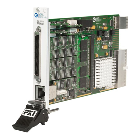
Hardware Hardware Definition PXI/ PCI 61xx (Series 61) controllers from GOEPEL electronic GmbH are programmable intelligent multibus controllers providing various communication interfaces for vehicle network testing and general control applications. The Series 61 controller can generally provide the following features: Basic versions of the communication interfaces: ¨... - Page 14 Hardware The figure below shows the PXI 6153 controller board in its maximum hardware configuration with optional plug-in modules (but without CAN Extension Board): Figure 3-1: P X I 6153 The PCI 6153 board is shown in its basic version (2x CAN): Figure 3-2: P CI 6153 PXI/ PCI 61xx –...
-
Page 15: Technical Data
Hardware Technical Data 3.2.1 General The PXI 61xx controller board is a slot-in board developed for the PXI™ bus. PCI eXtensions for Instrumentation (PXI) is a modular instrumentation platform originally introduced in 1997 by National Instruments and now promoted by the PXI Systems Alliance (PXISA). PXI™... -
Page 16: Series61 Technical Data
Hardware 3.2.3 Series61 The PXI/ PCI 61xx controller board has the following technical specification: Technical Data Symbol Indication Min. Typ. Max. Unit Remarks OnBoard Interfaces CAN/ LIN/ KLine Interfaces (onboard) FlexRay Extension Board FlexRay Extension Board CAN Extension Board CAN Extension Board IO Resources Extension IO Extension Board Digital inputs 1..4 (onboard) -
Page 17: Construction
Hardware Construction 3.3.1 General The core of the PXI/ PCI 61xx controller board builds a strong 600MHz AMCC 460EX PowerPC. This dual-issue, superscalar 32bit RISC CPU is based on the Book-E enhanced PowerPC architecture. With features including out-of-order execution, dynamic branch prediction and a highly pipelined double precise floating-point unit, this processor provides the calculation power required for processing complex residual bus simulation on multiple bus interfaces. - Page 18 Hardware Figure 3-3: PXI 61x x board (schem atically) Figure 3-4: PCI 61x x board (schem atically) PXI/ PCI 61xx – User Manual...
- Page 19 Hardware The PXI/ PCI 61xx controller base board provides 4 digital inputs and 4 digital outputs. By inserting a multi IO module into the third socket, the IOs can be extended by up to 4 digital inputs and 4 digital outputs plus 6 analog inputs and 6 analog outputs.
-
Page 20: Addressing
Hardware 3.3.2 Addressing PXI 61xx boards provide a 1Gbit Ethernet interface and a PXI interface. Both interfaces can be used for the communication of the unit with the host PC. In case of using the Ethernet interface, the boards can be controlled via the default IP Address 192.168.1.62, Port 5134, which can be changed if required (see also Driver... -
Page 21: Isolation
Hardware 3.3.3 Isolation Electric surges can harm expensive test equipment and lead to unreliable test results. Electric isolation protects against electric surges and can help to suppress dangerous electrical transients. It also eliminates ground loops, responsible for data errors due to ground potential differences. -
Page 22: Connector Pinout
Hardware 3.3.5 Connector Used connector: SCSI 68 poles male Pinout Connector for connection cable: SCSI 68 poles female The following table shows the pinout of the frontal connector: Pin Signal Pin Signal CAN1_H LIN1 K-Line1 35 R -CAN1_H UBat extern_iso1 CAN1_L L-Line1 36 R... -
Page 23: Trigger-Connector Pci 61Xx
Hardware 3.3.6 Trigger- According to the trigger and synchronization mechanisms of the PXI technology, the PCI 61xx controller board has a separate Connector TriggerConnector. The functionality of the TRG0..7 and CLK10MHz PCI 61xx signal pins is the same as that of the PXI 61xx board. For the Trigger signals, 5V at most are permissible. -
Page 24: Onboard Interfaces
Hardware 3.3.7 OnBoard The PXI/ PCI 61xx controller board has up to four communication interfaces onboard, designed as CAN, LIN or KLine interface (also Interfaces mixed up possible as multibus version). Two of the communication interfaces have a preferred basic assignment, see Definition. The two others may remain empty, but can optionally designed as further CAN, LIN or KLine interfaces. - Page 25 Hardware Symbol Indication Min. Typ. Max. Unit Remarks CAN V2.0B ISO 11898-1:2003 Interfaces, onboard, Node 1..2 (optionally ..4) Transmission rate Mbit/s UBAT Internal battery voltage detachable intern UBAT External Battery voltage extern Termination high-speed transceiver Ω detachable Termination low-speed transceiver kΩ...
-
Page 26: Flexray Extension Board
Hardware 3.3.8 FlexRay The PXI/ PCI 61xx controller board has two extension sockets on the top side prepared to take on a FlexRay plug-in Extension board Extension Board (see Figure 3-3, Figure 3-4). Each board has an independent FlexRay controller and two FlexRay transceivers, providing full dual channel functionality. -
Page 27: Can Extension Board
Hardware 3.3.9 CAN In the case more CAN interfaces are required, a CAN Extension Board with two CAN interfaces can be plugged in the position of FlexRay Extension Board Node B (generally for CAN5 and CAN6). The TJA1041A highspeed transceivers for these interfaces can not be substituted by other transceiver types. - Page 28 Additional analog and digital inputs and outputs as well as various other interfaces become available by plugging in this extension board. Extension Board GOEPEL electronic GmbH offers two different types: Type1 and Type2. The Type1 IO Extension board has additional resources as follows:...
- Page 29 Hardware The Type2 IO Extension board has additional resources as follows: Symbol Indication min. typ. max. Unit Remarks Digital inputs 5..8 Number of inputs High-level input voltage Low-level input voltage Input current Digital outputs 5..8 Number of outputs High-level output voltage Supply via pin U EXT_IO Low-level output voltage...
-
Page 30: Sent Interfaces
(See section IO-Function in the G-API Help for Software Documentation.) Please note: The SENT interfaces are part of the IO interface. Therefore they do not appear as separate interfaces in the GOEPEL Hardware Explorer. 3-18 PXI/ PCI 61xx – User Manual... -
Page 31: Product Information
Hardware Product Information The Series 61 intelligent, programmable multibus controller family is a highly customizable controller platform. Currently the series consist of four base versions for CAN, LIN/ KLine, FlexRay and Multibus systems that can be combined with a whole number of options. Please refer to the list below for all the options available. - Page 32 Hardware Options for PXI/ PCI 61xx Controller boards Further CAN node for PXI/ PCI 61xx onboard to upgrade on 3 or 4 communication nodes, incl. transceiver module(s) CAN Node Note: The total quantity of installable CAN/ LIN/ KLine nodes at the same time amounts 4 per PXI/ PCI 61xx board without CAN Extension board Additional board for PXI/ PCI 61xx, generally to upgrade on 5 or 6 communication nodes, incl.
- Page 33 Hardware Options for PXI/ PCI 61xx Controller boards Keyword 2000 based on TP1.6 DIAG KW2000 TP1.6 CAN Diagnostic software on board for PXI/ PCI 61xx Keyword 2000 based on TP2.0 DIAG KW2000 TP2.0 CAN Diagnostic software on board for PXI/ PCI 61xx Keyword 2000 based on CAN-ISO-TP DIAG KW2000 ISO-TP CAN Diagnostic software on board for PXI/ PCI 61xx...
-
Page 35: Software
Software Software There are several ways for the embedding of PXI/ PCI 61xx boards in your own applications: G-API Programming ¨ UserCode Programming ¨ Programming via DLL Functions ¨ (Windows Device Driver VISA Device Driver) Programming with LabVIEW ¨ PXI/ PCI 61xx – User Manual... -
Page 36: G-Api Programming
Software G-API Programming The G-API (GOEPEL-API) is the C-based user interface for GOEPEL electronic hardware under Windows ® It provides a wide hardware independent command set for CAN, CAN-FD, LIN/ KLine, MOST, FlexRay, LVDS, SENT, ADIO and Diagnostic services. No matter whether a PXI/ PCI, USB and Ethernet device is used, the commands remain the same. -
Page 37: Usercode Programming
The UserCode run-time module is an option for PXI/ PCI 61xx boards (plus other GOEPEL devices) and requires one license per unit. Executing programs directly on the PowerPC improves the real-time performance remarkable and frees up PCI bandwidth on the host system. - Page 38 Software UserCode programs can be downloaded and debugged direct from Net2Run IDE via an Ethernet connection. The figure below shows the Net2RunIDE development system: Figure 4-1: N et2R un IDE W indow Please consult the G-API documentation for further information. This documentation and the installation software are located in the G-API folder of the supplied “Product Information”...
-
Page 39: Programming Via Dll Functions
Software Programming via DLL Functions For the used structures, data types and error codes refer to the headers – you find the corresponding files on the supplied CD. PXI/ PCI 61xx – User Manual... -
Page 40: Windows Device Driver
Software 4.3.1 Windows ® The DLL functions for programming using the Windows device driver are described in the following chapters: Device Driver System Info ¨ Transceiver Info ¨ Write Instruction ¨ Read Response ¨ Read Response Block ¨ PXI/ PCI 61xx – User Manual... -
Page 41: System Info
Software 4.3.1.1 System Info The Pxi61xx__SystemInfo function is used for the status query of the hardware driver and for query of the board properties. Format: S32 Pxi61xx__SystemInfo(t_System_Info *pSystemInfo, LengthInByte); Parameters: Pointer, for example pSystemInfo, to a data structure (For the structure, see the Pxi61xx.h file on the supplied CD) LengthInByte... -
Page 42: Transceiver Info
Software 4.3.1.2 Transceiver The Pxi61xx__TransceiverInfo returns information regarding the Info plugged-in transceivers as well as their number. Format: S32 Pxi61xx__TransceiverInfo(t_Transceiver_Properties *pTransceiverProperties, LengthInByte); Parameters: Pointer, for example pTransceiverProperties, to a data structure Pxi61xx.h (For the structure, see the file on the supplied CD) LengthInByte Size of the buffer pTransceiverProperties is pointing to, in bytes Description:... - Page 43 Software 4.3.1.3 W rite The Pxi61xx__WriteInstruction function is for sending a command to Instruction the PXI/ PCI 61xx controller. Format: S32 Pxi61xx__WriteInstruction(U8 *pData, DataLength); Parameters: Pointer, for example pData, to the writing data area, consisting of Command header and Command bytes (At present max.
- Page 44 Software 4.3.1.4 R ead The Pxi61xx__ReadResponse function is for reading a response from R esponse the PXI/ PCI 61xx controller. Format: S32 Pxi61xx__ReadResponse(U8 Device, U8 *pData, U32 *DataLength); Parameters: Device Index of the PXI/ PCI 61xx board, beginning left with 1 Pointer, for example pData, to the reading data area, consisting of Response header and Response bytes...
- Page 45 Software 4.3.1.5 R ead The Pxi61xx__ReadResponseBlock function is for reading all available R esponse Block responses from the PXI/ PCI 61xx controller. Format: S32 Pxi61xx__ReadResponseBlock(U8 Device, U8 *pData, U32 *DataLength, U32 *BlockCounter); Parameters: Device Index of the PXI/ PCI 61xx board, beginning left with 1 Pointer, for example pData, to the reading data area, consisting of Response header and Response bytes...
-
Page 46: Write Instruction
Software 4.3.2 VISA The DLL functions for programming using the VISA device driver are described in the following sections: Device Driver Init ¨ Done ¨ System Info ¨ Transceiver Info ¨ Write Instruction ¨ Read Response ¨ 4-12 PXI/ PCI 61xx – User Manual... -
Page 47: Init
Software 4.3.2.1 Init The PXI61xx_Init function is for opening VISA sessions for the system’s PXI/ PCI 61xx boards including initialization. Format: ViStatus PXI61xx_Init(ViUInt32 *CardCount); Parameter: CardCount Number of the system’s PXI/ PCI 61xx boards recognized by the VISA driver. Description: The PXI61xx_Init function searches for all PXI/ PCI 61xx boards of the system and opens the required sessions. -
Page 48: System Info
Software 4.3.2.3 System Info The PXI61xx_SystemInfo function provides general driver and board information. Format: ViStatus PXI61xx_SystemInfo(t_System_Info *DriverData, ViUInt32 LengthInByte, ViChar *DeviceName); Parameters: Pointer, for example DriverData, to a data structure PXI61xx_API.h (For the structure, see the file on the supplied CD) LengthInByte Size of the buffer DriverData is pointing to, in bytes DeviceName... -
Page 49: Transceiver Info
Software 4.3.2.4 Transceiver The PXI61xx_TransceiverInfo function provides information regarding Info the plugged-in transceivers as well as their number. Format: ViStatus PXI61xx_TransceiverInfo(t_Transceiver_Properties *TransceiverProperties, ViUInt32 LengthInByte); Parameters: Pointer, for example TransceiverProperties, to a data structure PXI61xx_API.h (For the structure, see the file on the supplied CD) LengthInByte Size of the buffer TransceiverProperties is pointing to, in bytes Description:... -
Page 50: Write Instruction
Software 4.3.2.5 W rite The PXI61xx_WriteInstruction function is for writing data Instruction to the PXI/ PCI 61xx controller. Format: ViStatus PXI61xx_WriteInstruction(ViUInt8 *pData, ViUInt16 DataLength); Parameters: Pointer, for example pData, to the writing data area, consisting of Command Header and Command Bytes (currently max. -
Page 51: Read Response
Software 4.3.2.6 R ead The PXI61xx_ReadResponse function is for reading data R esponse from the PXI/ PCI 61xx-Controller. Format: ViStatus PXI61xx_ReadResponse(ViUInt8 Device, ViUInt8 *pData, ViUInt32 *DataLength); Parameters: Device Index of the PXI/ PCI 61xx board, beginning left with 1 Pointer, for example pData, to the reading data area, consisting of Response Header and Response Bytes (currently max. -
Page 52: Programming With Labview
The supplied CD contains VIs for activating PXI/ PCI 61xx boards under LabVIEW. via the G-API These LabVIEW VIs use the functions of the GOEPEL G-API. 4.4.2 LLB using The supplied CD contains VIs for activating PXI/ PCI 61xx boards under LabVIEW. -
Page 53: Dditional Oftware Nterfaces
Software Additional Software Interfaces 4.5.1 FS The Software Interface “FS1” (File System) allows, amongst others, creating, copying, deleting, executing and searching of files on the hardware. Thus, it allows uniform access to the OnBoard File System. 4.5.2 Net2Run The Software Interface “Net2Run” (Net2Run1..Net2Run4) serves for the creation, configuration and execution of Residual bus simulation. -
Page 54: Usercode
FIFO. Further GOEPEL Software PROGRESS, Program Generator and myCAR of GOEPEL electronic GmbH are comfortable software programs for testing with GOEPEL hardware. Please refer to the corresponding User Manual to get more information regarding these programs. - Page 55 Index Addressing LabVIEW Ethernet ......3-8 G-API ......4-18 PXI ....... 3-8 VISA ......4-18 Windows ..... 4-18 CAN Extension ....3-15 Communication Interfaces .. 3-7 myCAR ......4-20 Connector ....... 3-10 Controller Command sending ..4-9 Data reading ....4-17 Net2Run ......
- Page 56 Index VISA Driver ..... 4-12 Windows driver ..2-2, 4-6 VISA session Closing ......4-13 Opening ...... 4-13 PXI/ PCI 61xx – User Manual...
Need help?
Do you have a question about the PXI 61 Series and is the answer not in the manual?
Questions and answers