Table of Contents
Advertisement
Quick Links
Advertisement
Table of Contents

Related Manuals for Goepel G PCIe 6281

Summary of Contents for Goepel G PCIe 6281
- Page 1 G PCIe 6281 Manual (Original documentation)
- Page 2 The contents of the manual is subject to change without prior notice and is supplied for information only. Hardware and software might be modified also without prior notice due to technical progress. In case of inaccuracies or errors appearing in this manual, GOEPEL electronics GmbH assumes no lia- bility or responsibility.
-
Page 3: Table Of Contents
G PCIe 6281 Table of Contents 1 Introduction ..........................1 1.1 Notes on this document ...................... 1 1.2 Intended Use ........................1 1.3 EMC Protection Measures ....................2 1.4 EU Declaration of Conformity ....................2 1.5 General Safety Regulations ....................2 1.6 Liability and Warranty Exclusion ................... 2 1.7 Supplied Accessories ......................3 2 Commissioning .......................... - Page 4 G PCIe 6281 6.2 Disposal of used Disposable Batteries / Rechargeable Batteries ..........23 Index ............................24 A Declaration of Conformity ......................25 G PCIe 6281...
- Page 5 2.2 Example IP address of the network adapter ..................6 2.3 HardwareExplorer with G PCIe 6281 Multibus Controller ..............6 3.1 Overview G PCIe 6281 as PCIe ...................... 9 3.2 Block Diagram of the G PCIe 6281 Multibus Controller ..............11 3.3 Numbering of the RJ.5 connectors ....................11 G PCIe 6281...
- Page 6 G PCIe 6281 List of Tables 1.1 Symbols ........................... 1 3.1 Components of the G PCIe 6281 PCIe board ..................9 3.2 General Specifications ....................... 10 3.3 General Electrical Specifications ....................10 3.4 Pin assignment of the RJ.5 connector ..................11 3.5 Pin assignment of the D-SUB9 sockets of the adapter cable ............. 12 3.6 Article numbers of the TE Connectivity adapter cables ..............
-
Page 7: 1 Introduction
1.1 Notes on this document This document applies only to the device type G PCIe 6281 . Any handling of the device requires the exact knowl- edge and observance of this manual. The operational safety and the function of the device can only be guaran- teed if both the general safety and accident prevention regulations of the legislator and the safety instructions in the manual are observed. -
Page 8: Emc Protection Measures
1.6 Liability and Warranty Exclusion The G PCIe 6281 has not been developed, tested or intended for use in safety-related applications. Do not use the device for safety-related systems or vehicle subsystems. The use of such a device within motor vehicles to control the main vehicle functions can be dangerous and lead to malfunction of motor vehicles. -
Page 9: Supplied Accessories
1 Introduction 1.7 Supplied Accessories As accessories to G PCIe 6281 Multibus Controller you get: Series 62 Multibus Controller as PCIe board • • CD with driver, software and manual G PCIe 6281... -
Page 10: 2 Commissioning
(DUT). 2.3 Driver Installation The G PCIe 6281 Multibus Controller can be operated under Windows 7, 8 and 10 as well as under Linux. 2.3.1 Windows Device Driver PCIe devices can run on Windows 7, 8 and 10. The plug-and-play capability of Windows automatically launches a driver installation for each newly detected hardware component through the Hardware Wizard. -
Page 11: Network Configuration
The IP-Address of the G PCIe 6281 Multibus Controller must be different from that of the network • adapter. The subnet mask must be set to a value such that both IP addresses ( G PCIe 6281 Multibus Controller • and network adapter) are located in the same subnet. - Page 12 Figure 2.2 Example IP address of the network adapter After the network adapter has been set up correctly, the G PCIe 6281 Multibus Controller can be addressed di- via its IP address. The IP address of the G PCIe 6281 Multibus Controllers...
-
Page 13: Firmware Update
(In such a case, reinstalling the correct firmware variant can restore the functionality.) To update the firmware, do the following: • Download the latest firmware update file from genesis.goepel.com Open the GOEPEL electronics HardwareExplorer • • Right-click on the selected device (for example "PCIe6281") and select "Flash Firmware" •... -
Page 14: 3 Technical Description
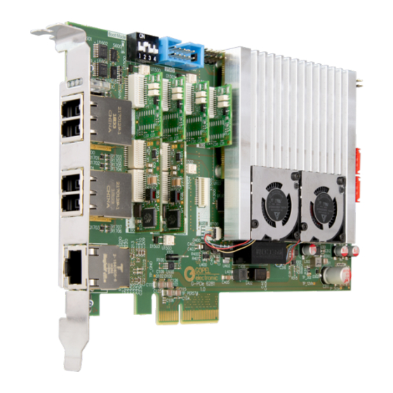
3 Technical Description 3.1 Product Description The G PCIe 6281 Multibus Controller is an industrial test system from GOEPEL electronics with a wide range of applications and high flexibility. This test system is specially adapted to the needs and transmission standards in the vehicle sector. -
Page 15: Overview Of G Pcie 6281 Multibus Controller
The G PCIe 6281 Multibus Controller is designed as PCIe Version 2.1 and has 4 lanes. It has a bandwidth of 5 GBit/s per lane and a maximum transfer rate of 2 GByte/s (without protocol overhead). -
Page 16: Technical Specifications
3.4 Design and Function The G PCIe 6281 Controller has been developed as a highly flexible multibus controller platform. It offers up to eight serial bus interfaces and another eight digital I/O interfaces. The bus interfaces can be configured in nu- merous variants. -
Page 17: Block Diagram
3 Technical Description 3.4.1 Block Diagram Figure 3.2 Block Diagram of the G PCIe 6281 Multibus Controller 3.4.2 Pin Assignment For connecting the communication interfaces a total of four RJ.5 connectors are provided. On each of the RJ.5 connectors are the signals from two bus interfaces and one digital IN and one digital OUT signal. -
Page 18: Lan/ Ethernet
3.4.3 LAN/ Ethernet The board has an RJ45 Ethernet socket for configuring and controlling the G PCIe 6281 Multibus Controller us- ing a PC. If necessary, if the board is e.g. in a rack that is only for power, this interface can act as a host interface. -
Page 19: Leds/ Status Indication
3 Technical Description 3.4.4 LEDs/ Status Indication The LEDs arranged on the front panel provide information about the current operating status of the G PCIe 6281 Multibus Controller. The display states of the LEDs are explained in the following table: LED1... -
Page 20: Onboard Interfaces
Due to the large number of possible variants, how the various bus interfaces can be connected to the transceiv- er slots some variants were defined in order to be able to handle these on the firmware side. The G PCIe 6281 Multibus Controller can be equipped with these variants. -
Page 21: Can/ Can Fd
3 Technical Description 3.5.1 CAN/ CAN FD The G PCIe 6281 Multibus Controller supports a total of eight CAN/ CAN FD interfaces. For CAN and CAN FD the same transceiver is used: • TJA1044GT The following specifications apply to the transceiver: Symbol Parameter Min. -
Page 22: Flexray
3.5.3 FlexRay The G PCIe 6281 Multibus Controller supports a total of two FlexRay interfaces. Since a FlexRay transceiver can map either the A or B channel, two slots are required per interface. For the total of two possible FlexRay inter- faces, a total of 4 slots are occupied. -
Page 23: Digital Io
3.5.5 Digital IO The G PCIe 6281 Multibus Controller supports a total of eight interfaces for Digital I/O. Of these four interfaces can be used as a digital input and four as a digital output. These are firmly installed on the board. -
Page 24: 4 Software
G-API folder of the supplied "Product Information" CD 4.2 Programming via LabVIEW The supplied CD contains a VI collection that can be used to access the G PCIe 6281 Multibus Controller under LabVIEW. The LabVIEW VIs use the functions of the G-API . -
Page 25: Additional Software Interfaces
4 Software UserCode programs can be downloaded and debugged directly from the Net2Run IDE via an Ethernet connec- tion. 4.4 Additional Software Interfaces 4.4.1 File System The software interface "FS" (File System) allows, among others, to create, copy, delete, run, and finding files on the hardware. -
Page 26: Reset The Device
4 Software 4.5 Reset the Device The Series 62 Multibus Controller starts automatically when the power is turned on. During operation, a software reset of the device may be performed via the API to reset the configurations to their default values. Each interface can be initialized individually or all interfaces together. To initialize an interface, the command G_Common_InitInterface can be used. -
Page 27: 5 Service And Support
UserCode programs. This option is required for each Series 62 Multibus Controller. Table 5.1 Additional options for the Series 62 Multibus Controller If necessary, please contact our sales department: GOEPEL electronics GmbH ATS-Vertrieb Goeschwitzer Str. 58 / 60 D-07745 Jena Tel.: +49-3641-6896-508... -
Page 28: Warranty And Repair
If the warranty has expired, we will of course also repair your test system in accordance with our general installation and service conditions. If necessary, please contact our support service: GOEPEL electronics GmbH ATS-Support Goeschwitzer Str. 58 / 60 D-07745 Jena Tel.: +49-3641-6896-597... -
Page 29: 6 Disposal
6 Disposal 6 Disposal 6.1 Disposal of used Electrical / Electronic Equipment The device implements the following EU directives: • 2012/19/EU (WEEE) Waste Electrical and Electronic Equipment and • 2011/65/EU on the restriction of the use of certain hazardous substances in electronic equipment (RoHS directive) At the end of the life of the device, this product must not be disposed of with other household waste. - Page 30 Index Index Power Supply, 13 Product Description, 8 Reset, 20 Accessories, 3 Addressing, 5 Automotive Ethernet, 16 Safety, 2 SENT, 17 Sequence, 19 CAN/ CAN FD, 15 Software, 18 Components, 9 Specifications, 10 Status Indication, 13 SYNC, 13 Digital I/O, 17 System Requirements, 4 Disposal, 23 Driver, 4...
- Page 31 Appendix A Declaration of Conformi- Appendix A Declaration of Conformity G PCIe 6281...
Need help?
Do you have a question about the G PCIe 6281 and is the answer not in the manual?
Questions and answers