Table of Contents
Advertisement
Quick Links
Advertisement
Table of Contents

Related Manuals for CORA CS1030


Summary of Contents for CORA CS1030
- Page 1 CS1030 Wall Receptacle Outlet User Guide Long-range, switchable, wall receptacle outlet supporting LoRaWAN or Coralink wireless protocols. Ideal for applications in smart-building, home automation, and smart city lighting and control. Version: 1.0 February 2022...
-
Page 2: Table Of Contents
CS1030 Long Range Wall Receptacle Outlet – User Guide Contents Getting Started ........................... 3 What’s In the Box ........................3 Registering / Claiming the Device ................... 4 User Interface ......................... 5 Push Button ........................5 Status Indicators ......................... 6 Attaching to the Network ......................6 About LoRaWAN ........................ -
Page 3: Getting Started
Coralink wireless protocols. The 120V, 15-amp rated unit also provides a 2.4 Amp USB Type A output. One device outlet can be controlled remotely or configured to turn on/off automatically with built-in scheduler, while the other outlet is always on. The CS1030 supports advanced scheduling capabilities including dynamic sunrise or sunset alarms, repetitive alarms, and advanced programmable schedule triggers that can be initiated by LoRaWAN. -
Page 4: Registering / Claiming The Device
Figure 2 – CS1030 QR claim key simplifies device registration and activation. Once the device is registered or claim. The application provider will have secure access to the device identity information, which will allow provisioning the device on any supported LoRaWAN network. -
Page 5: User Interface
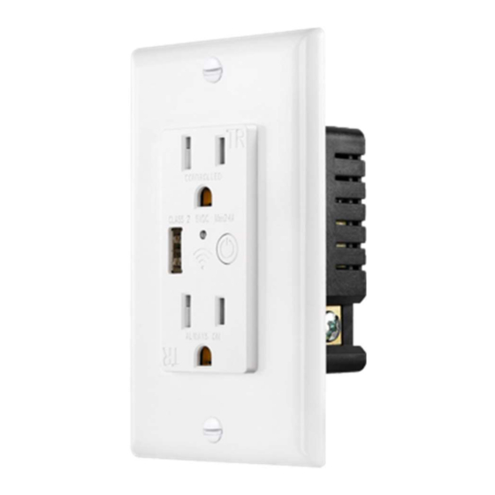
User Interface The CS1030 user interface is shown in the figure below. Figure 3 – Performing Network or Factory Reset on the Wall Outlet The device provides one switched outlet and one always-on outlet, a 2.4A (5V) USB charger, an LED Indicator, and a push button. -
Page 6: Status Indicators
Switchable Outlet Off (de-energized) Attaching to the Network Once AC Power is connected, the CS1030 will automatically attempt to join the LoRaWAN network automatically and the Status LED will blink continuously. After a while, the join schedule will become less aggressive and up to 12 hours will elapse between join attempts. To immediately force the CS1030 to join, perform a Network Reset operation. -
Page 7: About Lorawan
(unconfirmed) protocols used for IP networks. Before a device, such as the CS1030 Wall Outlet can transmit messages using LoRaWAN it must go through a “join” process. The Join process involves key-exchange with the cloud- hosted network provider (The Things Network, Helium, etc.) and is defined in the LoRaWAN protocol standard. -
Page 8: Installation
CS1030 Long Range Wall Receptacle Outlet – User Guide Installation Important Safety Notice If you are not comfortable working with 120V electrical wiring, please consult or hire a qualified electrician. Turn off circuit(s) at the breaker or fuse panel and confirm there is no voltage in the box before starting the installation (there may be multiple live circuits within the switch box). - Page 9 CS1030 Long Range Wall Receptacle Outlet – User Guide Unscrew the outlet from the electrical box and pull it out with the wires still attached. Three wires will be attached to the outlet: an incoming line (hot) wire, which is black;...
- Page 10 CS1030 Long Range Wall Receptacle Outlet – User Guide Gently push the new, wired outlet back into the electrical box and screw it in place. Secure the outlet to the box with the two screws. Snap on the plate and affix with the provided screws.
- Page 11 The status indicator should be green. Press the push button again to turn off the switched outlet. CS1030 Wall Outlet installation is complete and is now ready for use and/or additional configuration. Page 11...
-
Page 12: Event Notifications And Reports
CS1030 Long Range Wall Receptacle Outlet – User Guide Event Notifications and Reports The CS1030 Wall Outlet has the following event notifications: Outlet Socket Notifications: Outlet ON (energized) – The outlet is powered on (default enabled) Outlet OFF (de-energized) – The outlet is powered off (default enabled) Additionally, statistics can be enabled to report aggregate outlet socket event activity: ... -
Page 13: Reset Notifications
CS1030 Long Range Wall Receptacle Outlet – User Guide Reset Notifications FACTORY RESET uplink messages will be sent after rebooting. Firmware Version The firmware information can be retrieved via sending a downlink command. See Configuration and Integration for details. Page 13... -
Page 14: Configuration And Integration
CS1030 Long Range Wall Receptacle Outlet – User Guide Configuration and Integration The CS1030 supports the following settings and features, which are configured via downlink messages. Configuration Description Units Default Set/Get State Turn the switch on/off Set the device current time and... -
Page 15: Specifications
The magnitude of localized heating increases as the current draw of the connected load increases. The temperature sensor of the CS1030 is located inside the socket-housing. Therefore, the temperature measurements obtained from the CS1030 should be considered a rough estimate of ambient temperature around the unit. -
Page 16: Dimensions
CS1030 Long Range Wall Receptacle Outlet – User Guide Dimensions Page 16... -
Page 17: Ordering Information
CS1030 Long Range Wall Receptacle Outlet – User Guide Ordering Information Communication Options Prior to ordering, determine the communication requirements: Application Protocol: Untethered XMF or CP-Flex OCM Network Protocol: LoRaWAN or Coralink Operating Region and Frequency: US915, EU868, CN470 (others available upon request) ... - Page 18 CS1030-UL-US9HT-00 – Wall Outlet for U.S. region, untethered, supporting Helium and TTN sub-band 2. CS1030-UL-EU8ST-00 – Wall Outlet for Europe region, untethered, standard configuration. CS1030-CL-US9HT-00 – Wall Outlet configured for Cora OCM and CP-Flex cloud stack integration, Supports OCM V2 protocol specifications. Page 18...
-
Page 19: Fcc Statement
CS1030 Long Range Wall Receptacle Outlet – User Guide FCC Statement This equipment has been tested and found to comply with the limits for a Class B digital device, pursuant to part 15 of the FCC Rules. These limits are designed to provide reasonable protection against harmful interference in a residential installation.
Need help?
Do you have a question about the CS1030 and is the answer not in the manual?
Questions and answers