
Subscribe to Our Youtube Channel
Related Manuals for UUGear PiGear Nano

Summary of Contents for UUGear PiGear Nano
- Page 1 PiGear Nano: Nano-ITX Raspberry Pi Compute Module 4 Carrier Board User Manual (revision 1.04) Copyright © 2022 Dun Cat B.V. & THLAB, All rights reserved. UUGear is a trade name of Dun Cat B.V.
-
Page 2: Table Of Contents
10.2 Controller Area Network (CAN) Bus ............... 24 10.3 1-Wire Interface ..................... 25 10.4 Analog Inputs (A/D Converter) ................26 10.5 Digital Inputs ......................30 Copyright © 2022 Dun Cat B.V. & THLAB, All rights reserved. UUGear is a trade name of Dun Cat B.V. - Page 3 Fan Connector ......................42 Power and Reset Button Connectors ................42 Case Kit for PiGear Nano ....................42 Revision History ......................43 Copyright © 2022 Dun Cat B.V. & THLAB, All rights reserved. UUGear is a trade name of Dun Cat B.V.
-
Page 4: Product Overview
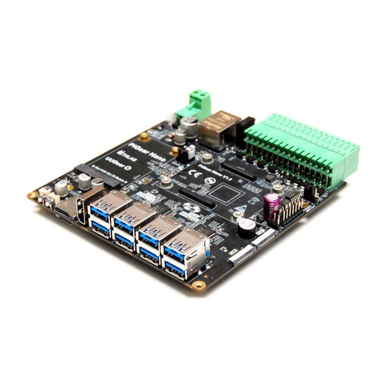
1. Product Overview PiGear Nano is a high performance Nano-ITX (12x12cm) carrier board for Raspberry Pi Compute Module 4. PiGear Nano is mainly designed for industrial applications, but you can also use it as office computer, family media center, gaming console etc. -
Page 6: Specification / Technical Details
2. Specification / Technical Details Gigabit-Ethernet RJ45 socket x 1 MINI PCIE LTE/4G/GPRS interface x 1 Network On-board SIM card slot x 1 USB 3.0 Type-A connector x 8 USB 2.0 Type-C connector x 1 (for flashing CM4, or powering the board with light load) 18-bit ADC input x 4 Digital input x 4 Analog &... -
Page 7: Package Content
Temperature -30°C~80°C (-22°F~176°F) Humidity 0~80%RH, no condensing Operating Environment No corrosive gas 3. Package Content Each package of PiGear Nano contains: PiGear Nano board x 1 6x6x5 heat sink x 1 (for VL805 chip on the back of the board) ... -
Page 8: Connect Raspberry Pi Compute Module 4 To The Board
4. Connect Raspberry Pi Compute Module 4 to the Board Before starting, it is recommended to install four metal standoffs underneath so the board can lay flat on the desk. You can find four metal standoffs and four screws in the package. Just place the standoff under the mounting hole and use a screw to secure it. - Page 9 If you will use the device in a vibrating environment, you may want to secure your Raspberry Pi Compute Module 4 on the board with four M2.5 screws (not included in the package). It is also recommended to put the small heatsink (included in the package) on the VL805 chip on the back of the board.
-
Page 10: Installing Operating System
CM4 will boot in USB mass storage mode, and you can flash the disk image into it. Now connect a USB Type-C cable to PiGear Nano, and connect the other end of the cable to your computer. This USB cable will power your PiGear Nano during the installation process, and there is... -
Page 11: For Raspberry Pi Cm4 Lite (Without Emmc)
After flashing the OS disk image into the "boot" drive, please don't forget to remove the jumper cap from the "Disable eMMC Boot" jumper, so that your PiGear Nano now works as a standalone computer system. -
Page 12: Powering Pigear Nano
If you have installed the OS into your CM4's eMMC, or you have inserted an SD card with OS installed, you can power the board and boot the system. You can power PiGear Nano with DC 7~30V via the universal 2-pin power connector, or you can power it with DC 5V via the USB Type-C connector. - Page 13 Install UUGear Web Interface (UWI). It is recommended to download and run the installation script in home directory. You can run this command to download the installation script: pi@raspberrypi:~ $ wget https://www.uugear.com/repo/PiGearNano/installPiGearNano.sh Then you can run the script with sudo: pi@raspberrypi:~ $ sudo sh ./installPiGearNano.sh...
-
Page 14: Jumper Settings
With the software installed, the e-latching power switch is supported on software level. However, you still need to remove the "bypass power switch" jumper cap, otherwise PiGear Nano cannot fully cut the power after system shutdown. If you do not want to use the e-latch power switch, you can keep... - Page 15 In addition, you will need to put a jumper cap on the "Default ON" jumper. This is to let you choose whether your PiGear Nano will automatically boot up when the power supply is connected. If you put the jumper cap on pin 3-2, it will not boot up until you tap the power button.
- Page 16 There is also a 3-pin "wireless" jumper above the DISP0 connector, which is for disabling WiFi or Bluetooth. Shorting pin 1-2 to disable WiFi Shorting pin 2-3 to disable Bluetooth There is also a multifunctional 2x7 pin jumper between the "reset" jumper and the "wireless" jumper. It is actually the same as the J2 header on Raspberry Pi Compute Module 4 official I/O board.
-
Page 17: Software Usage
9. Software Usage The software will be installed in a directory named "pgnano", while the UUGear Web Interface will be installed in a directory named “uwi”. You can run the software by running the PiGearNano.sh script: pi@raspberrypi:~ $ cd pgnano pi@raspberrypi:~/pgnano $ ./PiGearNano.sh... -
Page 18: Realtime Clock
9.1 Realtime Clock Here you can see the system time and the time in the real-time clock (RTC). You can write the system time into real-time clock or the other way around. You can also use Internet time to synchronize the system time and RTC time. You can press ENTER to refresh the time display. ============================================================ Realtime Clock ============================================================... -
Page 19: Analog Inputs (Adc)
9.2 Analog Inputs (ADC) Here you can configure the ADC‟s sampling rate (SPS) and Programmable Gain Amplifier (PGA). The current code value and actual voltage on each analog input is also listed here. You can press ENTER to refresh the view. ============================================================ Analog Inputs (ADC) ============================================================... -
Page 20: Digital Inputs
9.3 Digital Inputs The current values of digital inputs are listed here. You can press ENTER to refresh the view. ============================================================ Digital Inputs ============================================================ +-----+-----+-----+-----+ |DI-1 |DI-2 |DI-3 |DI-4 | +-----+-----+-----+-----+ | 0 | 0 | 0 | 0 | +-----+-----+-----+-----+ 1. -
Page 21: Digital Outputs
9.4 Digital Outputs Here you control each digital output, and set it to HIGH (1) or LOW (0). ============================================================ Digital Outputs ============================================================ +-----+-----+-----+-----+ |DO-1 |DO-2 |DO-3 |DO-4 | +-----+-----+-----+-----+ | 0 | 0 | 0 | 0 | +-----+-----+-----+-----+ 1. Set DO-1 output LOW 2. -
Page 22: Configurable Digital Inputs/Output
9.5 Configurable Digital Inputs/Output Not every digital input/output (DIO) can be configured to IN or OUT mode separately, however you can choose four different combinations here. ============================================================ Configurable Digital Inputs/Output ============================================================ +-----+-----+-----+-----+ |DIO-1|DIO-2|DIO-3|DIO-4| +-----+-----+-----+-----+ | IN | IN | IN | IN | +-----+-----+-----+-----+ | 0 | 0 | 0 | 0 | +-----+-----+-----+-----+... -
Page 23: Uwi Usage
9.8 UWI Usage UWI is a mini web server that only uses very little system resource, while it allows you to monitor and configure your board via any device that can access the network. By default, UWI can be accessed via http://raspberrypi:8000/pgnano/. If you cannot access it, most probably is because the host name “raspberrypi”... -
Page 24: X16 Quick Cable Connector
10. 2x16 Quick Cable Connector PiGear Nano offers wide range of input/output and communicating interfaces, which are routed to the green 2x16 quick cable connector. On the back of the board, you will also see the silkscreens that mark the functionality of each pin. -
Page 25: Serial Port
10.1 Serial Port PiGear Nano implements 4 serial ports, and they are accessible via the 2x16 quick cable connector: They occupy UART1, UART3, UART4 and UART5, and they aremapped to different devices in the system. Name Mapped Device in System... - Page 26 And here is the schematic for RS485: Both RS485 channels work in Half-Duplex mode, and they do not need additional I/O pin to control the transmitting direction.
-
Page 27: Controller Area Network (Can) Bus
10.2 Controller Area Network (CAN) Bus PiGear Nano has one CAN bus, which can be access on pin 22 and 23 in the 2x16 quick cable connector. PiGear Nano uses chip MCP2515 to provide CAN controller, which talks to Raspberry Pi Compute... -
Page 28: 1-Wire Interface
10.3 1-Wire Interface PiGear Nano has 1-wire channel on pin 3 in the 2x16 fast cable connector. PiGear Nano uses chip DS2482 to implement a single-channel 1-wire master device, which talks to Raspberry Pi Compute Module 4 via the I2C-1 interface. -
Page 29: Analog Inputs (A/D Converter)
10.4 Analog Inputs (A/D Converter) PiGear Nano has four analog inputs: PiGear Nano uses chip MCP3424 to provide four-channel, low-noise, high accuracy A/D converter with up to 18-bit resolution. The A/D converter talks to Raspberry Pi Compute Module 4 via the I2C-6 interface. - Page 30 Resolution Data Rate Minimum Code Maximum Code 12 bits 1 mV 240 SPS 2047 250uV 60 SPS 8191 14 bits 16 bits 62.5uV 15 SPS 32767 18 bits 15.625uV 3.75 SPS 131071 There is an 8-bit configuration register in MCP3424, and you can make configurations by changing specific bits.
- Page 31 If you want to measure voltage higher than 11.6V, then you will need to implement your own voltage divider. R1 and R2 should be properly chose so the actual voltage applies to ADC is no higher than 11.6V. In this case, the formula is changed to: ) ×...
- Page 32 Usually �� is a rather small resistor. If �� is 0.01 Ω, and the voltage drops on �� ���������� ���������� ���������� 0.0125V, the current can be calculated like this: �� 0.0125 �������� = 1.25 �� �� 0.01 ����������...
-
Page 33: Digital Inputs
10.5 Digital Inputs PiGear Nano has four digital inputs. The four digital inputs are implemented by chip PCF8574, which talks to Raspberry Pi Compute Module 4 via the I2C-1 interface. Each digital input can bear up to 12V. Voltage below 0.5V is considered as LOW. -
Page 34: Digital Outputs
10.6 Digital Outputs PiGear Nano has 4 digital outputs. These 4 digital outputs are open drain outputs and they are driven by GPIO-11, GPIO-16, GPIO-17 and GPIO-22 in Raspberry Pi Compute Module 4 (please see table below). CM4 GPIO GPIO-11... -
Page 35: Configurable Digital Inputs/Outputs
10.7 Configurable Digital Inputs/Outputs PiGear Nano also comes with four configurable digital I/O pins. These four pins can be configured as either inputs or outputs. DIO-1 and DIO-2 are in one group, while DIO-3 and DIO-4 are in another group. The pins in the same group must be in the same input/output mode. - Page 36 10.7.1 Configuration 1 (four inputs): In order to configure all of them as inputs, you need to set the register in both chips to 0xF0: Address Register Index Set to Value I2C-1 0x20 omitted 0xF0 (B11110000) I2C-6 0x20 omitted 0xF0 (B11110000) Then you can inquire the pin status via I2C-1 (address=0x20, omitting register index), and the pin status are stored in bit 4~7 in the register.
- Page 37 Value 0 / 1 0 / 1 0 / 1 0 / 1 DIO-4 DIO-3 DIO-2 DIO-1 Remarks: GPIO-23 (BCM naming) will be pulled down when new data is available on inputs, and you can monitor GPIO-23 and know when to query the new data. 10.7.3 Configuration 3 (DIO-1 and DIO-2 as outputs;...
-
Page 38: Pcie
DIO-1 11. PCIE PiGear Nano extends 4 channels of USB3.0 interfaces from the PCIE on Raspberry Pi Compute Module 4, and then extends a PCIE Gen3 x2 (via RTL9210B-CG) for NVME SSD, a Mini PCIE for 4G LTE module, and also 8 USB 3.0 ports. -
Page 39: Nvme Ssd
There is a NVME SSD M.2 connector on the back of PiGear Nano board, and you can connect an M.2-2280 NVME SSD to it. There is a green LED (D12) on the top surface of PiGear Nano board, and it will blink when SSD is transmitting data. - Page 40 Remarks: connecting two SIM cards to both SIM card slots will not work. PiGear Nano uses GPIO-6 to control the power supply to the 4G LTE module, and uses GPIO-7 to reset the module. If you install the software for PiGear Nano, the daemon.sh script will automatically configure GPIO-6 and GPIO-7 to enable the 4G LTE module (if present).
-
Page 41: Usb3.0
11.3 USB3.0 PiGear Nano comes with 8 USB 3.0 ports, and each of them has its own activitiy indicator (green LED) near the VL817 chips. Limited by Raspberry Pi CM4‟s PCI Express Gen 2 lane, these 8 USB 3.0 ports share a total of 4Gbps of data bandwidth. -
Page 42: Realtime Clock (Rtc)
12. Realtime Clock (RTC) PiGear Nano uses PCF85063 realtime clock for system time keeping, and the RTC talks to Raspberry Pi Compute Module 4 via I2C-1 interface. PCF85063 has very small quiescent current (0.22µA) and PiGear Nano uses a 3V 1F supper capacitor (BT1) for off-power time keeping. -
Page 43: Dsi And Csi
13. DSI and CSI PiGear Nano has one DSI connector (DISP0) and one CSI connector (CAM0). Different than the official Raspberry Pi Compute Module 4 I/O board, PiGear Nano uses I2C-1 instead of I2C-0 for DSI and CSI. If you will use them, please run these commands in home directory and then reboot: sudo cp pgnano/bin/dt-blob.bin /boot/dt-blob.bin... -
Page 44: Sd Card Slot
14. SD Card Slot There is an SD card slot on PiGear Nano board. You can insert a micro SD card into it. It is used only when you connect Raspberry Pi Compute Module 4 Lite (without eMMC) to PiGear Nano. -
Page 45: Fan Connector
Aside the power button and reset button, there are two small connectors. Which allow you to connect external momentary push buttons and route them to different location. 19. Case Kit for PiGear Nano It is possible to put PiGear Nano into a case. We have designed a black case kit for PiGear Nano,... -
Page 46: Revision History
20. Revision History Revision Date Description 1.00 2022.01.09 Initial revision Fix some typo. Add description about how to enable 4G LTE module. 1.01 2022.01.21 Add description about the small heatsink in the package. Add description about fan connector and power/reset button connectors. Add more details about enabling 4G LTE module.
Need help?
Do you have a question about the PiGear Nano and is the answer not in the manual?
Questions and answers