
Related Manuals for MasterCraft 055-0216-8

Summary of Contents for MasterCraft 055-0216-8
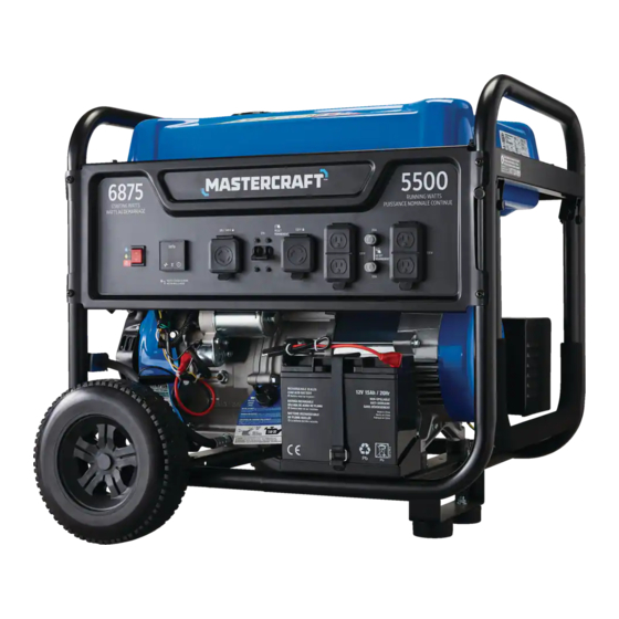
- Page 1 MODEL NO. 055-0216-8 GAS-POWERED PORTABLE GENERATOR INSTRUCTION IMPORTANT: Please read this manual carefully before operating the generator and save it for reference. MANUAL...
-
Page 3: Table Of Contents
TABLE OF CONTENTS SAFETY DEFINITIONS IMPORTANT SAFETY INSTRUCTIONS CONTROLS AND FEATURES ASSEMBLY OPERATION MAINTENANCE STORAGE GENERATOR SPECIFICATIONS ENGINE SPECIFICATIONS OIL SPECIFICATIONS FUEL SPECIFICATIONS BATTERY SPECIFICATIONS TEMPERATURE SPECIFICATIONS TROUBLESHOOTING WARRANTY INFORMATION rnings SAVE THESE INSTRUCTIONS This manual contains important safety and operating instructions. Read all instructions and follow them with use of this product. -
Page 4: Safety Definitions
055-0216-8 | contact us 1 800 689-9928 warnings SAFETY DEFINITIONS The purpose of safety symbols is to draw your attention to possible dangers. The safety symbols, and their explanations, require your careful attention and understanding. The safety warnings do not by themselves eliminate any danger. -
Page 5: Important Safety Instructions
IMPORTANT SAFETY INSTRUCTIONS DANGER! • Generator exhaust contains carbon monoxide, a colourless, odourless, poisonous gas. Breathing carbon monoxide will cause nausea, dizziness, fainting or death. If you start to feel dizzy or weak, get to fresh air immediately. • Operate generator outdoors only in a well–ventilated area and point exhaust away. - Page 6 055-0216-8 | contact us 1 800 689-9928 DANGER! • Generator produces powerful voltage. • DO NOT touch bare wires or receptacles. • DO NOT use electrical cords that are worn, damaged or frayed. Use only Champion electrical cords for proper application.
- Page 7 warnings WARNING! • Running engines produce heat. Severe burns can occur on contact. Combustible material can catch fire on contact. • DO NOT touch hot surfaces. • Avoid contact with hot exhaust gases. • Allow equipment to cool before touching. •...
- Page 8 055-0216-8 | contact us 1 800 689-9928 CAUTION! • Improper treatment or use of the generator can damage it, shorten its life or void the warranty. • Use the generator only for intended purposes. • Operate only on level surfaces.
- Page 9 FUEL SAFETY Gasoline and gasoline vapours: – Gasoline is highly flammable and explosive. – Gasoline can cause a fire or explosion if ignited. – Gasoline is a liquid fuel but its vapours can ignite. – Gasoline is a skin irritant and needs to be cleaned up immediately if spilled on skin or clothes.
- Page 10 055-0216-8 | contact us 1 800 689-9928 When starting the generator: – DO NOT attempt to start a damaged generator. – Always make certain that the gasoline cap, air filter, spark plug, fuel lines and exhaust system are properly secured, connected and in place.
- Page 11 SAFETY SYMBOLS Some of the following symbols may be used on this product. Please study them and learn their meaning. Proper interpretation of these symbols will allow you to more safely operate the product. Symbol Meaning Read Operator’s Manual. To reduce the risk of injury, user must read and understand operator’s manual before using this product.
- Page 12 055-0216-8 | contact us 1 800 689-9928 OPERATION SYMBOLS Some of the following symbols may be used on this product. Please study them and learn their meaning. Proper interpretation of these symbols will allow you to more safely operate the product.
- Page 13 Symbol Meaning Choke Hertz Volts Runtime Minimum Octane. Use clean, fresh, regular unleaded gasoline with a minimum octane rating of 87 and an ethanol content of less than 10% by volume.
- Page 14 055-0216-8 | contact us 1 800 689-9928 QUICKSTART LABEL SYMBOLS Some of the following symbols may be used on this product. Please study them and learn their meaning. Proper interpretation of these symbols will allow you to more safely operate the product.
-
Page 15: Controls And Features
CONTROLS AND FEATURES Read this operator’s manual before operating your generator. Familiarize yourself with the location and function of the controls and features. Save this manual for future reference. Gasoline Tank 6.1 gal. (23.1 L) Choke Used to start the engine. Fuel Valve Used to turn fuel supply on and off to engine. - Page 16 055-0216-8 | contact us 1 800 689-9928 CONTROL PANEL Ignition Switch Used to START or STOP the generator. Three mode digital meter for displaying total run time, Intelligauge voltage and hertz. Circuit Breakers (Flip Reset) Protects the generator against electrical overloads.
- Page 17 INTELLIGAUGE Three mode digital meter for displaying voltage, frequency (hertz) and total run time. The LCD displays each mode for several seconds and then automatically cycles through. Mode Description Output frequency in hertz. Example: 60.0 hertz Frequency (Hz) Output voltage of the generator. Example: 120 voltage Voltage (V) Total run time of the generator since first operation.
- Page 18 055-0216-8 | contact us 1 800 689-9928 PARTS INCLUDED Accessories Engine Oil 120 V SAE Smart Charger Oil Funnel Assembly Parts 9 1/2” (24.1 cm) Never Flat Wheel (A) 2 Roll Pin (B) 2 Wheels Large R-clip (C) 2...
-
Page 19: Assembly
ASSEMBLY Your generator requires some assembly. This unit ships from our factory without oil in the engine. It must be properly serviced with fuel and oil before operation. If you have any questions regarding the assembly of your generator, call our Technical Support Team at 1-800-689-9928. - Page 20 055-0216-8 | contact us 1 800 689-9928 CONNECT THE BATTERY Cut cable tie on each side of battery connector. Push two halves of battery connector together tightly. ADD ENGINE OIL Place the generator on a flat, level surface.
- Page 21 Recommended Engine Oil Type 10W-30 5W-30 10W-40 5W-30 Synthetic °F °C -28.9 -17.8 -6.7 15.6 26.7 37.8 48.9 Ambient temperature NOTE: The generator rotor has a sealed, pre-lubricated ball bearing that requires no additional lubrication for the life of the bearing. NOTE: The recommended oil type for typical use is 5W-30 automotive oil.
- Page 22 055-0216-8 | contact us 1 800 689-9928 ADD FUEL Use clean, fresh, regular unleaded gasoline with a minimum octane rating of 87 and an ethanol content of 10% or less by volume. DO NOT mix oil with gasoline.
- Page 23 GROUNDING Your generator must be properly connected to an appropriate ground to help prevent electric shock. A ground terminal connected to the frame of the generator has been provided (see Controls and Features for terminal location). For remote grounding, connect a length of heavy gauge (12 AWG minimum) copper wire between the generator ground terminal and a copper rod driven into the ground.
-
Page 24: Operation
055-0216-8 | contact us 1 800 689-9928 OPERATION GENERATOR LOCATION NEVER operate the generator inside any building, including garages, basements, crawlspaces and sheds, enclosure or compartment, including the generator compartment of a recreational vehicle. Please consult your local authority. In some areas, generators must be registered with the local utility. - Page 25 STARTING THE ENGINE Make certain the generator is on a flat, level surface. Disconnect all electrical loads from the generator. Never start or stop the generator with electrical devices plugged in or turned on. Turn the gasoline fuel valve to the “ON” position.
- Page 26 055-0216-8 | contact us 1 800 689-9928 Do not over-choke. As soon as the engine starts, move the choke to the “RUN” position over a 2–5 second duration. Manual Start Push the ignition switch to the “ON” position.
- Page 27 Pull the recoil cord slowly until resistance is felt and then pull rapidly. Do not over-choke. As soon as engine starts, move the choke to the “RUN” position over a 2–5 second duration. NOTE: Keep choke in “CHOKE” position for only 1 pull of the recoil cord. After first pull, move choke to “RUN”...
- Page 28 055-0216-8 | contact us 1 800 689-9928 NOTE: If the engine starts but does not run make certain that the generator is on a flat, level surface. The engine is equipped with a low oil sensor that will prevent the engine from running when the oil level falls below a critical threshold.
- Page 29 DO NOT OVERLOAD GENERATOR Capacity Follow these simple steps to calculate the running and starting watts necessary for your purposes: Select the electrical devices you plan on running at the same time. Total the running watts of these items. This is the amount of power you need to keep your items running.
- Page 30 055-0216-8 | contact us 1 800 689-9928 STOPPING THE ENGINE Turn off and unplug all connected electrical loads. Never start or stop the generator with electrical devices plugged in or turned on. Let the generator run at no-load for...
- Page 31 MOVING THE GENERATOR – NEVER lift or carry the generator using the folding handle. – ALWAYS place the generator on its wheels in the upright position. – ALWAYS turn the generator off and ensure the fuel valve is closed. – ALWAYS make sure engine and muffler are cooled down before the generator can be handled safely (typically 15–30 minutes).
- Page 32 055-0216-8 | contact us 1 800 689-9928 OPERATION AT HIGH ALTITUDE The density of air at high altitudes is lower than at sea level. Engine power is reduced as the air mass and air-fuel ratio decrease. Engine power and generator output will be reduced approximately 3.5% for every 1000’...
-
Page 33: Maintenance
MAINTENANCE Make certain that the generator is kept clean and stored properly. Only operate the unit on a flat, level surface in a clean, dry operating environment. DO NOT expose the unit to extreme conditions, excessive dust, dirt, moisture or corrosive vapours. The owner/operator is responsible for all periodic maintenance. - Page 34 055-0216-8 | contact us 1 800 689-9928 CHANGING THE ENGINE OIL Change oil when the engine is warm. Refer to the oil specification to select the proper grade for your operating environment. Place an appropriate oil drain container on the ground next to the frame on the oil drain/fill side of the generator.
- Page 35 CLEANING AND ADJUSTING THE SPARK PLUG Remove the spark plug cable from the spark plug. Use a spark plug socket tool (not included), or a 13/16" (21 mm) socket (not included) to remove the plug. Inspect the electrode on the plug. It must be clean and not worn to produce the spark required for SPARK PLUG GAP...
- Page 36 055-0216-8 | contact us 1 800 689-9928 CLEANING THE SPARK ARRESTOR Allow the engine to cool completely before servicing the spark arrestor. Remove the three screws holding the cover plate which retains the spark arrestor to the muffler.
- Page 37 MAINTENANCE SCHEDULE Follow the service intervals indicated in the following maintenance schedule. Service your generator more frequently when operating in adverse conditions. Every 8 hours or prior to each use • Check oil level • Clean around air intake and muffler After first 5 hours (break–in) •...
-
Page 38: Storage
055-0216-8 | contact us 1 800 689-9928 STORAGE SHORT TERM STORAGE (UP TO 30 DAYS) Gasoline may gum up and clog the carburetor if the generator is not run or carburetor drained within 4 weeks. Be sure all appliances are disconnected from the generator. - Page 39 Option 1: Drain Gasoline from Carburetor 5a. Turn engine switch to the “OFF” position and allow generator to cool completely before continuing. 5b. Turn fuel valve to the “OFF” position. 5c. Use the drain bolt on the carburetor to empty any excess gasoline from the carburetor into an appropriate container.
- Page 40 055-0216-8 | contact us 1 800 689-9928 LONG-TERM STORAGE (OVER 1 YEAR) For storage over 1 year, the gasoline tank and carburetor must be completely drained of gasoline. The generator is to be OFF and all appliances disconnected.
-
Page 41: Generator Specifications
GENERATOR SPECIFICATIONS Generator Model 055-0216-8 Start Type Electric/Manual Watts (Starting/Running) 6875/5500 Volts AC 120/240 AC Amps @ 120 V 45.8 AC Amps @ 240 V 22.9 Frequency 60 Hz Phase Single Grounding Type Neutral Bonded to Frame Weight 176 lb (80 kg) -
Page 42: Oil Specifications
055-0216-8 | contact us 1 800 689-9928 OIL SPECIFICATIONS DO NOT OVERFILL Type See following chart Capacity 37 1/5 fl. oz. (1100 ml) Recommended Engine Oil Type 10W-30 5W-30 10W-40 5W-30 Synthetic °F °C -28.9 -17.8 -6.7 15.6 26.7... - Page 43 This page is intentionally left blank.
- Page 44 055-0216-8 | contact us 1 800 689-9928 PARTS DIAGRAM...
- Page 45 PARTS LIST No. Part Number Description Qty. 2.06.006 Clamp Ø7 × Ø1 24.070030.00 Hole, Breather Tube 2.05.001 Clamp Ø8 × 6.5 152.070014.06 Pipe, Reversal Valve, 730 mm 122.070100.09 Fuel Tank Cap 122.070300.03 Fuel Filter 24.070800.00 Reversal Valve 1.819.0510 Screw M5 × 10 152.072000.02 Fuel Meter Assembly 1.5789.0620.1...
- Page 46 055-0216-8 | contact us 1 800 689-9928 No. Part Number Description Qty. 1.6175.05 Nut M5 151.191002.15 Stator Cover 151.191200.15 Stator Assembly, Al, Ø190 × 110 mm, CSA 1 2.08.095 Flange Bolt/Washer Assembly M10 × 235 1 151.191100.15 Rotor Assembly, Al, Ø190 × 110 mm, CSA 1 152.192300.01...
- Page 47 No. Part Number Description Qty. 152.200904.00 Pinch, Rubber 5.1900.125 Wire, to SAE Motor 152.200013.02.3 Jacket, Wire, Red 152.200013.02 Jacket, Wire, Black 5.1900.126 Wire, to SAE Battery 152.200013.03 Sleeve, Connector 152.279.1.2 Control Panel, Black 5.1000.001.3 Ignition Switch, Red 5.1430.008.99 Intelligauge 5.1870.003 Receptacle Cover, Receptacle L14-30R 5.1120.026 Receptacle L14-30R, CSA...
- Page 48 055-0216-8 | contact us 1 800 689-9928 ENGINE PARTS DIAGRAM...
- Page 49 ENGINE PARTS LIST No. Part Number Description Qty. 21.061300.01 Handle, Recoil, Soft, Black 1.5789.0608 Flange Bolt M6 × 8 46.061100.03.2 Cover, Recoil Starter, Black 45.060005.00 Spring, Recoil Starter 45.061102.00 Reel, Recoil Starter 2.10.003.1 Rope Ø4 × 1550, Black 45.060003.00 Spring, Ratchet 45.060002.00 Starter Ratchet, Steel 45.060009.00...
- Page 50 055-0216-8 | contact us 1 800 689-9928 No. Part Number Description Qty. 45.110013.00 Shaft, Governor Gear 45.110100.00 Gear, Governor 21.110011.00 Clip, Governor Gear 45.110012.00 Bushing, Governor Gear 47.050200.00 Connecting Rod 46.050005.00 Piston 2.09.004 Circlip Ø21 × Ø1 45.050003.00 Pin, Piston 46.050303.00...
- Page 51 No. Part Number Description Qty. 46.040018.00 Rocker Arm, Exhaust Valve 1.97.1.06 Washer Ø6 22.040012.00 Screw, Valve Adjustment 1.6177.1.06 Flange Nut M6 21.040021.00 Nut M6 × 0.5, Lock 2.01.008 Stud Bolt M6 × M8 × 105 46.130002.20 Gasket, Insulator 45.130001.00 Insulator, Carburetor 46.130003.20 Gasket, Carburetor 46.131000.20...
- Page 52 055-0216-8 | contact us 1 800 689-9928 No. Part Number Description Qty. 117 1.93.05 Lock Washer Ø5 118 45.125000.03 Starter Motor Assembly 119 1.16674.0608 Flange Bolt M6 × 8 120 45.030200.00 Support 121 2.06.013 Clamp Ø13.5 × b10 122 45.032000.00...
- Page 53 WIRING DIAGRAM...
-
Page 54: Troubleshooting
055-0216-8 | contact us 1 800 689-9928 TROUBLESHOOTING Problem Possible Causes Solution No fuel Add fuel. Faulty spark plug Clean and adjust spark plug or replace. Low oil level Fill crankcase to the proper level. Place generator on a flat, level surface. - Page 55 Poor cord connection Check all connections. Circuit breaker is open. Reset circuit breaker. Faulty brush assembly Replace brush assembly (Service Centre). Engine is running but no AC output. Faulty AVR (auto voltage Replace AVR (Service Centre). regulator) Loose wiring Inspect and tighten wiring connections. Other Contact the help line.
-
Page 56: Warranty Information
055-0216-8 | contact us 1 800 689-9928 WARRANTY INFORMATION This Mastercraft product is guaranteed for a period of three (3) years from the date of original retail purchase, against defects in materials and workmanship. Subject to the conditions and limitations described below, this product, if returned to us with proof of purchase within the stated warranty period and if covered under this warranty, will be repaired or replaced (with the same model, or one of equal value or specification), at our option. - Page 57 This page is intentionally left blank.
- Page 58 CHAMPION POWER EQUIPMENT, INC. (CPE) AND THE UNITED STATES ENVIRONMENT PROTECTION AGENCY (U.S. EPA) EMISSION CONTROL SYSTEM WARRANTY Your Champion Power Equipment (CPE) engine complies with U.S. EPA emission regulations. YOUR WARRANTY RIGHTS AND OBLIGATIONS: The US EPA AND CPE are pleased to explain the Federal Emission Control Systems Warranty on your 2020 small off-road engine (SORE) and engine powered equipment.
- Page 59 OWNER WARRANTY RESPONSIBILITIES: As the small off-road engine (SORE) owner, you are responsible for the performance of the required maintenance listed in your Owner’s Manual. CPE recommends that you retain all your receipts covering maintenance on your small off-road engine (SORE), but CPE cannot deny warranty solely for the lack of receipts or for your failure to ensure the performance of all scheduled maintenance.
- Page 60 EMISSION CONTROL SYSTEM WARRANTY The following are specific provisions relative to your Emission Control System (ECS) Warranty Coverage. 1. APPLICABILITY: This warranty shall apply to 1997 and later model year small off-road engines (SORE). The ECS Warranty Period shall begin on the date the new engine or equipment is delivered to its original, end-use purchaser, and shall continue for 24 consecutive months thereafter.
- Page 61 3e. The owner shall not be charged for diagnostic labor which leads to the determination that a part covered by the ECS Warranty is in fact defective, provided that such diagnostic work is performed at a CPE Authorized Service Outlet. 3f.
- Page 62 EMISSION-RELATED PARTS INCLUDE THE FOLLOWING: (using those portions of the list applicable to the engine) Systems covered by Parts Description this warranty Fuel Metering System Fuel regulator, Carburetor and internal parts Air Induction System Air cleaner, Intake manifold Ignition System Spark plug and parts, Magneto ignition system Exhaust System Exhaust manifold, catalytic converter...
Need help?
Do you have a question about the 055-0216-8 and is the answer not in the manual?
Questions and answers