Table of Contents
Advertisement
Quick Links
48EZ(N) ---A
Comfort t 13 SEER Single ---Packaged HYBRID HEATr
Dual Fuel System with Puron® (R ---410A) Refrigerant
Single and Three Phase
2---5 Nominal Tons (Sizes 24---60)
NOTE:
Read the entire instruction manual before starting the
installation.
NOTE:
Installer: Make sure the Owner's Manual and Service
Instructions are left with the unit after installation.
TABLE OF CONTENTS
SAFETY CONSIDERATIONS
. . . . . . . . . . . . . . . . . . . . . . . . . . . . . . . . . . .
. . . . . . . . . . . . . . . . . . . . . . . . . . . . . . . . . .
. . . . . . . . . . . . . . . . . . . . . . . . . . . . . . . . . . . .
. . . . . . . . . . . . . . . . . . . . . . . . . . . . . . . . .
. . . . . . . . . . . . . . . . . . . . . . . . . . . . . . .
. . . . . . . . . . . . . . . . . . . . . . . . . . . . . . . . . . . . . .
. . . . . . . . . . . . . . . . . . . . . . . . . . . . . . . . . . . . .
. . . . . . . . . . . . . . . . . . . . . . . . . . . .
. . . . . . . . . . . . . . . . . . . . . . . . . . . . . . . . .
. . . . . . . . . . . . . . . . . . . . . . . . . . . . . . . . .
. . . . . . . . . . . . . . . . . . . . . . . . . . . . . . . . . . .
. . . . . . . . . . . . . . . . . . . . . . . . . . . . . . . . . .
. . . . . . . . . . . . . . . . . . . . . . . . . . . . .
. . . . . . . . . . . . . . . . . . . . . . . . . . . . . . . . . . . . . .
. . . . . . . . . . . . . . . . . . . . . . . . . . . . . . . . . . . .
. . . . . . . . . . . . . . . . . . . . . . . . . . .
. . . . . . . . . . . . . . . . . . . . . . . . . . . . . . . .
. . . . . . . . . . . . . . . . . . . . . . . . . . . . . . . . . . . . .
. . . . . . . . . . . . . . . . . . . . . . . . . . . . . . . .
. . . . . . . . . . . . . . . . . . . . . . . . . . . . . . . .
. . . . . . . . . . . . . . . . . . . . . . . . . . . . .
. . . . . . . . . . . . . . . . . . . . . . . . . . . . . . . .
. . . . . . . . . . . . . . . . . . . . . . . . . . . . . . . . . . . . . . . .
. . . . . . . . . . . . . . . . . . . . . . . . . . .
. . . . . . . . . . . . . . . . . . . . . . . . . . . . . .
. . . . . . . . . . . . . . . . . . . . . . . . . . . . . . . . . . . . .
. . . . . . . . . . . . . . . . . . . . . . . . . . . . . . . . . . .
. . . . . . . . . . . . . . . . . . . . . . . . . . . . . . . . . . . .
. . . . . . . . . . . . . . . . . . . . . . . . . . . . . . . . . . . . .
. . . . . . . . . . . . . . . . . . . . . . . . . . . . . . . . .
Installation Instructions
. . . . . . . . . . . . . . . . . . . . . . .
. . . . . . . . . . . . . . . . .
. . . . . . . . . . . . . . . . . . . . . . . . . . .
. . . . . . . . . . . . . . . . . . . . . . . .
. . . . . . . . . . . . . . . . . . . . . . . .
. . . . . . . . . . . . . .
. . . . . . . . . . . . . . . . . . . . . . .
. . . . . . . . . . . . . . . . . . . . . . . . .
. . . . . . . . . . . . . . . . . . . . . . . . .
. . . . . . . . . . . . . . .
. . . . . . . . . . . . . . . . . . . . . . . . .
. . . . . . . . . . . . . . .
. . . . . . . . . . . . . . . .
. . . . . . . . . . . . . . . . .
. . . . . . . . . . . . .
. . . . . .
. . . . . . . . . . . . . . . . . . . . . . .
PAGE
1- -2
2
2- -13
2
2
2
2
2
2
6
6
6
7
7
. . . . . . . . . . . . . . . . . . . . . . . . . . . . . . . . . . . . . . . .
7
9
9
12
12
SAFETY CONSIDERATIONS
12
Installation and servicing of this equipment can be hazardous due
13
to mechanical and electrical components. Only trained and
qualified personnel should install, repair, or service this equipment.
13
Untrained personnel can perform basic maintenance functions such
13
as cleaning and replacing air filters. All other operations must be
13- -14
performed by trained service personnel. When working on this
14- -17
equipment, observe precautions in the literature, on tags, and on
14
labels attached to or shipped with the unit and other safety
14
precautions that may apply.
14
14
Follow all safety codes. Wear safety glasses, protective clothing,
15
and work gloves. Have fire extinguisher available. Read these
15
instructions thoroughly and follow all warnings or cautions
16
included in literature and
16
building codes, the current editions of the National Fuel Gas Code
16
(NFGC) NFPA 54/ANSI Z223.1, and the National Electrical Code
17
(NEC) NFPA 70.
17
In Canada refer to the current editions of the National Standards of
32- -38
Canada CAN/CSA- -B149.1 and .2 Natural Gas and Propane
32
Installation codes, and Canadian Electrical Code CSA C22.1.
32
Recognize safety information. This is the safety- -alert symbol
33
When you see this symbol on the unit and in instructions or manu-
33
als, be alert to the potential for personal injury. Understand these
33
signal words: DANGER, WARNING, and CAUTION. These
33
words are used with the safety- -alert symbol. DANGER identifies
33
the most serious hazards which will result in severe personal injury
34
or death. WARNING signifies hazards which could result in per-
34
sonal injury or death. CAUTION is used to identify unsafe practic-
34
1
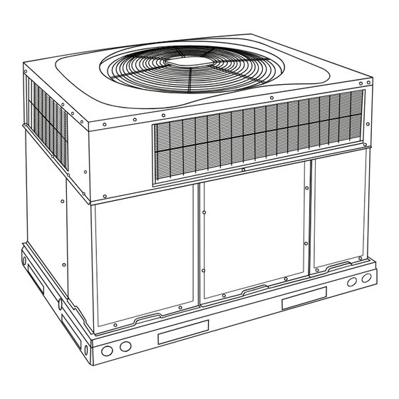
Fig. 1 - - Unit 48EZ- -A
. . . . . . . . . . . . . . . . . . . . . . . . . . . . . . . . . . .
. . . . . . . . . . . . . . . . . . . . . . . . . . .
. . . . . . . . . . . . . . . . . . . . . . . . . . . . . . . . . . . .
. . . . . . . . . . . . . . . . . . . . . . . . . . . . . .
. . . . . . . . . . . . . . . . . . . . . . . . . . . .
attached to the unit. Consult local
A09034
35
35
35
35
38
38
.
Advertisement
Table of Contents

Related Manuals for Carrier 48EZ(N)-A


Summary of Contents for Carrier 48EZ(N)-A
-
Page 1: Table Of Contents
48EZ(N) ---A Comfort t 13 SEER Single ---Packaged HYBRID HEATr Dual Fuel System with Puron® (R ---410A) Refrigerant Single and Three Phase 2---5 Nominal Tons (Sizes 24---60) Installation Instructions NOTE: Read the entire instruction manual before starting the installation. NOTE: Installer: Make sure the Owner’s Manual and Service Instructions are left with the unit after installation. -
Page 2: Introduction
es which may result in minor personal injury or product and prop- erty damage. NOTE is used to highlight suggestions which will result in enhanced installation, reliability, or operation. WARNING ELECTRICAL SHOCK HAZARD Failure to follow this warning could result in personal injury or death. - Page 3 A09450 Fig. 2 - - 48EZ- -A24- -36 Unit Dimensions...
- Page 4 A09451 Fig. 3 - - 48EZ- -A42- -60 Unit Dimensions...
- Page 5 HVAC unit HVAC unit basepan base rails Sealing Gasket Roofcurb Anchor screw Wood nailer* Flashing field supplied Roofcurb* Insulation (field supplied) Roofing material field supplied Cant strip field supplied *Provided with roofcurb A09090 ROOF CURB DETAIL LARGE CURB CATALOG UNIT SIZE NUMBER IN.
-
Page 6: Field Fabricate Ductwork
CAUTION - NOTICE TO RIGGERS PRUDENCE - AVIS AUX MANIPULATEUR ACCESS PANELS MUST BE IN PLACE WHEN RIGGING. PANNEAUX D'ACCES DOIT ÊTRE EN PLACE POUR MANIPULATION. Use top skid as spreader bar. / Utiliser la palette du haut comme barre de répartition SEE DETAIL A VOIR DÉTAIL A RIGGING WEIGHTS (SMALL CABINET) -
Page 7: Connect Condensate Drain
hooking points and load support areas. Materials showing any kind of wear in these areas must not be used and should be discarded. WARNING UNIT FALLING HAZARD Failure to follow this warning could result in personal injury or death. Never stand beneath rigged units or lift over people. WARNING PROPERTY DAMAGE HAZARD Failure to follow this warning could result in personal... -
Page 8: Fire Or Explosion Hazard
A 1/8- -in. (3.2 mm) NPT plugged tapping, accessible for test gauge connection, must be installed immediately upstream of the gas supply connection to the gas valve. When installing the gas supply line, observe local codes pertaining to gas pipe installations. Refer to the NFGC NFPA 54/ANSI Z223.1 latest edition (in Canada, CAN/CGA B149.1). -
Page 9: Install Duct Connections
Step 9 — Install Duct Connections The unit has duct flanges on the supply- - and return- -air openings on the side and bottom of the unit. For downshot applications, the ductwork connects to the roof curb (See Fig. 2 and 3 for connection sizes and locations). - Page 10 UNIT SIZE 48EZ --- A NOMINAL CAPACITY --- ton SHIPPING WEIGHT --- lb. (kg) COMPRESSORS Quantity REFRIGERANT (R --- 410A) Quantity --- lb (kg) REFRIGERANT METERING DEVICE OUTDOOR ORIFICE in. (qty) (mm) OUTDOOR COIL Rows...Fins/in. Face Area--- sq ft OUTDOOR FAN Nominal Cfm Diameter--- in.
-
Page 11: Manifold Pressure
UNIT SIZE 48EZ --- A NOMINAL CAPACITY --- ton OPERATING WEIGHT--- lb (kg) COMPRESSORS Quantity REFRIGERANT (R --- 410A) Quantity --- lb (kg ) REFRIGERANT METERING DEVICE OUTDOOR ORIFICE --- in. (qty) (mm) OUTDOOR COIL Rows...Fins --- in. Face Area--- sq ft OUTDOOR FAN Nominal Cfm Diameter--- in. -
Page 12: Install Electrical Connections
Step 10 — Install Electrical Connections WARNING ELECTRICAL SHOCK HAZARD Failure to follow this warning could result in personal injury or death. The unit cabinet must have an uninterrupted, unbroken electrical ground. This ground may consist of an electrical wire connected to the unit ground screw in the control compartment, or conduit approved for electrical ground when installed in accordance with NEC, NFPA 70 National Fire Protection Association (latest edition) (in Canada, Canadian... -
Page 13: Control Voltage Connections
Control Voltage Connections Do not use any type of power- -stealing thermostat. Unit control problems may result. Use no. 18 American Wire Gage (AWG) color- -coded, insulated (35_C minimum) wires to make the control voltage connections between the thermostat and the unit. If the thermostat is located more than 100 ft (30.5 m) from the unit (as measured along the control voltage wires), use no. -
Page 14: Pre- -Start- -Up
4. Verify the following conditions: a. Make sure gas line is free of air. Before lighting the unit for the first time, perform the following with the gas valve in the “OFF” position: NOTE: If the gas supply pipe was not purged before connecting the unit, it will be full of air. -
Page 15: Check Gas Input
integrated gas unit controller (IGC) has the capability to automatically reduce the evaporator “ON” delay and in- crease the evaporator “OFF” delay in the event of high duct static and/or partially- -clogged filter. Check Gas Input Check gas input and manifold pressure after unit start- -up (See Table 3). -
Page 16: Check Burner Flame
EXAMPLE: Assume that the size of test dial is 1 cu ft, one revolution takes 32 sec, and the heating value of the gas is 1050 Btu/ft . Proceed as follows: 1. 32 sec. to complete one revolution. 2. 3600 ÷ 32 = 112.5. 3. -
Page 17: Checking And Adjusting Refrigerant
placed in ON position and shuts down when FAN switch is placed in AUTO position. 2. Place SYSTEM switch in COOL position and FAN switch in AUTO position. Set cooling control below room temperature. Observe that compressor, condenser fan, and evaporator blower motors start. -
Page 18: Continuous Fan Operation
2. Remove the current speed tap wire from the “LOW” terminal on the interface fan board (IFB) (See Fig. 13) and place vinyl cap over the connector on the wire. 3. Connect the desired speed tap wire to the “LOW” terminal on the interface fan board (IFB). - Page 27 A10207C Fig. 14 - - 208/230- -1- -60 Connection Wiring Diagram, Unit 48EZ- -A...
- Page 28 A10207L Fig. 14 Cont - - 208/230- -1- -60 Ladder Wiring Diagram, Unit 48EZ- -A...
- Page 29 A10208C Fig. 15 - - 208/230- -3- -60 Connection Wiring Diagram, Unit 48EZ- -A...
- Page 30 A10208L Fig. 15 Cont. - - 208/230- -3- -60 Ladder Wiring Diagram, Unit 48EZ- -A...
- Page 31 A08019 Fig. 16 - - Cooling Charging Table- -Subcooling...
-
Page 32: Cut Hazard
MAINTENANCE To ensure continuing high performance and to minimize the possibility of premature equipment failure, periodic maintenance must be performed on this equipment. This combination heating/cooling unit should be inspected at least once each year by a qualified service person. To troubleshoot cooling or heating of units, refer to Tables 12, 13 and 14. -
Page 33: Flue Gas Passageways
f. Connect 5 pin plug and 4 pin plug to indoor blower motor. g. Reinstall blower access panel (see Fig. 18). 3. Restore electrical power to unit. Start unit and check for proper blower rotation and motor speeds during heating and cooling cycles. -
Page 34: Defrost Thermostat
BLOWER HOUSING 2 SETSCREWS (HIDDEN) Fig. 19 - - Removal of Motor and Blower Wheel Fig. 20 - - Burner Rack Removed FEEDER TUBE STUB TUBE DEFROST THERMOSTAT Fig. 21 - - Defrost Thermostat Location Fig. 22 - - Burner Rack Removed Outdoor Fan CAUTION UNIT OPERATION HAZARD... -
Page 35: Gas Input
Speedup Quiet Pins Shift WARNING EXPLOSION, PERSONAL INJURY ENVIRONMENTAL HAZARD Failure to follow this warning could result in personal injury, death or property damage. System under pressure. Relieve pressure and recover all refrigerant before system repair or final unit disposal. Use all service ports and open all flow- -control devices, including solenoid valves. -
Page 36: Explosion Hazard
2. Disconnect leads on switch. 3. Apply ohm meter leads across switch. You should have continuity on a good switch. NOTE: Because these switches are attached to refrigeration system under pressure, it is not advisable to remove this device for troubleshooting unless you are reasonably certain that a problem exists. -
Page 37: Outdoor Coil
HP S LEGEND HPS – High Pressure Switch LCS – Loss of Charge Switch Accurater Metering De vice ® Arrow indicates direction of flo w Fig. 25 - - Typical Heat Pump Operation, Cooling Mode HP S LEGEND HPS – High Pressure Switch LCS –... -
Page 38: Troubleshooting
Servicing Systems on Roofs and with Synthetic materials POE (polyolester) compressor lubricants are known to cause long term damage to some synthetic roofing materials. Exposure, even if immediately cleaned up, may cause embrittlement (leading to cracking) to occur in one year or more. When performing any service that may risk exposure of compressor oil to the roof, take appropriate precautions to protect roofing. - Page 39 Table 12 – Troubleshooting Guide - - Cooling or Heat Pump Heating Mode SYMPTOM CAUSE Power Failure Fuse blown or circuit breaker tripped Defective thermostat, contactor, transformer, or control Compressor and Outdoor fan will not relay start. Insufficient line voltage Incorrect or faulty wiring Thermostat setting too high Faulty wiring or loose connections in compressor circuit...
- Page 40 SYMPTOM Water in gas line No power to furnace No 24--v power supply to control circuit Burners will not ignite Mis--wired or loose connections Misaligned spark electrodes No gas at main burners Dirty air filter Gas input to furnace too low Unit undersized for application Inadequate heating Restricted airflow...
- Page 41 * Measured at suction inlet to compressor { Measured at liquid line leaving condenser. Copyright 2010 Carrier Corp. S 7310 W. Morris St. S Indianapolis, IN 46231 Manufacturer reserves the right to change, at any time, specifications and designs without notice and without obligations.
Need help?
Do you have a question about the 48EZ(N)-A and is the answer not in the manual?
Questions and answers