Advertisement
Table of Contents
- 1 Table of Contents
- 2 Introduction
- 3 Declaration of Conformity, Disposal and Recycling, CE Marking
- 4 Safety Notice and Precaution
- 5 Operating Instructions
- 6 Control Panel
- 7 Switch and Fuse
- 8 Modelling Light
- 9 Digital Power Display, Photo-Cell
- 10 Synchronisation, Wireless Remote Control and Flash Triggering
- 11 Acoustic Signal
- 12 DVD, «The Beginner's Guide to Light
- 13 Troubleshooting
- 14 Technical Data
- 15 Elinchrom Accessories
- 16 Guarantee
- Download this manual
Advertisement
Table of Contents

Subscribe to Our Youtube Channel
Related Manuals for Elinchrom Style FX 100


Summary of Contents for Elinchrom Style FX 100
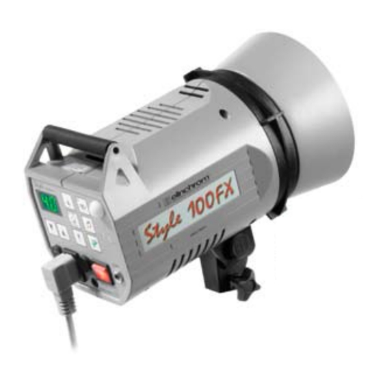
- Page 1 Operating Manual Style FX 100/400 English Elinca S.A Style FX 01.01.2007 ENG (73276) Printed in Switzerland 190/260V...
-
Page 2: Table Of Contents
Table of contents Introduction Declaration of conformity, disposal and recycling, CE marking Safety notice and precaution Operating instructions Control Panel Switch and Fuse Modelling Light Digital power display, Photo-cell Synchronisation, Wireless Remote control and flash triggering Acoustic signal DVD, «The beginner’s guide to light» Troubleshooting Technical Data Elinchrom Accessories... -
Page 3: Introduction
- Consult the dealer or an experienced radio/TV technician for help. ELINCA S.A. is not responsible for any radio or television interference caused by unauthorised modifications of this equipement or the substitution or attachment of connecting cables and equipement other than those specified by ELINCA S.A. -
Page 4: Declaration Of Conformity, Disposal And Recycling, Ce Marking
Phone : Fax: We, ELINCA S.A., hereby declare that the equipement bearing the trade name and model number specified above was tested conforming to the applicable FCC rules, and that all the necessary steps have been taken and are in force to assure that the production units of the same equipement will continue to comply with the Comissions requirements. -
Page 5: Safety Notice And Precaution
Safety notice According to safety regulations, we draw your attention to the fact that these electronic flash units are not designed for use outdoors, in damp or dusty conditions and should not be used after being exposed to sudden temperature changes causing condensation. They must always be connected to an earthed (grounded) mains supply. -
Page 6: Operating Instructions
Before you start ! The Style FX are adapted for operation on 190-260V/50-60Hz. Before connecting for the first time, check to make sure that your modelling lamp coincides with the voltage line. They must always be connected to an earthed ( grounded) mains supply. All Style FX units have a bayonet mount and locking ring reflector fitting, for fixing all Elinchrom and Prolinca accessories. -
Page 7: Control Panel
Control Panel Overview of controls 1.Mains inlet socket 2.Mains fuse (slow blow) 3.Mains Illuminated on/off switch 4.Modelling fuse (fast blow) 5.Open-flash 6.Synchro-sockets, Amphenol + jack 3.5 mm 7.Digital power display and charge/discharge indicator 8. Acoustic recharging signal (Beep) 9. Slave cell switch on/off 10. -
Page 8: Switch And Fuse
Mains Supply With the MAINS SWITCH (3) switched off ("O" position), firmly push in the plug of the original ELINCHROM mains cord into the mains socket (1). Mains Switch The switch should light up when the compact is switched on ("I" position). (Switch off before removing the mains cord). -
Page 9: Modelling Light
Modelling Light The touch pad (14) controls the modelling lamp on/off and the proportional light. Select the power with the touch pad (15). The modelling light output (100%) is achieved when the power value is set to maximum. Proportional modelling lamp, is set when the position "PROP" is selected (led is illuminated), the light output is proportional to the selected flash power. -
Page 10: Digital Power Display, Photo-Cell
Digital power display The actual flash power is shown in a f-stop compatible format. The power range is 5 f-stops. The digital display, provides continuous power indication of the flash and modelling lamp. The controls cover a continuous output range from full power 1/1 to 1/16th in 1/10th, f-stop intervals. -
Page 11: Synchronisation, Wireless Remote Control And Flash Triggering
Cordless flash control EL-Skyport triggers flashes without sync cords over a distance of approximately 100 m. Further detailed information please find under : www.elinchrom.com / Products / RX Multi Remote EL-Skyport Universal Set (19360) Sychronisation socket The standard socket 3.5 mm mini-jack (6). N.B. -
Page 12: Dvd, «The Beginner's Guide To Light
Troubleshooting 1. The mains switch (3) is ON ("I" position), but does not light up: • Switch OFF the unit and change the mains fuse (2) • Use only time-lag fuse (16 AT), corresponding to the Style FX model 2. The switch (3) is lit, the open flash ready is lighting up but does not function. •... -
Page 13: Technical Data
Features • Mains switch • Controls for: modelling on/off, cell on/off, acoustic signal on/off. • Flash and modelling power control. • «X» synchro jack socket 3,5 mm. • Socket for Plug-In remote control. • Mains inlet socket and two fuses (Mains and modelling). •... -
Page 14: Elinchrom Accessories
Elinchrom Accessories Reflectors Wide angle ø 16 cm /90° Compact ø 18 cm /60° Standard ø 21 cm /50° Mini soft ø 44 cm silver Mini soft ø 44 cm white Snoot & Grid Grid for snoot Grids Grid set for reflector 18 cm Grid set for 21 cm Filters Set of 10 color/mixed filters for 21 cm x 21 cm... -
Page 15: Guarantee
This guarantee is not valid for equipment which has been misused, dismantled, modified or repaired by persons not belonging to the ELINCA distribution network. It does not cover flash tubes, lamps and the normal ageing of capacitors. No responsibilities can be accepted for damage resulting from unsatisfactoıy operation of the equipment, such as wasted film or other expenses. - Page 16 www.elinchrom.com...
Need help?
Do you have a question about the Style FX 100 and is the answer not in the manual?
Questions and answers