Table of Contents
Advertisement
Quick Links
Advertisement
Table of Contents

Related Manuals for Laird OL 4503


Summary of Contents for Laird OL 4503
- Page 1 OL 4503 Oil-Air Cooling Unit Specification and User Manual Version 3.5...
- Page 2 Laird. All specifications are subject to change without notice. Laird assumes no responsibility and disclaims all liability for losses or damages resulting from use of or reliance on this information. All Laird products are sold subject to the Laird Terms and Conditions of sale (including Laird’s limited warranty) in effect from time to time, a copy of which will be furnished upon request.
-
Page 3: Table Of Contents
Table of Contents Revision History ............................ 5 About this Manual ......................... 6 1.1 Terms of Guarantee ........................6 1.2 Contact Information ........................7 Product Identification ........................8 2.1 Unit Specifications ......................... 8 2.2 Identification Plate ......................... 8 Safety Regulations ........................9 3.1 Hazard classes .......................... - Page 4 11.3 Storing the Unit ......................... 30 11.4 Disposal ............................ 30 11.5 Disposal of Operating Materials ....................31 11.6 Return of the unit to Laird Thermal Systems ................31 Wear Parts and Spare Parts ....................... 32 Addendum............................34 Performance Chart ..........................34 Flow Scheme ............................
-
Page 5: Revision History
A. Wolf p. 25, 34 07-Jun-19 Pump capacity changed O.Lundqvist p.16 04-Sep-20 Specs. for Shell Diala updated to S4 from S3 A.Olsson p.16 25-Feb-2021 Replaced 95205237.00 with 2066.00 A.Kim p. 34 Reformated manual to Laird Thermal 7-Jul-2021 M. Maria Systems Template... -
Page 6: About This Manual
This document is the English translation of the original Operation Manual in German language for the Oil-Air Cooling Unit OL 4503 (called unit in the following). It is based on German safety regulations. In your country other regulations may apply. -
Page 7: Contact Information
Name of contact at your address Product data as on identification plate: Type of unit, serial number and year of manufacture Company contact: Laird Thermal Systems Prumyslová 497 462 11 Liberec Czech Republic Post: Laird Thermal Systems GmbH... -
Page 8: Product Identification
2. Product Identification 2.1 Unit Specifications Manufacturer Laird Thermal Systems GmbH Type of product Oil-air cooler Type of unit OL 4503 Article number 1264.00 Table 1: Unit specifications 2.2 Identification Plate The identification plate is attached to the front side of the unit (see Fig. 1). -
Page 9: Safety Regulations
3. Safety Regulations 3.1 Hazard classes In this document safety instructions are using standardized representation and symbols. Depending on the probability of their incidence and the severances of consequences three hazard classes are used. DANGER Reference to direct danger for humans. Inobservance will lead to irreversible injuries or exitus. -
Page 10: Hints For Safe Operation
3.3 Hints for Safe Operation NOTE Conduct inspections on a regular time base! This will ensure that the appropriate measures will be carried out indeed. The unit is operational save. It was built according to the existing state of technology. Despite this the unit could cause hazards if it is used in a way it was not intended for ... -
Page 11: Environmental Issues
3.6 Environmental Issues Environmentally conscious and anticipatory behavior of staff avoids environmentally hazardous impacts. The following principles apply for environmentally conscious behavior: Environmentally hazardous substances must not get into the ground or the drains. They should be kept in appropriate containers. Environmentally hazardous substances must be fed to utilization or disposal according to ... -
Page 12: Guards
Fig. 3: Safety equipment Thermostat Flow control device (flow switch) Angle-type safety valve Inspection glass, level indicator 3.10 Guards Direct access to hazardous parts or areas of the unit is restricted by the unit cover. The cover may only be removed for the purpose of maintenance or repair works and shall be replaced prior to taking the unit back to operation. -
Page 13: Caution Labels
3.11 Caution Labels Danger spots on the unit are indicated corresponding to German safety regulation BGV A8 "Sicherheits- und Gesundheitsschutzkennzeichnung am Arbeitsplatz". Caution labels on the unit must be easily readable at all times. Illegible caution labels must be exchanged without delay. Fig. -
Page 14: Product Description
4.1 Intended Use The oil-air cooler OL 4503 is used for the cooling of an oil circuit. Oil circulates between the cooling unit and the device to be cooled. The oil is recooled by an air-cooled heat exchanger. The maximum cooling capacity depends on the ambient air temperature (see page 16). -
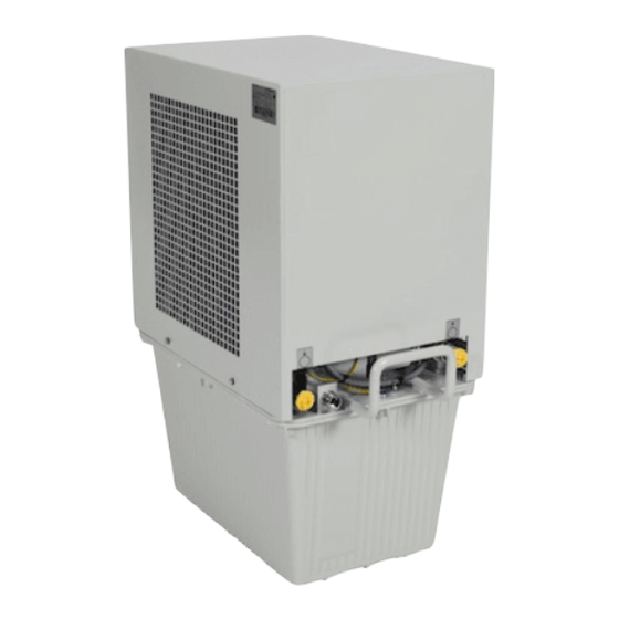
Page 15: Unit Components
4.3 Unit Components Additional information can be retrieved from the flow scheme shown in the addendum. The unit consists of the following main components: Fig. 6: Main components 1 Cooling circuit 2 Coolant container 3 Sheet-metal hood 4.4 Cooling Circuit In the cooling circuit the coolant (i.e. -
Page 16: Specifications
4.5 Specifications Dimensions and weight Length: 650 mm Width: 350 mm Height: 750 mm Weight: 49.6 kg (empty) Coolant capacity: 23 liters (Shell Diala S4-ZXIG) Table 4: Dimensions and weight Performance data Cooling capacity: 4500 Watts at 22.8 K difference between the oil outlet temperature and the ambient air temperature Pump capacity:... -
Page 17: Setting-Up Requirements
4.6 Setting-up Requirements Installation Location The location must be even. When choosing the installation location, the following must be kept in mind: the air flow of the cooling air must not be restricted, forward and back flow connections must be easily accessible and all tubes must be installed without sharp bends. -
Page 18: Transport
Lift the unit with a forklift or jack lift off the transportable pallet. Dispose of the packaging material in accordance with regional regulations. NOTE Laird Thermal Systems advises to keep the transportable pallet for later transportation of the unit. -
Page 19: Initial Operation
6. Initial Operation 6.1 Safety Indications Related to Initial Operation CAUTION Danger of malfunction caused by faulty connections during initial operation! Before switching on the unit make sure that All safety equipment of the unit is implemented and functional All connections were properly made ... -
Page 20: Cooling Circuit Connection And Filling
6.3 Cooling Circuit Connection and Filling CAUTION Risk of damage by using improper cooling hoses! This may lead to damage to persons, damage to the unit or corrosion damage. When choosing cooling hoses pay attention to sufficient burst strength and compatibility with ... - Page 21 Fig. 10: Operation cap, transportation cap, filler plug of coolant container 1 Operation cap 2 Transportation cap 3 Filler plug of coolant container Unscrew the four screws of the unit cover using a metric AF10 wrench and remove the cover. Remove the caps from the hose nipples of oil inlet and oil outlet.
-
Page 22: Electrical Connections
6.4 Electrical Connections DANGER Danger to life through electrical shock when working on the electrical equipment of the unit! Switch off the unit before starting your work! Disconnect the unit from mains by pulling the mains plug! Verify that the installation is dead (volt-free)! ... -
Page 23: Daily Start-Up
DANGER Danger to life by electrical shock caused by improperly mounted grounding washer! Mount the grounding washer at the position of one of the four screws securing the unit cover! Make sure that the screws are properly tightened! This is to make sure that the grounding washer cannot get loose by vibrations during operation which could lead to the situation of the unit cover carrying current. -
Page 24: Controlling The Unit
7. Controlling the Unit The unit is controlled using the controls of the equipment that is to be cooled. All alarm and error signaling is only indicated on the control panel of the equipment that is to be cooled. 7.1 Safety Indications for Controlling the Unit CAUTION Lack of coolant may destroy the pump! Operate the unit only when the oil filling indication on the coolant container is correct! -
Page 25: Settings
7.4 Settings The angle-type safety valve and the thermostat are set to the specified values by the manufacturer. Should any modification be required, please follow the steps indicated below. Fig 11: Angle-type safety valve Adjusting screw Hexagonal wrench key No 10 7.5 Pressure Setting on the Angle-type Safety Valve NOTE A small amount of oil may leak from the valve. -
Page 26: Setting The Thermostat
7.6 Setting the Thermostat Fig 12: Thermostat 1 Knob of thermostat Increase the temperature setpoint Turn the knob clockwise. The switch-off temperature is set to a higher value. Decrease the temperature setpoint Turn the knob counter-clockwise. The switch-off temperature is set to a lower value. ... -
Page 27: Disruptions
More help can be found in the following paragraph. In case you do not succeed in identifying the problem cause by means of this manual please contact the service department of Laird Thermal Systems. 8.2 Trouble Shooting For trouble shooting you may rely on the following: Alarm signaling within the safety circuit of the device to be cooled ... -
Page 28: Maintenance And Cleaning
9. Maintenance and Cleaning Diligent maintenance is the prime factor for assuring an error-free and efficient operation of the unit. Operating personnel can perform these tasks when properly trained. 9.1 Maintenance Schedule Device Activityt Interval Criteria Tools Performer Heat Exchanger Clean Minimum weekly Plate fins and... -
Page 29: Repair
10. Repair NOTE Do not carry out any repair work on the unit. Send the unit back to the LAIRD service department (for contact see page 7). -
Page 30: Dismounting, Disposal, Storage
Make sure the components of the unit end up at a qualified company for disposal and recycling. Contact Laird Thermal Systems for take back of end-of-life units (see company contact on page Error! Bookmark not defined.) or ask a company destined for disposal and recycling. -
Page 31: Disposal Of Operating Materials
Also, the safety specifications of the coolant manufacturer must be obeyed. 11.6 Return of the unit to Laird Thermal Systems NOTE Declaration of decontamination Before re-shipment of the unit a declaration of decontamination must be sent to Laird Thermal Systems. -
Page 32: Wear Parts And Spare Parts
Laird Thermal Systems parts are subject to strict obligations and fulfill these requirements. Laird Thermal Systems does not provide warranty service in case of damages caused by the use of spare parts made by manufacturers other than Laird Thermal Systems. - Page 33 Fig 14: Spare part overview part 2 Pos. Description Article No. Spare Pump 230V,50/60H,KA1-26-230-2 2066.00 Thermostat AMFS-13 95160001.00 Axial fan S4E 330-AP 18-31 95251655.00 Starter capacitor for fan 95290709.00 Starter capacitor for pump 95290735.00 Stop valve ¼“ 96521001.00 Angle-type safety valve 387002608 Inspection glass 93300201.00...
-
Page 34: Addendum
Addendum Performance Chart Leistung (KW) Cooling capacity versus difference between entering air and supplied coolant temperatures... -
Page 35: Flow Scheme
Flow Scheme... -
Page 36: Wiring Diagram
Wiring Diagram...
Need help?
Do you have a question about the OL 4503 and is the answer not in the manual?
Questions and answers
Hello I have a Cooling system that we use for our xray tube. We have just replaced the cooling system and we are getting the same error code we were receiving on the old one telling us that there is a cooling system failure. When we hooked up the new system it ran for about 5hours then gave us the cooling system failure again.
The cooling system failure error code on the Laird OL 4503 after replacing the cooling system could be caused by:
1. Coolant hoses not connected correctly or not considering flow direction.
2. Air blockages or sharply bent external hoses restricting flow.
3. Insufficient coolant due to evaporation; the coolant level should be checked and refilled if needed.
4. Heat exchanger pollution reducing cooling capacity; it may need cleaning.
5. Improper placement of the unit, such as inadequate clearance to walls.
6. Use of damaged or incompatible cooling hoses.
Check each of these points to identify and correct the issue.
This answer is automatically generated