Table of Contents
Advertisement
Advertisement
Table of Contents

Related Manuals for Rugged Radios GMR45


Summary of Contents for Rugged Radios GMR45
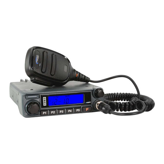
- Page 1 GMR45 USER MANUAL...
- Page 2 Federal Communications Commission (FCC) license. You must be licensed prior to operating on channels 1-7, 15-22 or RP15-22 which comprise the GMRS channels of the GMR45. Serious penalties may result from unlicensed use of GMRS channels, in violation of FCC rules, as stipulated in the Communications Act’s Sections 501 and 502 (amended).
-
Page 3: Table Of Contents
CONTENTS User Safety Information Standard GMRS Channels Package Includes GMRS Repeater Channels Main Features Specifications Initial Installation General Mobile Installation Receiver DC Power Cable Connection Transmitter Notes Replacing Fuses Antenna Connection Installing the Antenna Accessory Connections 5-Pin Cable External Speaker Getting Acquainted Front Panel Operation Rear Panel Operation... -
Page 4: User Safety Information
USER SAFETY INFORMATION • Do not attempt to configure your radio while driving. • This radio is designed for a 13.8V DC power supply. Do not use a 24V battery to power on the radio. • Do not place the transceiver in excessively dusty, humid or wet areas, nor unstable surfaces. -
Page 5: Package Includes
PACKAGE INCLUDES • Radio unit x 1 • Hand Mic x 1 • Mobile mounting bracket x 1 • DC power cable with fuse holder x 1 • Screw packs x 1 • Protection fuses x 1... -
Page 6: Main Features
Easily connect to intercom, headset, or any 5-pin accessory with the built-in Rugged Ready pigtail cable! Loaded with channels and features, the GMR45 is ideal for installation into your vehicle or setup at base camp. -
Page 7: Initial Installation
INITIAL INSTALLATION MOBILE INSTALLATION Mobile Installation: To install the radio select a safe and convenient location inside your vehicle that minimizes danger to your passengers and yourself while the vehicle is in motion. Consider installing the unit at an appropriate position so that knees or legs will not strike it during sudden braking of your vehicle. - Page 8 INITIAL INSTALLATION MOBILE INSTALLATION (CONT.) Position the radio, then insert and tighten the supplied hex/Phillips screws. Determine the appropriate angle of the radio using the 3 screw hole positions on the side of the mounting bracket. • Double check that all screws are tightened to prevent vehicle vibration from loosening the bracket or radio. •...
-
Page 9: Dc Power Cable Connection
INITIAL INSTALLATION DC POWER CABLE CONNECTION The vehicle battery must have a nominal rating of 12V. Never connect the radio to a 24V battery. Be sure to use a 12V vehicle battery that has sufficient current capacity. If the current to the radio is insufficient the display may darken during transmission or transmitting output power may drop dramatically. - Page 10 INITIAL INSTALLATION DC POWER CABLE CONNECTION (CONT.) Connect the DC power cable to the radio’s power supply connector. Press the connectors firmly together until the locking tab clicks.
-
Page 11: Replacing Fuses
If the fuse blows, determine the cause then correct the problem. After the problem is resolved replace the fuse. If newly installed fuses continue to blow, disconnect the power cable and contact Rugged Radios for assistance. Only use fuses of the specified type and rating otherwise the radio could be damaged. -
Page 12: Antenna Connection
ANTENNA CONNECTION Before operating, install an efficient well-tuned antenna. The success of your installation will depend largely on the type of antenna and its correct installation. The radio can give excellent results if the antenna system and its installation are given careful attention. Use a 50Ω... -
Page 13: Installing The Antenna
INSTALLING THE ANTENNA For the best range, only the Rugged Radios GMRS POINT5 antenna should be used. Specific installation requirements vary between vehicles. Use the following guidelines to install the antenna. Where you locate your antenna does make a difference! Avoid metal surfaces covered by fiberglass or vinyl that may affect radio range. -
Page 14: Accessory Connections
ACCESSORY CONNECTIONS 5-PIN CABLE With its 5-pin interface cable, the GMR45 is Rugged Ready and can be easily connected to headsets, intercoms, and other communication equipment. -
Page 15: External Speaker
ACCESSORY CONNECTIONS EXTERNAL SPEAKERS If you plan to use an external speaker, choose a speaker with an impedance of 8Ω. The external speaker jack accepts a 3.5mm mono (2-conductor) plug. When an external speaker is connected, the radios internal speaker is automatically disabled. EX-SPK-X... -
Page 16: Getting Acquainted
GETTING ACQUAINTED FRONT PANEL OPERATION... -
Page 17: Rear Panel Operation
GETTING ACQUAINTED REAR PANEL OPERATION Port Function Antenna Connector Connection for 50Ω antenna. Ext. Speaker Terminal Terminal for optional external speaker.. Ext. Power Jack Terminal for connecting optional cable for use with ignition key On/Off function. The radio will auto power on when car is driving. The radio will auto power off when car stops. -
Page 18: Display
GETTING ACQUAINTED DISPLAY... -
Page 19: Microphone
GETTING ACQUAINTED MICROPHONE Icon Function Hold microphone approximately 4 inches from mouth, press the key [#1], and speak into microphone. -
Page 20: Additional Features
GETTING ACQUAINTED ADDITIONAL FEATURES Feature Function In channel mode, this function is designed to monitor signal in every channel. Channel Scan 1. In channel mode, press P3 key for 1s to enter into channel scan 2. Turn selector knob key to change scan direction. 3. -
Page 21: Troubleshooting
TROUBLESHOOTING Problem Possible Cause and Potential Solutions + and - polarities of power connection are reversed. (a) Power is on, nothing appears Connect red lead to plus terminal and black lead to on Display. minus terminal of DC power supply. Check and solve problem resulting in blown fuse (b) Fuse is blown. -
Page 22: Tone Codes
TONE CODES CHANGING TONE CODES Press [F] + [P5] to get to the desired tone type: “T”, “T SQ”, “DCS”, or “SQ DCS”. “T” and “DCS” are transmit side only. “T SQ” and “SQ DCS” are transmit and receive. Use the channel knob to change tone codes. -
Page 23: Ctcss
GMRS TONE CODES CTCSS Analog Tone Codes This is the Freq. Freq. (Hz) (Hz) number you toggle to on 67.0 167.9 71.9 173.8 your r adio! 74.4 179.9 77.0 186.2 79.7 192.8 82.5 203.5 85.4 210.7 88.5 218.1 91.5 225.7 94.8 233.6 97.4... -
Page 24: Dcs
GMRS TONE CODES DCS Digital Tone Codes DCS (Digital) DCS (Digital) DCS (Digital) DCS (Digital) Code Code Code Code Codes 84-104 may not be supported by other br and GMRS r adios To toggle between numbered tone codes [EX: 22] and actual tone codes [EX:141.3], press [ ] when in tone code menu Only radios produced after March 1, 2022 (signified by a waterproof power connector) are equipped with this feature. -
Page 25: Standard Gmrs Channels
STANDARD GMRS CHANNELS Channel Frequency (MHz) 462.5625 462.5875 462.6125 462.6375 462.6625 462.6875 462.7125 467.5625 467.5875 467.6125 467.6375 467.6625 467.6625 467.7125 462.5500 462.5750 462.6000 462.6250 462.6500 462.6750 462.7000 462.7250... -
Page 26: Gmrs Repeater Channels
GMRS REPEATER CHANNELS Transmit Receive Channel Frequency (MHz) Frequency (MHz) 467.5500 462.5500 15RP 16RP 467.5750 462.5750 17RP 467.6000 462.6000 18RP 467.6250 462.6250 19RP 467.6500 462.6500 20RP 467.6750 462.6750 21RP 467.7000 462.7000 22RP 467.7250 462.7250... -
Page 27: Specifications
SPECIFICATIONS GENERAL Frequency GMRS Frequency stability ±2.5ppm Operating temperature -20°C ~ +60°C Operating voltage 13.8V DC Dimension 145x47x190mm RECEIVER Wide Band Narrow Band Sensitivity 0.25μV 0.35μV Intermodulation ≥65dB ≥60dB Spurious rejection ≥70dB ≥70dB Audio response +1~-3dB (0.3~3KHz) +1~-3dB (0.3~2.55KHz) Audio distortion <5% <5% FM hum and noise... -
Page 28: Transmitter
SPECIFICATIONS TRANSMITTER Wide Band Narrow Band Maximum Output power Modulation 16K Φ F3E 11K Φ F3E Adjacent Channel Power ≥70dB ≥60dB FM modulation ≥40dB ≥36dB Spurious Emission ≥60dB ≥60dB Audio Response + 1 ~ -3dB(0.3 ~ 3KHz) + 1 ~ -3dB(0.3 ~ 2.55KHz) Audio Distortion ≤... -
Page 29: Notes
NOTES... - Page 30 WWW.RUGGEDRADIOS.COM...
Need help?
Do you have a question about the GMR45 and is the answer not in the manual?
Questions and answers