Advertisement
Quick Links
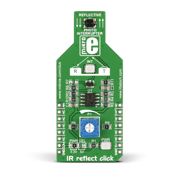
IR reflect
click
™
1. Introduction
IR reflect click
™
carries a GP2S700HCP
reflective photointerrupter. On this type of
photointerrupter the infrared emitter and
receiver are facing the same direction; the
infrared beam from the emitter gets bounced
back to the receiver when an object is placed
within the detecting range of the sensor
(Optimal Sensing Distance is 3mm). IR reflect
click
communicates with the target board
™
microcontroller through mikroBUS
AN and
™
INT pins (an onboard potentiometer sets
the Interrupt threshold). It's designed to use
either a 3.3V (by default) or 5V power supply.
2. Soldering the headers
Before using your click
™
board, make sure
to solder 1x8 male headers to both left and
right side of the board. Two 1x8 male headers
are included with the board in the package.
2
Turn the board upside down so that
the bottom side is facing you upwards.
Place shorter pins of the header into the
appropriate soldering pads.
1
3
Turn the board upward again. Make sure
to align the headers so that they are
perpendicular to the board, then solder the
pins carefully.
3. Plugging the board in
Once you have soldered the headers your
board is ready to be placed into the desired
mikroBUS
socket. Make sure to align the
™
cut in the lower-right part of the board with
the markings on the silkscreen at the
mikroBUS
socket. If all the
™
pins are aligned correctly,
push the board all the way
into the socket.
4. Essential features
These sensors are used to detect an object's
presence or motion, such as a piece of paper
passing through a printer. To avoid setting
off false alarms, avoid exposing the sensor
to other sources of infrared light (which
could come from an ordinary incandescent
light bulb). Also, black objects won't reflect
infrared so the click
™
won't detect them. On
the other hand, reflective metalic surfaces will
trigger the sensor from a larger range.
click
™
BOARD
www.mikroe.com
IR reflect click
™
manual
ver 1.02
0 1 0 0 0 0 0 0 7 7 2 9 0
Advertisement

Subscribe to Our Youtube Channel
Related Manuals for mikroElektronika click BOARD IR reflect click


Summary of Contents for mikroElektronika click BOARD IR reflect click
- Page 1 2. Soldering the headers Before using your click ™ board, make sure to solder 1x8 male headers to both left and right side of the board. Two 1x8 male headers are included with the board in the package. IR reflect click ™...
- Page 2 9. Support DETECTING OBJECT SURFACE 1IN- 2OUT LM2903 1IN+ 2IN- 2IN+ LM2903 MikroElektronika offers free tech support EMITTER ANODE (www.mikroe.com/support) until the end of MISO the product’s lifetime, so if something goes MOSI 2.2uF +3.3V wrong, we’re ready and willing to help!
Need help?
Do you have a question about the click BOARD IR reflect click and is the answer not in the manual?
Questions and answers