LG RD-JT91 Service Manual
Chassis : re-048a
Hide thumbs
Also See for RD-JT91:
- Owner's manual (28 pages) ,
- Service manual (34 pages) ,
- Owner's manual (31 pages)
Table of Contents
Advertisement
Quick Links
Advertisement
Table of Contents

Related Manuals for LG RD-JT91


Summary of Contents for LG RD-JT91
- Page 1 All manuals and user guides at all-guides.com website:http://biz.LGservice.com e-mail:http://www.LGEservice.com/techsup.html DLP PROJECTOR SERVICE MANUAL CHASSIS : RE-048A MODEL : RD-JT91 CAUTION BEFORE SERVICING THE CHASSIS, READ THE SAFETY PRECAUTIONS IN THIS MANUAL.
-
Page 2: Table Of Contents
All manuals and user guides at all-guides.com CONTENTS CONTENTS ........................2 SAFETY PRECAUTIONS ....................3 SERVICING PRECAUTIONS....................4 CONTROL DESCRIPTIONS .....................6 REPLACING OF LAMP ....................10 SPECIFICATIONS ......................11 ADJUSTMENT INSTRUCTION..................13 PRINTED CIRCUIT BOARD ...................18 BLOCK DIAGRAM......................21 EXPLODED VIEW......................22 EXPLODED VIEW PARTS LIST ..................23 REPLACEMENT PARTS LIST..................24 SVC. -
Page 3: Safety Precautions
All manuals and user guides at all-guides.com SAFETY PRECAUTIONS IMPORTANT SAFETY NOTICE Many electrical and mechanical parts in this chassis have special safety-related characteristics. These parts are identified by the Schematic Diagram and Replacement Parts List. It is essential that these special safety parts should be replaced with the same components as recommended in this manual to prevent X-RADIATION, Shock, Fire, or other Hazards. -
Page 4: Servicing Precautions
All manuals and user guides at all-guides.com SERVICING PRECAUTIONS CAUTION: Before servicing receivers covered by this service transistors and semiconductor "chip" components. The manual and its supplements and addenda, read and follow the following techniques should be used to help reduce the SAFETY PRECAUTIONS on page 3 of this publication. - Page 5 All manuals and user guides at all-guides.com c. Quickly move the soldering iron tip to the junction of the Fuse and Conventional Resistor component lead and the printed circuit foil, and hold it Removal/Replacement there only until the solder flows onto and around both the 1.
-
Page 6: Control Descriptions
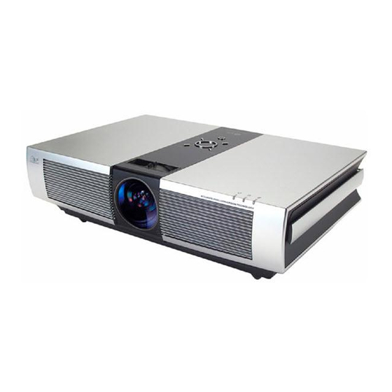
All manuals and user guides at all-guides.com CONTROL DESCRIPTIONS Names of parts Main Body * The projector is manufactured using high-precision technology. You may, however, see on the Projector screen tiny black points and/or bright points (red, blue, or green). This can be a normal result of the manufacturing process and does not always indicate a malfunction. - Page 7 All manuals and user guides at all-guides.com Control Panel , KEYSTONE+/- Button MENU SOURCE KEYSTONE MENU Button SOURCE Button Selects or closes menus. Switches to RGB, DVI, Video,S-Video mode. VOLUME Button Adjusts volume level and functions of menus. AUTO Button OK Button KEYSTONE Checks present mode and...
- Page 8 All manuals and user guides at all-guides.com Remote Control POWER POWER Button MENU KEYSTONE SOURCE SOURCE Button MENU Button KEYSTONE+/-, Button VOL-/+, Button AUTO Button OK Button AUTO KEYSTONE ARC Button BLANK Button BLANK STILL Button MUTE Button *Switches the sound on or off. STILL MUTE - 8 -...
- Page 9 All manuals and user guides at all-guides.com Projector Status Indicators * Lamp Indicator, operation indicator and temperature indicator at the top of the projector show the user the operating status of the projector. Lamp Indicator Operation Indicator Temperature Indicator Orange Standby.
-
Page 10: Replacing Of Lamp
All manuals and user guides at all-guides.com REPLACING OF LAMP The projector lamp should lasts for about 2000 hours.You can see the lamp hours time in the selecting function section.You 4. After lifting the lamp cover off, remove the two retaining must replace the lamp when one or more of the following screws on the lamp case with a screwdriver. -
Page 11: Specifications
6) Warm up TV set for more than 30min. before the measurement. Test and Inspection Method 1) performance:Follow the Standard of LG TV test 2) RCA JACK performance: Follow the standard of LG 3) Standards of Etc requirement SAFETY:CE (EN55020), Electric wave:CB (EN55013) - Page 12 All manuals and user guides at all-guides.com Feature and function Specification Item Remark Unit REMOCON NEC Code DVI Input Digital RGB DVI-D RGB Input Separate D-Sub 15 pin Component input Y, P D-Sub 15 pin 480i, 480p, 720p, 1080i, 576i,576p Composite input 480i, 576i RCA jack(Yellow)
-
Page 13: Adjustment Instruction
All manuals and user guides at all-guides.com ADJUSTMENT INSTRUCTION 1. Application Object 4. Folding Mirror Adjustment This instruction is for the application to the DLP Projector 4-1. Before adjusting, check the position of (CHASSIS : RE-048A). Folding MIrror 2. Notes Check the position of Folding Mirror in the base of up / down / left / right surface. - Page 14 All manuals and user guides at all-guides.com 4-2. Illuminator Adjustment Sequence (4) Final Adjustment Repeat turn screw (C) up / down adjustment to the right / left Check the full white screen refer to (Fig 4-3) and make and mark where the image is aligned. Fix the adjustment adjustments in the following sequence.
- Page 15 All manuals and user guides at all-guides.com 4-3. Illuminator Phenomenon Adjustment Illuminator goes down direction Illuminator goes down area Screen state Adjustmen Screw Description t part direction Initial state State after adjusting At first, upside illuminator goes down Right and right illuminator also goes down in (tighten direction) detail.
- Page 16 All manuals and user guides at all-guides.com 6. RGB Offset/Gain Adjustment 7. COMPONENT Offset/Gain Adjustment (1) Select 75% color bar of <Fig. 7> for PC Pattern Generator 6-1. Required Test Equipment pattern. (Resolution 480p) (1) Pattern Generator 1EA (For analog RGB) (2) Remote control 1EA 6-2.
- Page 17 All manuals and user guides at all-guides.com 8-3. Preparation for Adjustment (4) Press the Instart key on the service remote control to select White balance. (1) Connect the power cord and turn the set on, then connect (5) Change X, Y as below seeing X and Y coordinate of it to a PC input.
-
Page 18: Printed Circuit Board
All manuals and user guides at all-guides.com PRINTED CIRCUIT BOARD MAIN(TOP) - 18 -... - Page 19 All manuals and user guides at all-guides.com MAIN(BOTTOM) - 19 -...
- Page 20 All manuals and user guides at all-guides.com DMD(TOP) DMD(BOTTOM) - 20 -...
-
Page 21: Block Diagram
All manuals and user guides at all-guides.com BLOCK DIAGRAM - 21 -... -
Page 22: Exploded View
All manuals and user guides at all-guides.com EXPLODED VIEW IC753 - 22 -... -
Page 23: Exploded View Parts List
SHEET (MECH), PVC MAIN . SHIELD 4980V01097D SUPPORTER, PCB MSWR RD-JT91 3501V00196C POWER SUPPLY ASSEMBLY, POWER RD-JT91 RE048A PV-JT91 POWER VALLEY SMPS BOARD 100_240V . POWERVALLEY . 4980V01097C SUPPORTER, PCB MSWR RD-JT91 3501V00196E POWER SUPPLY ASSEMBLY, POWER RD-JT91 RE048A POWER VALLEY PFC BOARD 100_240V . POWERVALLEY . -
Page 24: Replacement Parts List
All manuals and user guides at all-guides.com REPLACEMENT PARTS LIST LOCA. NO PART NO DESCRIPTION LOCA. NO PART NO DESCRIPTION 0TR387500AA Q103 CHIP 2SC3875S(ALY) KEC Q104 0TR222209AB KTN2222AS NPN MMBT2222A TP KEC - - D170 0IMCRSH003A GP2S40 SHARP 4P DIP ST PHOTOINTERRUPTER Q105 0TRKE80040A KTN2907AS(ZH) KEC R/TP SOT23 -5V -600MA... - Page 25 All manuals and user guides at all-guides.com For Capacitor & Resistors, CC, CX, CK, CN : Ceramic RD : Carbon Film the charactors at 2nd and 3rd CQ : Polyestor RS : Metal Oxide Film digit in the P/No. means as CE : Electrolytic RN : Metal Film follows;...
- Page 26 All manuals and user guides at all-guides.com For Capacitor & Resistors, CC, CX, CK, CN : Ceramic RD : Carbon Film the charactors at 2nd and 3rd CQ : Polyestor RS : Metal Oxide Film digit in the P/No. means as CE : Electrolytic RN : Metal Film follows;...
- Page 27 All manuals and user guides at all-guides.com For Capacitor & Resistors, CC, CX, CK, CN : Ceramic RD : Carbon Film the charactors at 2nd and 3rd CQ : Polyestor RS : Metal Oxide Film digit in the P/No. means as CE : Electrolytic RN : Metal Film follows;...
- Page 28 All manuals and user guides at all-guides.com For Capacitor & Resistors, CC, CX, CK, CN : Ceramic RD : Carbon Film the charactors at 2nd and 3rd CQ : Polyestor RS : Metal Oxide Film digit in the P/No. means as CE : Electrolytic RN : Metal Film follows;...
- Page 29 DESCRIPTION LOCA. NO PART NO DESCRIPTION COIL ACCESSORIES L101 6140VB0028A COIL,CHOKE SP5845-680 GET 68UH SMD 3828VA0482B MANUAL,OWNERSRE048A RD-JT91/2 LG EN, 373-026H L102 6140VB0028A COIL,CHOKE SP5845-680 GET 68UH SMD 6710V00133A REMOTE CONTROLLERRE03RA RD-JT91 L103 6140VB0028A COIL,CHOKE SP5845-680 GET 68UH SMD 6410VOH001A...
- Page 30 All manuals and user guides at all-guides.com...
- Page 31 All manuals and user guides at all-guides.com...
- Page 32 All manuals and user guides at all-guides.com...
- Page 33 All manuals and user guides at all-guides.com...
- Page 34 All manuals and user guides at all-guides.com Jun., 2004 P/NO : 3828VD0085Q Printed in Korea...
Need help?
Do you have a question about the RD-JT91 and is the answer not in the manual?
Questions and answers