Table of Contents

Related Manuals for Helmer UltraCW

Summary of Contents for Helmer UltraCW
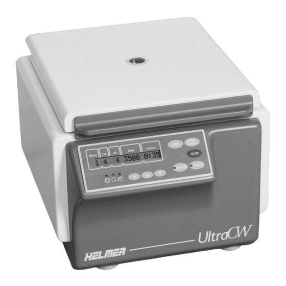
- Page 1 Automatic Cell Washing System Service Manual UltraCW™ Version B Model UltraCW™ HELMER, INC. 15425 HERRIMAN BLVD., NOBLESVILLE, IN 46060 USA PHONE (317) 773-9073 FAX (317) 773-9082 USA and CANADA (800) 743-5637 www.helmerinc.com 360113-1/A...
-
Page 2: Table Of Contents
Contents Contents About this manual ............ii 1 Working safely . -
Page 3: About This Manual
UltraCW™ Automatic Cell Washing System Service Manual About this manual Welcome to the UltraCW™ Automatic Cell Washing System Service Manual. This section explains the symbols and conventions used in this manual, copyright information about this document, and trademark information for products supplied by Helmer. -
Page 4: Working Safely
Working safely Working safely This section describes general safety information for servicing the UltraCW Automatic Cell Washing System (“cell washer”). The Operation Manual includes additional safety information for operating and cleaning the cell washer. Your organization may provide additional safety information. -
Page 5: Reviewing Information About Your Cell Washer
UltraCW™ Automatic Cell Washing System Service Manual Reviewing information about your cell washer This section explains how to find identification information about your cell washer. Finding model and input power information The Product Specification label is located on the right side of the cell washer next to the power connector. -
Page 6: Troubleshooting
Troubleshooting Troubleshooting Before taking actions as described in this section, make sure that operational issues have been addressed as described in the Operation Manual. Also, be sure that the cell washer operator has followed the appropriate laboratory procedures and used the appropriate materials for the task. This section describes some problems you may experience, explains possible causes, and provides actions you can take to correct them. -
Page 7: Addressing Error Messages
UltraCW™ Automatic Cell Washing System Service Manual Problem Possible Cause Action The rotor speed seems to A part in the speed Measure the rotor speed. For instructions, see be too high or too low. sensor circuit is faulty. Section 4.1, “Testing whether the rotor speed is within the design tolerance.”... - Page 8 Troubleshooting Error Possible cause Action message number Continued A part in the lid lock circuit is faulty. Clear the error message: Open the lid, then turn off the power. After about 10 seconds, turn 06 to 09 the power back on. Try the following tasks in order, testing after each to determine if it solved the problem: Replace the ribbon cable between the...
- Page 9 UltraCW™ Automatic Cell Washing System Service Manual Error Possible cause Action message number The main supply voltage is too low, Clear the error message: Open the lid, then resulting in an undervoltage condition turn off the power. After about 1 minute, turn to the frequency converter.
- Page 10 Troubleshooting Error Possible cause Action message number A part in the frequency converter Clear the error message: Open the lid, then circuit is faulty, resulting in an turn off the power. After about 1 minute, turn overtemperature condition in the the power back on.
- Page 11 UltraCW™ Automatic Cell Washing System Service Manual Error Possible cause Action message number A part in the frequency converter Clear the error message: Open the lid, then circuit is faulty, resulting in a turn off the power. After about 10 seconds, turn processing error.
- Page 12 Troubleshooting Error Possible cause Action message number Continued A part in the imbalance microswitch Clear the error message: Open the lid, then None circuit is faulty turn off the power. After about 10 seconds, turn the power back on. Try the following tasks in order, testing after each to determine if it solved the problem: Check the continuity of the imbalance microswitch, which is normally closed.
- Page 13 UltraCW™ Automatic Cell Washing System Service Manual N > MAX XX When this message appears, the rotor speed being detected exceeds the maximum allowable speed. Error Possible cause Action message number The insulation on the speed sensor Clear the error message: Turn off the power.
- Page 14 Troubleshooting N < MIN XX When this message appears, the rotor is rotating too slowly. Error Possible cause Action message number A connection in the motor circuit is Clear the error message: Open the lid, then loose. turn off the power. After about 10 seconds, turn the power back on.
- Page 15 UltraCW™ Automatic Cell Washing System Service Manual SER I/O - ERROR XX When a message of this type appears, there is a problem with communication between components. Error Possible cause Action message number 30 and 31 A connection in the frequency Clear the error message: Turn off the power.
- Page 16 Troubleshooting TACHO - ERROR XX When a message of this type appears, the rotor is not installed, or the speed is being controlled or sensed incorrectly. Message Possible cause Action number A connection in the speed sensor Clear the error message by doing the circuit is loose, resulting in the following: interruption of speed sensor pulses.
- Page 17 UltraCW™ Automatic Cell Washing System Service Manual Message Possible cause Action number A connection in the speed sensor and Clear the error message by doing the motor circuit is loose, resulting in no following: speed sensor pulses after start-up. Open the lid, then turn off the power.
-
Page 18: Servicing The Cell Washer
Servicing the cell washer Servicing the cell washer This section explains how to access serviceable parts, as well as how to perform some service procedures. Testing whether the rotor speed is within the design tolerance NOTE: You cannot test the decant speed, but you can change it by changing a global parameter value. -
Page 19: Testing Whether The Imbalance Value Is In The Permissible Range
UltraCW™ Automatic Cell Washing System Service Manual Testing whether the imbalance value is in the permissible range The imbalance microswitch senses whether the rotor is balanced during operation. If the rotor is not balanced, an imbalance error results. The weight at which the imbalance error occurs is the imbalance value. -
Page 20: Adjusting The Imbalance Microswitch
Servicing the cell washer Adjusting the imbalance microswitch For more information about locating and identifying parts, see Section 5, “Parts” NOTE: and Section 6, “Schematic.” The imbalance microswitch senses whether the rotor is balanced during operation. If the rotor is not balanced, an imbalance error results. -
Page 21: Removing And Installing The Front Panel
UltraCW™ Automatic Cell Washing System Service Manual Removing and installing the front panel For more information about locating and identifying parts, see Section 5, “Parts” NOTE: and Section 6, “Schematic.” Several serviceable parts are located behind the front panel. This section explains how to access them. -
Page 22: Adjusting The Display Contrast
Servicing the cell washer Adjusting the display contrast For more information about locating and identifying parts, see Section 5, “Parts” NOTE: and Section 6, “Schematic.” You will need the following to adjust the display contrast: ► Small flathead screwdriver with insulated shank Control/display board with detail of the trimming potentiometer To adjust the display contrast Remove the rotor from the cell washer, and leave the lid open. -
Page 23: Viewing And Changing The Fill Speed
UltraCW™ Automatic Cell Washing System Service Manual 4.6 Viewing and changing the fill speed You can change the value for the Fill (rpm) parameter, which is used to control the rotor speed during Fill and Suspension steps in non-cleaning processes. The Fill (rpm) parameter is factory preset to 1100 r/min for use in cell washing processes. This parameter should only be changed if the cell washer is being used for other applications that may require a different fill speed. -
Page 24: Replacing The Frequency Converter
Servicing the cell washer Replacing the frequency converter For more information about locating and identifying parts, see Section 5, “Parts” NOTE: and Section 6, “Schematic.” The frequency converter generates and monitors the current supply for the drive motor. It also monitors the motor temperature and transfers the electrical energy produced during braking to the braking resistor. -
Page 25: Setting Jumpers
UltraCW™ Automatic Cell Washing System Service Manual 4.7.1 Setting jumpers The jumper settings on the control/display board must be changed to enter initialization mode. Jumper settings. Left: Normal operating mode. Right: Initialization mode. The control/display board has one jumper installed. To set the jumpers for initialization mode, you will need a second standard 2-pin jumper. -
Page 26: Removing And Installing The Bowl Assembly
Servicing the cell washer Removing and installing the bowl assembly For more information about locating and identifying parts, see Section 5, “Parts” NOTE: and Section 6, “Schematic.” You will need the following to remove or install the bowl assembly: ► Small flathead screwdriver ► Allen wrenches in the following sizes: 2 mm, 2.5 mm, 4 mm, and 5 mm. - Page 27 UltraCW™ Automatic Cell Washing System Service Manual Working your way around the hole in the bowl, gently pull the silicone motor seal toward the motor shaft. Lift the gasket, drainage rings, and bowl assembly from the housing, tilting the bowl so that the drain connector clears the housing.
-
Page 28: Performing Post-Repair Checks
Servicing the cell washer Performing post-repair checks Perform functional and safety checks of the cell washer after repairing or replacing parts. For more information and instructions to program and use the cell washer, refer to the Operation Manual. To perform a functional check NOTE: Regulations for your organization may recommend test methods different from what appear here. -
Page 29: Parts
UltraCW™ Automatic Cell Washing System Service Manual Parts The Troubleshooting section recommends replacing parts in certain situations. This section shows where to find replaceable parts and lists part numbers for them. It also includes references to the parts on the electrical schematic, as appropriate. -
Page 30: Parts On The Rear And Bottom
Parts Parts on the rear and bottom Parts on the rear and bottom of the cell washer Label Description Replacement part numbers Label on schematic Rear panel E2107 Drain connector Part of Bowl assembly (E2104-A), which includes the bowl Supply connector Part of Flow meter (E2103) Foot 3680 Parts on the side A B C Parts on the right side of the cell washer Label... -
Page 31: Parts On The Bowl And Rotor
UltraCW™ Automatic Cell Washing System Service Manual Parts on the bowl and rotor Parts on the bowl and rotor Label Description Replacement part numbers Drainage rings Part of Drainage system kit (E2535), which includes the splash guard Bowl Part of Bowl assembly (E2104-A ), which includes the metal... -
Page 32: Parts Behind The Front Panel
Parts Parts behind the front panel Cell washer with front panel removed and flipped upward. Label Description Replacement part numbers Label on schematic Control/display board Part of Control panel (E2148), which includes the LCD display and touchpad Ribbon cable 140/16 pole E1332 Ribbon cable 130/10 pole E1333 Frequency converter board Part of the Frequency converter (E1184), which includes the underlying heat sink... -
Page 33: Parts Behind The Rear Panel
UltraCW™ Automatic Cell Washing System Service Manual Parts behind the rear panel Cell washer with rear panel removed Label Description Replacement part numbers Label on schematic Isolation transformer E2195 Drain connector Part of Bowl assembly (E2104-A), which includes the bowl Pump tubing assembly 450005-1 Pump... -
Page 34: Parts Under The Bowl
Parts Parts under the bowl Top view of cell washer with bowl removed Label Description Replacement part numbers Label on schematic Flow meter E2103 (includes supply connector) Pump E2096 Braking resistor E1461 (includes braking resistor overtemperature switch) Braking resistor overtemperature switch Motor relay E2193 Isolation transformer E2195 Motor hood E2191 Silicone motor seal... - Page 35 UltraCW™ Automatic Cell Washing System Service Manual L M Parts under the bowl. Left: Parts on right side. Middle: Motor with motor hood removed. Right: Motor mount. Label Description Replacement part numbers Label on schematic Varistor board E1463 Speed sensor E730 Motor E823 Imbalance microswitch E2528 Motor mount E343 360113-1...
-
Page 36: Accessories
Parts Accessories A B C Cell washer accessories Label Description Replacement part numbers Saline adapter Part of the Drain/fill tubing assembly (450006-1) Also part of the Tubing kit (450003-1), which includes the Drain/fill tubing assembly Bypass tool E003 Transport bolt removal tool E613 (Note: This tool is also used to remove the rotor shaft/motor hub) Power cord 115 V: 6083... -
Page 37: Schematic
UltraCW™ Automatic Cell Washing System Service Manual Schematic MAIN POWER (A1) POWER SUPPLY 100-120 V 50/60 Hz BOARD 200-240 V 50/60 Hz (X1) POWER X1 X9 CONNECTOR (A3) LIQUID HANDLING BOARD (F1) VARISTOR BOARD (M1) (C3) DRIVE MOTOR RIBBON (C1) - Page 38 HELMER, INC. 15425 HERRIMAN BLVD., NOBLESVILLE, IN 46060 USA PHONE (317) 773-9073 FAX (317) 773-9082 USA and CANADA (800) 743-5637 www.helmerinc.com...
Need help?
Do you have a question about the UltraCW and is the answer not in the manual?
Questions and answers