Table of Contents

Related Manuals for Helmer UltraCW

Summary of Contents for Helmer UltraCW
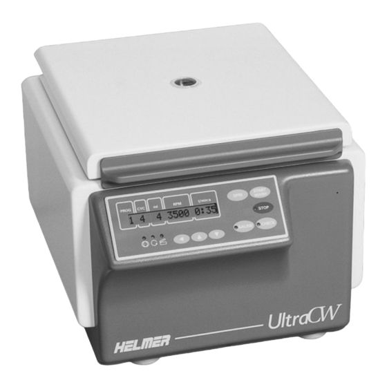
- Page 1 Automatic Cell Washing System Operation Manual UltraCW™ Version B Model UltraCW™ HELMER, INC. 14395 BERGEN BLVD., NOBLESVILLE, IN 46060 USA PHONE (317) 773-9073 FAX (317) 773-9082 USA and CANADA (800) 743-5637 www.helmerinc.com 360084-1/H...
-
Page 2: Table Of Contents
Contents Contents About this manual ............iv 1 Working safely . - Page 3 UltraCW™ Automatic Cell Washing System Operation Manual 5 Using the cell washer ........... .24 Preparing the rotor .
- Page 4 About this manual 8 Reference information ........... .47 8.1 Technical Specifications .
-
Page 5: About This Manual
Model references Generic references are used throughout this manual to group models that contain similar features. For example, “UltraCW” refers to both the 115 V and 230 V models. If a feature or procedure applies to a specific voltage, it is stated as such. -
Page 6: Working Safely
Working safely Working safely This section describes general safety information for installing, using, and maintaining the UltraCW Automatic Cell Washing System (“cell washer”). Your organization may provide additional safety information. General safety To avoid injury to yourself and the cell washer, follow these safety instructions: ► Use the cell washer for the purpose for which it was designed. -
Page 7: Chemical And Biological Safety
WARNING: Before sending parts to Helmer or your distributor for service or repair, decontaminate them as appropriate. Any items that have not been decontaminated appropriately will not be accepted. Documentation stating that the contents are not contaminated and are safe to handle must accompany all returns. -
Page 8: Touring The Cell Washer
Touring the cell washer Touring the cell washer Congratulations on your purchase of an UltraCW Automatic Cell Washing System. The cell washer provides advanced capabilities and outstanding benefits to complete your cell washing tasks quickly, easily, and dependably. This section gives a brief overview of the components of the cell washer, as well as how to find identifying information. -
Page 9: Touring The Side
UltraCW™ Automatic Cell Washing System Operation Manual Touring the side View of right side of cell washer Label Description Function Fuse Prevents current overload Power switch Turns the cell washer on and off Power connector Interface for the power cord... -
Page 10: Touring The Control Panel
Touring the cell washer Touring the control panel Control panel (shown with cell washer turned off) Label Description Function Message screen Displays process information, programming prompts, and error messages SPIN button In display mode: Starts the process that uses the spinning group of parameters of the selected program START WASH In display mode: Starts the process that uses the washing group of... -
Page 11: Touring The Rotor
UltraCW™ Automatic Cell Washing System Operation Manual Touring the rotor Left: Top view of 12-place rotor with inserts installed. Right: Bottom view of 12-place rotor Label Description Function Tube holder insert Holds 10 mm x 75 mm tubes in the tube holders. -
Page 12: Installing The Cell Washer
For easy reference, write the serial number on the front of this manual. The serial number is needed to provide efficient service. The Product Specification label is located on the right side of the cell washer next to the power connector. Type: UltraCW Serial Number 0000000 Noblesville, IN USA www.helmerinc.com... -
Page 13: Powering The Cell Washer
UltraCW™ Automatic Cell Washing System Operation Manual Powering the cell washer 3.3.1 Installing the power cord The power cord is included but packaged separately from the cell washer. To install the power cord ► On the right side of the cell washer, connect the power cord to the connector. -
Page 14: Opening And Closing The Lid
Installing the cell washer To turn the power off ► Press the switch to the Off ( ) position. Opening and closing the lid The cell washer is equipped with an electronically controlled lock that prevents the lid from being opened during operation. -
Page 15: Removing The Transport Bolts
UltraCW™ Automatic Cell Washing System Operation Manual Removing the transport bolts Keep the transport bolts and removal tool for future use. NOTE: The transport bolts are located on the bottom of the cell washer. They keep the motor from moving during transport, and must be removed prior to use. -
Page 16: Connecting To The Saline Supply And Drain
You will need the Drain/Fill Tubing Assembly to replace the tubing. This kit is available for purchase from Helmer. For the recommended replacement schedule, see Section 6.1, “Reviewing the preventive maintenance schedule.” For replacement part numbers, see Section 8.1.7 “Supplies.”... -
Page 17: Connecting To The Saline Supply
UltraCW™ Automatic Cell Washing System Operation Manual 3.7.2 Connecting to the saline supply If the connector or tubing on your saline supply is larger than that for the cell washer, you can use an adapter. The adapter is included but packaged separately from the cell washer. -
Page 18: Programming The Cell Washer
Programming the cell washer Programming the cell washer When you program the cell washer, you are defining a process which will later be automatically executed when you start the program. You control the steps of the process by setting parameters, which are viewed and changed from two menus: the Global menu and the Program menu. - Page 19 UltraCW™ Automatic Cell Washing System Operation Manual For the cleaning process, this step is always executed first. The amount is preset at 10 ml per place on the rotor. The fill volume exceeds the capacity of the tube to aid in flushing the drainage system.
- Page 20 Programming the cell washer 4.1.2.4 Understanding the Drop spin-down step During the Drop spin-down step, the rotor spins at 2000 r/min for the specified time. This action forces drops that are clinging to the sides of the tubes to the bottom of the tubes, thereby increasing the sample yield.
-
Page 21: Understanding Programs And Parameters
UltraCW™ Automatic Cell Washing System Operation Manual 4.1.2.6 Understanding the Suspension-agitation step The Suspension-agitation step works the same as the Agitation step, but is executed differently. For this step to be executed, the Suspension step must first be executed, and both the Susp.Agit. global parameter and the SalSusp/ml program parameter must be enabled. - Page 22 Programming the cell washer Parameter Meaning Available values Shakings NOTE: The design for these two IMPORTANT: By default, the parameters is different from that Shakings parameter is selected ShakeT(min) for other parameters. Both of these and set to 15. To switch to the parameters are stored in the same ShakeT(min) parameter, press the location, and only one or the other is...
-
Page 23: Understanding Programs And Program Parameters
UltraCW™ Automatic Cell Washing System Operation Manual 4.2.2 Understanding programs and program parameters The cell washer has three types of programs that are used to automatically perform processes. Numbered programs. There are five programs, numbered 1 to 5, that are used to carry out washing, suspension, spinning, and agitation processes. - Page 24 Programming the cell washer The following is a list of the program parameters in the order that they appear in the Program menu. Some parameters may not appear if they are disabled through a related global parameter. Parameter Meaning Available values #Cyc/wash The number of times to For processes with basic wash cycles:...
-
Page 25: Viewing And Changing Global Parameters
UltraCW™ Automatic Cell Washing System Operation Manual Viewing and changing global parameters You can view and change global parameters through the Global menu. For information about global parameters, see Section 4.2.1, “Understanding global parameters.” For illustrations of the default view for selected programs, see Section 4.4.1, “Selecting a program.”... -
Page 26: Changing Global Parameters
Programming the cell washer 4.3.3 Changing global parameters To change a global parameter value NOTE: If you are changing any values, and do not press any of the buttons for approximately 16 seconds prior to saving, the message screen returns to the display mode for the selected program. -
Page 27: Viewing Program Parameters
UltraCW™ Automatic Cell Washing System Operation Manual 4.4.2 Viewing program parameters You can view either a summary or all of the program parameters for any numbered program or the Spin program. For descriptions of the program parameters, see Section 4.2.2, “Understanding programs and program parameters.”... -
Page 28: Changing Program Parameters
Programming the cell washer 4.4.3 Changing program parameters You can change the program parameters for any numbered program or the Spin program. For descriptions of the program parameters, see Section 4.2.2, “Understanding programs and program parameters.” To change the Program menu parameter values in a program NOTE: If you are changing any values, and do not press any of the buttons for approximately 16 seconds prior to saving, the message screen returns to the... -
Page 29: Ultracw™ Automatic Cell Washing System Operation Manual
UltraCW™ Automatic Cell Washing System Operation Manual Using the cell washer Preparing the rotor The cell washer can use either a 12-place rotor or a 24-place rotor. The rotor can hold either 10 mm x 75 mm tubes or 12 mm x 75 mm tubes. -
Page 30: Installing And Removing The Tube Holder Inserts
When the cell washer is shipped from the factory, inserts are installed. To remove them, you will need a small flat-head screwdriver. Tube holder inserts are available for purchase from Helmer. For replacement part numbers, see Section 8.1.7 “Supplies.” Left: Slot in insert (circled). Right: 24-place rotor with tube inserts in various stages of installation (no insert, partially installed, fully installed). -
Page 31: Confirming That The Rotor Is Balanced
UltraCW™ Automatic Cell Washing System Operation Manual 5.1.4 Confirming that the rotor is balanced The rotor must be balanced for the cell washer to operate. If the rotor is not balanced, the process is stopped, IMBALANCE appears on the message screen, and the Imbalance lamp lights. -
Page 32: Calibrating The Saline Volume
Using the cell washer Calibrating the saline volume During the Fill and Suspension steps in processes, saline solution is dispensed into the tubes. Calibrate the saline volume before first use, and regularly thereafter, to ensure that the correct amount is being dispensed. For the recommended schedule, see Section 6.1, “Reviewing the preventive maintenance schedule.”... -
Page 33: Dispensing And Measuring The Total Saline Volume
UltraCW™ Automatic Cell Washing System Operation Manual 5.2.2 Dispensing and measuring the total saline volume As part of the calibration process, measure the amount of saline solution that is dispensed. Afterwards, compare the measured value to the value that is displayed on the message screen. The value is the saline volume setting per tube multiplied by the number of places in the rotor. -
Page 34: Determining How Much To Adjust The Volume
Using the cell washer 5.2.3 Determining how much to adjust the volume After measuring the total saline volume, compare the displayed value to the measured value. If the measured value is within the range (±5%) for the displayed value, no change is needed. However, if the measured value varies more than 5% from the displayed value, you must adjust the volume to calibrate the saline volume. -
Page 35: Starting And Stopping Processes
UltraCW™ Automatic Cell Washing System Operation Manual Starting and stopping processes Be sure to verify the settings and change them according to your process NOTE: needs before using the cell washer. For more information, see Section 4, “Programming the cell washer.”... -
Page 36: Pausing And Resuming A Wash Process
Using the cell washer 5.3.2 Pausing and resuming a wash process Pausing a process allows you to access the tubes during a process, then continue with the process. When you pause a process, the process stops after the current step is completed, at which time you can open the lid. -
Page 37: Maintaining The Cell Washer
UltraCW™ Automatic Cell Washing System Operation Manual Maintaining the cell washer Long-term exposure to certain preservatives found in azide-free saline solutions CAUTION: may adversely effect certain plastic components within the cell washer. Routine housekeeping and cleaning practices will help to remove salt deposits in, and prolong the life of, these components. -
Page 38: Cleaning The Cell Washer
Maintaining the cell washer Task Daily Weekly Monthly Annually Replace the pump tubing. ► For more information and instructions, see Section 6.3, “Replacing the pump tubing.” Replace the tube holder inserts for 10 mm x 75 mm tubes. ► For more information and instructions, see Section 5.1.2, “Installing and removing the tube holder inserts.”... - Page 39 UltraCW™ Automatic Cell Washing System Operation Manual To install the drainage rings Place the lower drainage ring in the bowl so that the drain hole in the ring is directly above the drain in the bowl. Left: Lower drainage ring placed in the bowl. Right: Drain holes aligned.
-
Page 40: Flushing The System
Maintaining the cell washer 6.2.3 Flushing the system To clean and disinfect the cell washer, as well as remove blockages due to salt crystallization, use the Clean Program to flush the system with bleach solution and again with distilled water. The Clean Program consists of two parts: the Clean sequence and the Refill sequence. - Page 41 UltraCW™ Automatic Cell Washing System Operation Manual Purge the bleach solution from the system. Hold the waste container in front of the nozzle. Holding the waste container in front of the nozzle On the control panel, press and hold the SALINE button for about three seconds until the Saline lamp lights and REFILL process appears on the message screen.
-
Page 42: Cleaning The Fill Ports
Maintaining the cell washer 6.2.4 Cleaning the fill ports Clean the fill ports on the rotor regularly to remove any debris that was not removed when the system was flushed. Debris can clog the fill ports, preventing saline solution from entering the tubes. If you allow the rotor to dry after washing or suspension processes, debris may accumulate in the fill ports more quickly. -
Page 43: Replacing The Pump Tubing
You will need the Pump Tubing Assembly to replace the pump tubing. This kit is available for purchase from Helmer. For replacement part numbers, see Section 8.1.7 “Supplies.” To replace the pump tubing Turn off the cell washer and disconnect it from power. - Page 44 Maintaining the cell washer Install the new tubing assembly. Orient the tubing assembly so that the middle section of tubing is aligned with the tubing holder, then press the tubing into the holder. Wrap the tubing holder around the pump so the middle section of tubing is against the pump. While squeezing the tubing holder around the pump, turn the locking lever counter-clockwise until it locks in position.
-
Page 45: Replacing Tube Holders
All available places on the rotor must have tube holders installed for the rotor to be balanced. Use the following procedure to replace damaged or worn tube holders. Tube holders are available for purchase from Helmer. For replacement part numbers, see Section 8.1.7 “Supplies.”... -
Page 46: Understanding And Addressing Operational Issues
Understanding and addressing operational issues Understanding and addressing operational issues This section describes issues that you may experience while using the cell washer, and provides actions that you can take to correct them. Understanding and addressing error messages When the cell washer is in error mode, the cell washer is not operational. The error must be addressed and cleared. - Page 47 UltraCW™ Automatic Cell Washing System Operation Manual Error message Possible cause Action Continued Inserts are not installed ► Check that the inserts are installed IMBALANCE correctly correctly in all the tube holders. For (applies to 10 mm x 75 mm more information, see Section 5.1.2,...
- Page 48 Understanding and addressing operational issues Error message Possible cause Action N > MAX XX A component is faulty or ► Contact a qualified service technician. internal connections are loose. POWER INTERRUPT There was a power outage. ► Open the lid and press the START WASH button to clear the error message.
-
Page 49: Addressing Performance Problems
UltraCW™ Automatic Cell Washing System Operation Manual Addressing performance problems This section explains performance-related problems that may occur with the cell washer. Be sure that you have followed the appropriate laboratory procedures and used NOTE: the appropriate materials for the task. -
Page 50: Addressing Equipment Problems
Understanding and addressing operational issues Problem Possible Cause Action A cell button has not formed A 12-place rotor is being ► Verify that the rotor type that is or is too small. used, but a 24-place rotor is programmed matches what is being programmed. -
Page 51: Releasing The Lid Lock
Releasing the lid lock The UltraCW is equipped with an electronically controlled lock that prevents the lid from being opened during operation. If the lock is not working properly, or if the lid is closed and there is no power to the cell washer, you can release the lock manually. -
Page 52: Reference Information
Reference information Reference information This section includes technical specifications and sample programs. 8.1 Technical Specifications 8.1.1 Power 8.1.1.1 Input power Input power varies depending on the destination of the cell washer. The input power required for a particular cell washer is specified on the Product Specification label. The following options are available: ► 110 V to 127 V, 60 Hz ► 207 V to 253 V, 50 Hz to 60 Hz 8.1.1.2... -
Page 53: Supplies
UltraCW™ Automatic Cell Washing System Operation Manual 8.1.7 Supplies Description Part number Tube holder insert E2551 Tube holder (12 mm x 75 mm) E2197 Also available in a Kit (12 pieces): 400596-1 Pump tubing assembly 450005-1 Also part of the Tubing kit (450003-1), which includes the... -
Page 54: Sample Programs
Reference information Sample programs This section provides sample programs to further illustrate the effect of different settings on processes. For more information and instructions about programming, see Section 4, “Programming the cell washer.” NOTE: These programs are samples only. The cell washer has not been pre-programmed with these settings. 8.2.1 Sample single-cycle washing process For this sample, the process would be started by pressing the START WASH button. -
Page 55: Sample Multiple-Cycle Washing Process
UltraCW™ Automatic Cell Washing System Operation Manual 8.2.2 Sample multiple-cycle washing process For this sample, the process would be started by pressing the START WASH button. 3500 Cycle #1 Cycle #2 3000 2500 Spin Spin 2000 (2500 rpm for (2500 rpm for... -
Page 56: Sample Suspension-Only Process
Reference information 8.2.3 Sample suspension-only process For this sample, the process would be started by pressing the START WASH button. 3500 3000 2500 2000 1500 1000 Suspension (1100 rpm) Time elapsed in seconds Sample suspension-only process Global parameter settings (suspension-only process example) Global parameter Value Explanation... -
Page 57: Sample Suspension With Agitation Process
UltraCW™ Automatic Cell Washing System Operation Manual 8.2.4 Sample suspension with agitation process For this sample, the process would be started by pressing the START WASH button. 3500 3000 2500 2000 1500 Suspension (1100 rpm) 1000 Suspension-agitation (200 rpm for 8 cycles) -
Page 58: Sample Spinning-Only Process
Reference information 8.2.5 Sample spinning-only process For this sample, the process would be started by pressing the SPIN button. 3500 3000 2500 2000 Spin (2200 rpm for 1 minute 10 seconds) 1500 1000 Time elapsed in seconds Sample spinning-only process Global parameter settings (spinning-only process example) Global parameter Value... -
Page 59: Sample Spinning With Decanting Process
UltraCW™ Automatic Cell Washing System Operation Manual 8.2.6 Sample spinning with decanting process For this sample, the process would be started by pressing the SPIN button. 3500 3000 Spin 2500 (3000 rpm for 25 seconds) 2000 1500 1000 Decant (440 rpm) -
Page 60: Sample Spinning After Agitation Process
Reference information 8.2.7 Sample spinning after agitation process For this sample, the process would be started by pressing the SPIN button. 3500 3000 2500 Spin (2700 rpm for 1 minute) 2000 1500 1000 Agitation (200 rpm for 15 cycles) Time elapsed in seconds Sample spinning after agitation process Global parameter settings (spinning after agitation process example) Global parameter... -
Page 61: Sample Agitation-Only Processes
UltraCW™ Automatic Cell Washing System Operation Manual 8.2.8 Sample agitation-only processes The programming for an agitation-only process differs depending on how the program will be started. 3500 3000 2500 2000 1500 1000 Agitation (200 rpm for 1 minute) Time elapsed in seconds Sample agitation-only process 8.2.8.1... - Page 62 Reference information 8.2.8.2 Sample agitation-only process started with the SPIN button For this sample, the process would be started by pressing the SPIN button. Global parameter settings (agitation-only process started with SPIN button example) Global parameter Value Explanation VOLUME ADJUST XX Value depends on the calibration ROTOR: XX PLACE Value depends on the rotor being used.
-
Page 63: Warranty
Parts For a period of two (2) years, Helmer will supply at no charge, including freight, any part that fails due to defects in material or workmanship under normal use, with the exception of expendable items. Expendable items include specimen tubes, saline supply tubing, drain tubing, internal saline supply tubing, pump tubing, and saline supply fittings. - Page 64 HELMER, INC. 14395 BERGEN BLVD., NOBLESVILLE, IN 46060 USA PHONE (317) 773-9073 FAX (317) 773-9082 USA and CANADA (800) 743-5637 www.helmerinc.com...
Need help?
Do you have a question about the UltraCW and is the answer not in the manual?
Questions and answers