Table of Contents
Advertisement
Advertisement
Table of Contents

Related Manuals for AUTOFLAME MM80006

Summary of Contents for AUTOFLAME MM80006
- Page 1 Combustion Management Systems AUTOFLAME SENSORS GUIDE 04.08.2020...
- Page 2 SENSORS GUIDE 04.08.2020 This manual and all the information contained herein is copyright of Autoflame Engineering Ltd. It may not be copied in the whole or part without the consent of the Managing Director. Autoflame Engineering Ltd’s policy is one of continuous improvement in both design and manufacture. We therefore reserve the right to amend specifications and/or data without prior notice.
- Page 3 Autoflame product range, i.e. combustion, electrical and control. The sale of Autoflame’s systems and equipment referred to in this Manual assume that the dealer, purchaser and installer have the necessary skills at their disposal. i.e. A high degree of combustion engineering experience, and a thorough understanding of the local electrical codes of practice concerning boilers, burners and their ancillary systems and equipment.
- Page 4 Autoflame trained and certified technician. Any person installing, wiring, commissioning or adjusting the sensors without undergoing proper Autoflame training and without full understanding of the Micro Modulation (MM) system may put themselves and others in a seriously dangerous situation that can result in serious injury or even death, and may cause permanent equipment failure and substantial property damage.
-
Page 5: Table Of Contents
Contents AUTOFLAME SENSORS ....................... 6 GAS & AIR PRESSURE SENSORS (MK8 SERIES) ..............7 2.1. Installation ............................10 2.2. Mk8 MM Gas Pressure Sensor Applications ................... 13 2.2.1. VPS / Pressure Limits with Vent Valve ................13 2.2.2. VPS / Pressure Limits, No Vent Valve ................14 2.2.3. -
Page 6: Autoflame Sensors
Autoflame Sensors AUTOFLAME SENSORS Autoflame offers the following range of sensors for use with the Mk8 and Mini Mk8 MM systems: Air pressure sensors. • Gas pressure sensors. • • Oil pressure sensors. Temperature sensors. • • Steam pressure (load) sensors. -
Page 7: Gas & Air Pressure Sensors (Mk8 Series)
1/8” parallel NPT / BSP female Supplied with ¼” tapered NPT / BSP male nipple Flying lead connector torque 1 to 3Nm max. tighten by hand only, do not over-tighten Warranty 2 years limited warranty Autoflame Sensors Guide Page | 7... - Page 8 ±100 ±137.88 ±55.4 ±2 ATEX Certified Air Pressure Sensors Range Pressure Range Zero Range Part # mbar “wg mbar “wg MM80005/EXP ±68 ±27 ±1 ±1.36 ±0.54 ±0.02 MM80013/EXP ±137 ±55 ±2 ±2.74 ±1.1 ±0.04 Autoflame Sensors Guide Page | 8...
- Page 9 For example; a gas pressure sensor is required for the purpose of valve proving and gas pressure limits for a boiler with maximum gas pressure supply of 170mbar, therefore MM80008 should be selected. MM80011, MM80012, MM80014 or MM80006 should not be used. Wiring Gas / Air Pressure Sensor to an MM...
-
Page 10: Installation
The gas pressure sensor is rated IP52 / NEMA 3 if the atmospheric pressure port is not piped, the supplied plastic plug must be secured in place. Please check the Annex at the end of this manual for the explanation of different IP ratings. Figure 1.1. Correct Installation of the Gas Sensor Autoflame Sensors Guide Page | 10... - Page 11 Figure 1.2. Correct Installation of the Gas Pressure Sensor for IP65 / NEMA4 rating IP52 installation – Differential Pressure port is not IP65 installation – Differential pressure port is piped piped (plastic cap must be placed) Autoflame Sensors Guide Page | 11...
- Page 12 Air Pressure Sensor Differential Pressure The Autoflame Air Pressure Sensor has a differential pressure port, this can be installed as shown below to measure a differential pressure. This is necessary where the air pressure at low fire is below 1 mbar (0.4 "wg) or when it is a local code requirement.
-
Page 13: Mk8 Mm Gas Pressure Sensor Applications
Gas & Air Pressure Sensors (Mk8 Series) 2.2. Mk8 MM Gas Pressure Sensor Applications Autoflame Gas Pressure Senor can be used with the Mk8 MM for the purpose of Valve Proving System (VPS) or Gas Pressure Limits or both at the same time. -
Page 14: Vps / Pressure Limits, No Vent Valve
1. pressure Limits, Valve Fuel Pressure Sensor Mode 2. Pressure Limits Proving 127 (Fuel 3) 128 (Fuel 4) 4. Vent Normally Closed, Single Valve Pilot. Gas Valve Configuration 5. Vent Normally Open, Single Valve Pilot . Autoflame Sensors Guide Page | 14... -
Page 15: Vps / Pressure Limits, No Vent Valve, Single Valve Pilot
127 (Fuel 3) Proving 128 (Fuel 4) Gas Valve Configuration 3. No Vent Valve, Single Valve Pilot. 2.2.5. External VPS Autoflame gas pressure sensor is not used. Option / Parameter Option # Setting for VPS 125 (Fuel 1) 126 (Fuel 2) Fuel Pressure Sensor Mode 3. -
Page 16: Mini Mk8 Mm Gas Pressure Sensor Applications
125 (Fuel 1) 1. pressure Limits, Valve Fuel Pressure Sensor Mode 2. Pressure Limits Proving 126 (Fuel 2) VPS Sensor Type 1. Pressure Sensor 1. Vent Normally Closed Gas Valve Configuration 2. Vent Normally Open Autoflame Sensors Guide Page | 16... -
Page 17: Vps/ Pressure Limits, No Vent Valve
Fuel Pressure Sensor Mode 2. Pressure Limits 126 (Fuel 2) Proving VPS Sensor Type 1. Pressure Sensor 4. Vent Normally Closed, Single Valve Pilot. Gas Valve Configuration 5. Vent Normally Open, Single Valve Pilot . Autoflame Sensors Guide Page | 17... -
Page 18: Vps / Pressure Limits, No Vent Valve, Single Valve Pilot
The pressure detected is the static line pressure, so the pressure switch should be set at a value just below this line pressure. When the burner is firing, terminal 82 is not checked. Autoflame Sensors Guide Page | 18... -
Page 19: External Vps
Gas & Air Pressure Sensors (Mk8 Series) 2.3.6. External VPS Option / Parameter Option # Setting for VPS 125 (Fuel 1) Fuel Pressure Sensor Mode 1. Valve Proving, Pressure Limits 126 (Fuel 2) VPS Sensor Type 0. Mains Input Autoflame Sensors Guide Page | 19... -
Page 20: Valve Proving Time And Pressure Change
Set option and parameter 133 = 12.5 mbar Note: This is a metric formula, therefore imperial units must be converted before applying this calculation. Conversion PSI to mbar to Litres /hr to Litres Multiplier 68.94. 28.31 28.31 Autoflame Sensors Guide Page | 20... - Page 21 Gas & Air Pressure Sensors (Mk8 Series) Mk8 MM Gas Valve Proving / Oil High-Low Pressure Limits Diagram The figure above shows the sequence for the Mk8 MM gas valve proving and high/low pressure limits using an Autoflame gas sensor. Autoflame Sensors Guide Page | 21...
-
Page 22: Combustion Air Pressure Proving
2. Minimum pressure in normal run mode must be higher than position 2. 3. Position 8 must be set equal to position 2 or higher. 4. Default settings for minimum and maximum is 15% above and below entered value. Autoflame Sensors Guide Page | 22... -
Page 23: Draft Pressure Control - Mk8 Mm
Wiring Wire Colour Mk8 MM Terminal Brown RS485 - Purple RS485 + Blue 0V DC 15V DC Screen Do not connect at MM side Autoflame Sensors Guide Page | 23... -
Page 24: Gas / Air Pressure Monitoring With Mk8 Dti
The Pressure Sensor screen on the DTI displays the status of all the sensors connected directly to the DTI. This screen also provides history graphs for the logged data. Pressure Sensor Screen on the DTI Autoflame Sensors Guide Page | 24... -
Page 25: Oil Pressure Sensor
Oil Pressure Sensor OIL PRESSURE SENSOR Autoflame oil pressure sensor can be used with the Mk8 MM for the purpose of checking the running oil pressure and setting up pressure limits when firing on liquid fuels. Specifications Part # MM60009... -
Page 26: Dimensions
Oil pressure switch – offset lower limit Oil pressure switch – offset upper limit Parameter 42 Oil pressure units Plug fits correctly in one position only, do not force. • • Do not use case to tighten pressure connection. Autoflame Sensors Guide Page | 26... -
Page 27: Steam Pressure Sensor
Steam Pressure Sensor STEAM PRESSURE SENSOR Autoflame Steam Pressure Sensor can be used with the MM system for the purpose of measuring the steam (load) pressure. Specifications Output Signal 1-6V IP rating NEMA rating Torque setting Max 25Nm Valve material... -
Page 28: Dimensions
80 bar (1160 PSI) 100 bar (1450 PSI) MM10009/U ¼” NPT tapered MM10017 ¼” BSP tapered 0 – 100 bar (0 – 1450 PSI) 200 bar (2900 PSI) 300 bar (4351 PSI) MM10017/U ¼” NPT tapered Autoflame Sensors Guide Page | 28... -
Page 29: Installation
The load sensor can be calibrated via Commissioning Mode or through Online Changes. The percentage change may not be linear to the current temperature, i.e. 80% of 10 bar may not translate to 8 bar. Autoflame Sensors Guide Page | 29... -
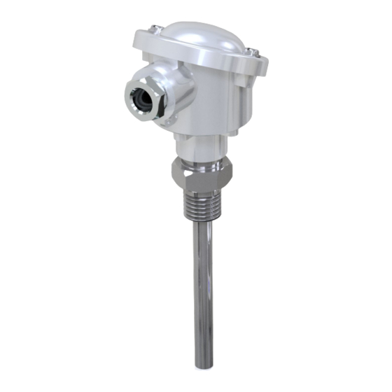
Page 30: Temperature Sensor
Temperature Sensor TEMPERATURE SENSOR Autoflame Temperature Sensor is a resistance type temperature detector for use with the MM system for the purpose of: Measuring load temperature. • • Monitoring the exhaust temperature or the coil/tube temperature of the boiler on the Mk8 Heat Flow metering applications on the Mk8 •... - Page 31 Temperature Sensor The table below provides the temperature vs. resistance data for the Autoflame temperature sensor: Temp. °C Temp. °F ꭥ ꭥ/°C ꭥ/°F 1000.0 3.90 2.17 1039.0 3.89 2.16 1077.9 3.88 2.16 1116.7 3.87 2.15 1155.4 3.86 2.14 1194.0 3.84 2.13...
-
Page 32: Dimensions
311.42 285.75 ½” BSP / NPT MM10006/200U ½” NPSM (12.26) (11.25) (8.86) MM10006/250 PG11 361.42 335.75 (14.23) (13.22) (10.63) (10) MM10006/250U ½” NPSM MM10006/400 PG11 511.42 485.75 MM10006/400U ½” NPSM (20.13) (19.12) (16.54) (12) Autoflame Sensors Guide Page | 32... -
Page 33: Temperature Sensor's Applications
Th temperature sensor can be used for several applications with the MM systems, please see the relevant MM manual for full details. Load Sensor Autoflame temperature sensor can be used as a load sensor with the Mk8 MM or Mini Mk8 MM, for this the following options must be set: Description... - Page 34 This alarm can only be reset when the spare temperature sensor reading drops below this threshold. The Exhaust Temperature Threshold is not an ultimate safety feature and it does not replace the need for high limit stat. Autoflame Sensors Guide Page | 34...
-
Page 35: Outside Temerate Compensation
If the actual outside temperature exceeds the boundaries set in options 82 and 84, the boiler setpoint will remain at the maximum or minimum setpoints specified by options 81 and 83. Please check the Mk8 MM and Mini Mk8 MM manuals for further details on Outside Temperature Compensation function. Autoflame Sensors Guide Page | 35... - Page 36 Outside Temperature Compensation Outside Temperature Compensation Screen – Mk8 MM Outside Temperature Compensation Screen – Mini Mk8 MM Autoflame Sensors Guide Page | 36...
-
Page 37: Outside Temperature Sensor
Outside Temperature Compensation 6.1. Outside Temperature Sensor Autoflame Outside Temperature Sensor can be wired directly to the Mk8 MM or connected to the Outside Temperature Compensation Module for use with the Mini Mk8 MM. The sensor’s body is made from aluminium and has 2 fixing holes to mount the sensor to a surface. -
Page 38: Outside Temperature Compensation Module
110V or 230V AC – switch must be set before use Communication RS485 IP Rating IP20 NEMA Rating Max. Operating Temperature 60°C (140°F) Min. Operating Temperature 0°C (23°F) Warranty 2 years limited warranty Drawing Autoflame Sensors Guide Page | 38... - Page 39 Outside Temperature Compensation Wiring Wire Colour Mini Mk8 MM Terminal Black RS485 - RS485 + Screen Autoflame Sensors Guide Page | 39...
-
Page 40: Annex: Ip Ratings
IP rating, (e.g. pushbuttons mounted in an enclosure). Different parts of enclosures can have different degrees of protection and still conform to the standard. Autoflame Sensors Guide Page | 40... - Page 41 AUTOFLAME SENSORS GUIDE 04.08.2020 Autoflame Engineering Ltd. Unit 1-2, Concorde Business Centre Airport Industrial Estate, Wireless Road Biggin Hill, Kent TN16 3YN United Kingdom Tel: +44 (0)1959 578 820 Email: technicalsupport@autoflame.com Website: www.autoflame.com Combustion Management Systems...
Need help?
Do you have a question about the MM80006 and is the answer not in the manual?
Questions and answers