Table of Contents
Advertisement
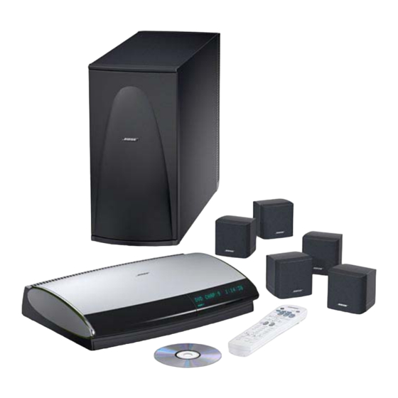
Digital Acoustimass
Lifestyle
®
28 Home Theater System
5 Double Cube Speakers
PS28 bass module
Power PCB, Assembly - 260327-001, Bare PCB - 266459-001
AMP PCB, Assembly - 266999-0, Bare PCB - 267083-001
DSP PCB, Assembly - 267391-0, Bare PCB - 267086-001
Service Manual
©
2005 Bose Corporation
®
Lifestyle
PS 18, 28 and 48
100V, 120V, 230V, Dual Voltage
®
Powered Speakers
®
Lifestyle
35 Home Theater System
5 Jewel Cube
PS48 bass module
Lifestyle
®
18 Home Theater System
5 Single Cube Speakers
PS18 bass module
Reference Number 268795-SM
®
Speakers
Rev 04
Electronic copy only
Advertisement
Table of Contents

Related Manuals for Bose Lifestyle PS 18


Summary of Contents for Bose Lifestyle PS 18
- Page 1 Power PCB, Assembly - 260327-001, Bare PCB - 266459-001 AMP PCB, Assembly - 266999-0, Bare PCB - 267083-001 DSP PCB, Assembly - 267391-0, Bare PCB - 267086-001 Reference Number 268795-SM Service Manual Rev 04 © 2005 Bose Corporation Electronic copy only...
-
Page 2: Table Of Contents
THIS DOCUMENT CONTAINS PROPRIETARY INFORMATION OF ® BOSE CORPORATION WHICH IS BEING FURNISHED ONLY FOR THE PURPOSE OF SERVICING THE IDENTIFIED BOSE PRODUCT BY AN AUTHORIZED SERVICE CENTER OR OWNER OF THE BOSE PRODUCT, AND SHALL NOT BE REPRODUCED OR USED FOR ANY OTHER PURPOSE. -
Page 3: Safety Information
• Transport or store ESDS devices in ESD protective bags, bins, or totes. Do not insert unpro- tected devices into materials such as plastic, polystyrene foam, clear plastic bags, bubble wrap or plastic trays. CAUTION: THE BOSE ® PS 28 AND PS 35 POWERED SPEAKER CONTAINS NO USER-SER- VICEABLE PARTS. -
Page 4: Specifications
PS18/28/48 Service Manual Specifications Mechanical Dimensions: Bass Module: 8.0" W x 23.0" D x 16.0" H (20.32 x 58.42 x 40.64 cm) Single Satellite: 3.1” W x 4.0” D x 3.1” H (7.0 x 10.2 x 7.9 cm) Double Satellite: 3.1"... -
Page 5: Part List Notes
48 system, refer to the instructions located on page 31 for setting the Equalizer using TAP ® commands. Except for the Lifestyle 18 system, in place of using TAP commands to set the EQ, ® the customer may use the Bose AdaptIQ audio calibration system to customize the EQ to their ® room. The Lifestyle 18 system bass module is set to provide a lower outut to match the single cubes, which can only be set using TAP commands. -
Page 6: Lifestyle ® 18 Home Theater System Packaging
PS18/28/48 Service Manual ® Lifestyle 18 Home Theater System Packaging Item Description Part Number Note Number CARTON 268787-001 PACKING, INSERT, GRILL 258465 PACKING, END CAP, EPS, FRONT 258466 PACKING, END CAP, EPS, REAR 258475 BAG, POLY 196638 PACKING PAD, 29.38X21.38 258469 AV28, US TUNER, RC1 266440-1019... -
Page 7: Lifestyle ® 28 Home Theater System Packaging
PS18/28/48 Service Manual ® Lifestyle 28 Home Theater System Packaging Item Description Part Number Note Number CARTON, RSC 258474-002 PACKING INSERT GRILLE 258465 PACKING END CAP EPS FRONT 258466 PACKING END CAP EPS REAR 258475 BAG POLY 196638 PACKING PAD 29.38X21.38 258469 AV28, US TUNER, RC1 266440-1019... -
Page 8: Home Theater System Packaging
PS18/28/48 Service Manual ® Lifestyle 35 Home Theater System Packaging Item Description Part Number Note Number CARTON, RSC 258474-002 PACKING INSERT GRILLE 258465 PACKING END CAP EPS FRONT 258466 PACKING END CAP EPS REAR 258475 BAG POLY 196638 PACKING PAD 29.38X21.38 258469 AV28, US TUNER, RC1 266440-1019... -
Page 9: Lifestyle 18/28/35 Essentials Kit Part List
PS18/28/48 Service Manual ® Lifestyle 18/28/35 Essentials Kit Part List Refer to figure 4 Item Description Part Number Variant Packaging Note Number US, CAN, AUS, EU, UK, SE ASIA/EAST ASIA, REMOTE CONTROL 256119-001 SING S. AF, MID E, DUAL-V REMOTE, CONTROL EU, 40MHZ 256119-002 BATTERY, AAA SIZE 179223-01... - Page 10 PS18/28/48 Service Manual Figure 4. LS18, 28, 35 Essentials Kit Exploded View...
-
Page 11: Lifestyle ® 18 Lit Kit Part List
AUS, EU, S. AF, MID E., UK, SING, SE CARD, INFO, WARRANTY, MULTI LANG 181460 ASIA/EAST ASIA SHEET SLIP COMPONENT AUDIO 255805 US, CAN, LATIN AMERICA ADDRESS PAGE, BOSE 259434 US, CAN, LATIN AMERICA CARD REGISTRATION AND WARRANTY 262933 CARD, LIFESTYLE UPDATE 268157 US, CAN, LATIN AMERICA AUS, EU, S. -
Page 12: 18 Single Cube Speaker, 5 Pack Packaging List
PS18/28/48 Service Manual ® Lifestyle 18 Single Cube Speaker, 5 Pack Packaging List Item Description Part Number Note Number SATELLITE ASSEMBLY, SINGLE, BLACK 250490-119 SATELLITE ASSEMBLY, SINGLE, WHITE 250490-129 CABLE, RJ-45/8 PIN DIN 260351-002 CABLE, AUDIO, DUAL RCA 185931-01 CABLE, VIDEO, 6', YL 183200 CABLE, S-VIDEO, 6’... - Page 13 PS18/28/48 Service Manual Figure 5. LS18, 28 Cube Pack Exploded View 9 13 Figure 6. LS35 Cube Pack Exploded View...
-
Page 14: Jewel Cube Part List
GRILLE, CUBE, WHITE, W/SLOT 192935-04 SNAP RING 178709 H-RING, SEAL, BLACK 178710-01 H-RING,SEAL NATURAL 178710-02 HARNESS ASSY, TWIDDLER 196136-01 SCREW, HILO, 4-16x.375, PAN, XREC 181621-06 DAMPER, ANTI-BUZZ 185951 NAMEPLATE, BOSE, BLACK/PEWTER 178725-01 NAMEPLATE, BOSE, WHITE/PEWTER 178725-02 Figure 7. Jewel Cube Exploded View... -
Page 15: Single And Dual Cube Speaker Part List
PS18/28/48 Service Manual Single and Dual Cube Speaker Part List Item Description Part Number Note Number GRILLE, BLACK 192410-019 GRILLE, WHITE 192410-029 LOGO, 1" DIAMOND CUT, BLACK 193250-11 LOGO, 1" DIAMOND CUT, WHITE 193250-12 Release the grille from these catches Figure 8. -
Page 16: Ps18/28/48 Bass Module Assembly Part List
® izer using TAP commands. Except for the Lifestyle 18 system, in place of using TAP commands to ® set the EQ, the customer may use the Bose AdaptIQ audio calibration system to customize the ® EQ to their room. The Lifestyle 18 system bass module is set to provide a lower outut to match the single cubes, which can only be set using TAP commands. -
Page 17: Ps18/28/48 Amplifier Module Assembly Part List
PS18/28/48 Service Manual PS18/28/48 Amplifier Module Assembly Part List Item Description Part Number Note Number POWER PCB ASSY, 120V 285837-001 1, 2, 3 POWER PCB ASSY, 230V 285837-002 POWER PCB ASSY, 120V/100V 285837-003 POWER PCB ASSY, DUAL-V 285837-006 AMP PCB ASSY 285826-001 1, 2 DSP PCB ASSY... -
Page 18: Ps18/28/48 Electrical Part List
PS18/28/48 Service Manual Power PCB Assembly 260327-XXXX, PCB 266459-001 PS18/28/48 Electrical Part List Resistors Reference Description Part Number Note Designator R101 10 OHM, 1206, 1/8W, 5% 124895-1005 R102 33 OHM, 1206, 1/8W, 5% 124895-3305 R103 10 OHM, 1206, 1/8W, 5% 124895-1005 R104 100 OHM, 1206, 1/8W, 5%... - Page 19 PS18/28/48 Service Manual Power PCB Assembly 260327-XXXX, PCB 266459-001 PS18/28/48 Electrical Part List Resistors (continued) Reference Description Part Number Note Designator R234 5.9K, 0603, .1W, 1% 191465-5901 R235 10K, 0603, .1W, 1% 191465-1002 R236 2.2 OHM, FUSING, 1/2W, 5% 188460-2R2 R237 2.2 OHM, FUSING, 1/2W, 5% 188460-2R2...
- Page 20 PS18/28/48 Service Manual Power PCB Assembly 260327-XXXX, PCB 266459-001 PS18/28/48 Electrical Part List Capacitors (continued) Reference Description Part Number Note Designator C122 220pF 0603, COG, 50V, 5% 188454-221 C126 .047uF, 0603, X7R, 5%, 25V 196999-473 C128 .047uF, 0603, X7R, 5%, 25V 196999-473 C129 .47uF, BOX, 85, 50V, 5%...
- Page 21 PS18/28/48 Service Manual Power PCB Assembly 260327-XXXX, PCB 266459-001 PS18/28/48 Electrical Part List Resistors (continued) Reference Description Part Number Note Designator D207 BAV70, SOT-23 147249 D208 SOT23, BAV99 147239 D209 1N4001, RECTIFIER, 400V, 1A 260340-1 D210 1N4001, RECTIFIER, 400V, 1A 260340-1 D211 BAV99, SOT23...
- Page 22 PS18/28/48 Service Manual Power PCB Assembly 260327-XXXX, PCB 266459-001 PS18/28/48 Electrical Part List Miscellaneous Reference Description Part Number Note Designator L101 2.2uH, COMMON MODE 187598-2R2 L102 2.2uH, COMMON MODE 187598-2R2 L103 1.5MH, 2.0A, TOROIDAL 269334-001 100V, 230V L201 12.5uH 176500 L202 12.5uH 176500...
- Page 23 PS18/28/48 Service Manual Amplifier PCB Assembly 266999-0, PCB 267083-001 PS18/28/48 Electrical Part List Resistors Reference Description Part Number Note Designator 5.1K, 0603, .1W, 5% 199403-512 100K, 0603, .1W, 5% 199403-104 2.0K, 0603, .1W, 1% 191465-2001 1.0K, 0603, .1W, 1% 191465-1001 10K, 0603, .1W, 5% 199403-103 10K, 0603, .1W, 5%...
- Page 24 PS18/28/48 Service Manual Amplifier PCB Assembly 266999-0, PCB 267083-001 PS18/28/48 Electrical Part List Capacitors Reference Description Part Number Note Designator 10uF, EL, 85, 25V, 20% 177902-100E 0.1uF, 0805, X7R, 50V, 10% 133624 0.1uF, 0805, X7R, 50V, 10% 133624 0.1uF, 0805, X7R, 50V, 10% 133624 0.1uF, 0805, X7R, 50V, 10% 133624...
- Page 25 PS18/28/48 Service Manual Amplifier PCB Assembly 266999-0, PCB 267083-001 PS18/28/48 Electrical Part List Diodes Reference Description Part Number Note Designator D101 BAV70, SOT-23 147249 D301 BAV70, SOT-23 147249 D401 BAV70, SOT-23 147249 D402 BAV70, SOT-23 147249 DIODE, ZENER, 3.3V 135247-5226 1N5236, DIODE, ZEN, 7.5V, 225 mW 135247-5236 Transistors...
- Page 26 PS18/28/48 Service Manual DSP PCB Assembly 267391-0, PCB 267086-001 PS18/28/48 Electrical Part List Resistors Reference Description Part Number Note Designator 2.2K, 0603, .1W, 5% 199403-222 47K, 0603, .1W, 5% 199403-473 47K, 0603, .1W, 5% 199403-473 22 OHMS, 0603, .1W, 5% 199403-220 47K, 0603, .1W, 5% 199403-473...
- Page 27 PS18/28/48 Service Manual DSP PCB Assembly 267391-0, PCB 267086-001 PS18/28/48 Electrical Part List Resistors (continued) Reference Description Part Number Note Designator R301 100K, 0603, .1W, 5% 199403-104 R302 10K, 0603, .1W, 5% 199403-103 R303 4.7K, 0603, .1W, 5% 199403-472 R416 100K, CHIP, 0805, 1% 133625-1003 R417...
- Page 28 PS18/28/48 Service Manual DSP PCB Assembly 267391-0, PCB 267086-001 PS18/28/48 Electrical Part List Resistors (continued) Reference Description Part Number Note Designator R616 100K, 0603, .1W, 5% 199403-104 R617 4.7K, 0603, .1W, 5% 199403-472 R619 3.32K, 0603, .1W, 1% 191465-3321 R620 36.5K, 0603, .1W, 1% 191465-3652 R621...
- Page 29 PS18/28/48 Service Manual DSP PCB Assembly 267391-0, PCB 267086-001 PS18/28/48 Electrical Part List Capacitors Reference Description Part Number Note Designator 47pF, 0603, COG, 50V, 5% 188454-470 .047uF, 0603, X7R, 25V, 5% 196999-473 2200pF, 0805, 50V, COG, 5% 133622-222 .047uF, 0603, X7R, 25V, 5% 196999-473 .047uF, 0603, X7R, 25V, 5% 196999-473...
- Page 30 PS18/28/48 Service Manual DSP PCB Assembly 267391-0, PCB 267086-001 PS18/28/48 Electrical Part List Capacitors (continued) Reference Description Part Number Note Designator C415 0603, X7R, 5%, 25V, .047uF 196999-473 C416 2.2uF, TANT, 10V, 20%, A SIZE 196981-A225A2 C418 220pF, 0603, COG, 50V, 5% 188454-221 C419 220pF, 0603, COG, 50V, 5%...
- Page 31 PS18/28/48 Service Manual DSP PCB Assembly 267391-0, PCB 267086-001 PS18/28/48 Electrical Part List Capacitors (continued) Reference Description Part Number Note Designator C601 100pF, 0603, COG, 50V, 5% 188454-101 C602 .047uF, 0603, X7R, 5%, 25V 196999-473 C603 .047uF, 0603, X7R, 5%, 25V 196999-473 C604 2.2uF, TANT, 10V, 20%, A SIZE...
- Page 32 PS18/28/48 Service Manual DSP PCB Assembly 267391-0, PCB 267086-001 PS18/28/48 Electrical Part List Integrated Circuits Reference Description Part Number Note Designator RECEIVER, SPDIF, CS8415A, SOIC 254193-001 VOLTAGE COMPARATOR, LM339 187618-001 DSP, QFP208, ADSP21065LKS 254191-001 U101 AND GATE, QUAD2-INPUT, CMOS 256124-001 U103 DSP, CS49329CL 254105-001...
-
Page 33: Setting Up A Computer To Issue Tap Commands
PS18/28/48 Service Manual Setting up a computer to issue TAP commands 1. Open a terminal window. Click: Start/Pro- 4. In the “COM1 Properties” window, make the gram/Accessories/Hyperterminal/Hyperterminal. selections in the various fields as shown. 2. In the “Connection Description” window, type the name “LS28, 35 bass module test”... - Page 34 PS18/28/48 Service Manual 9 PIN D-SUB FEMALE 8 PIN RJ45 RCA PLUG RJ45 8 PIN Figure 11. Test cable part number 264564...
-
Page 35: Placing The Bass Module Into Tap Mode
PS18/28/48 Service Manual Placing the Bass Module into TAP Mode Place all four DIP switches to the down position before returning the unit to the customer 1. Place the bass module into TAP mode 2. Verify the bass module communicates in TAP mode. -
Page 36: Test Procedures
PS18/28/48 Service Manual Test Procedures Test setup procedures 2 Bass Module Air Leak Test Place the bass module into TAP mode using the 2.1 Apply a 200 mVrms, 40 Hz signal to the procedures on page 26. input of the A-D converter. Note: Place all four DIP switches into the down position before returning the unit to the cus- 2.2 Check for air leaks from the cabinet. - Page 37 PS18/28/48 Service Manual Test Procedures 3.2 Measure the gain from the input to the A- 7. Bass Channel Large Signal Distortion D converter to the speaker output listed in the table below. 7.1 Apply a 100 Hz signal to the A-D converter input at a level to obtain 11 Vrms measured at Channel Gain...
-
Page 38: Bass Module Disassembly Procedures
PS18/28/48 Service Manual Bass Module Disassembly Procedures 1. Rear Cover Removal 2. Amp Module Removal Remove four screws - pull off cover Remove six screws - pull off amp module - unplug woofer harness 3. Amplifier Module Cover Removal 4. Power PCB Removal Remove 12 screws Disconnect J103, lift up PCB... - Page 39 PS18/28/48 Service Manual Bass Module Disassembly Procedures 5. DSP, AMP, AC Jack PCB Removal DSP PCB - Lift up DSP PCB. (ensure grounding clips remain in place) AMP PCB - Remove four screws, lift up AMP PCB. (ensure grounding clips and heat sink insulator remain in place, note spring bar location for reference when replacing) AC Jack PCB - Remove 2 screws, lift up AC Jack PCB.
-
Page 40: Cube Speaker Disassembly Procedures
PS18/28/48 Service Manual Cube Speaker Disassembly Procedures Double and Single Cube Disassembly 1. Double and Single Cube Grille Removal Remove grille with a flat plastic blade tool Note: The Twiddler speakers are not removable ® Jewel Cube Disassembly 1. Grille Removal 2. - Page 41 PS18/28/48 Service Manual Figure 13. PCB Part Number Identification Figure 14. Date Of Manufacture (DOM) Identification The DOM is the four underlined numbers in the serial number. Example: DOM 1303 -YDDD = 303rd day of 2001.
- Page 42 Revision Page Revison 00 - 01: Changed part number 260351-001 to 260351-002 per ECN32954 Revision 03-04 - Add new service bom part numbers for PCBs - new DSP PCB: ECN 36696...
- Page 43 Specifications and Features Subject to Change Without Notice Bose Corporation The Mountain Framingham Massachusetts USA 01701 R/N 268795-SM REV. 04 08/05 (H) http://serviceops.bose.com...
Need help?
Do you have a question about the Lifestyle PS 18 and is the answer not in the manual?
Questions and answers