
Related Manuals for Mo-vis Twister Pro


Summary of Contents for Mo-vis Twister Pro
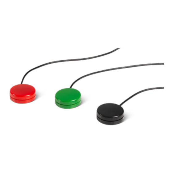
- Page 1 Installation manual Edition 1, August 2021 Twister Pro Twister Pro (D36) 1500 mm Black/Red/Green (P030-11/12/13) - Twister Pro (D36) 300 mm Black/Red/ Green (P030-21/22/23) moving forward together...
-
Page 2: Table Of Contents
Contents About this manual ................3 Installation manual ..............3 mo-vis bv ................... 3 Important information ................ 4 Warranty .................... 5 Repair and replacement ............5 Amendments ................5 Disclaimer and limitations of remedies ........6 Voiding of warranties ..............6 Technical support ................ - Page 3 Installation ..................12 Installation Plan ..............12 Installation ................13 Adjusting the dip switch ............14 External configuration ............... 16 Curtiss-Wright R-net parameters ..........16 Dynamic Controls parameters ..........17 Maintenance ..................19 Monthly inspection ..............19 Technical data ................... 20 Product description &...
-
Page 4: About This Manual
Please read it carefully before use and store safely for future reference. Our team will be happy to answer your questions. mo-vis bv Biebuyckstraat 15D . 9850 Deinze . Belgium http://www.mo-vis.com contact@mo-vis.com . +32 9 335 28 60 Twister Pro Installation manual... -
Page 5: Important Information
NOTICE: Only install this product on a wheelchair where the wheelchair manufacturer allows the installation of third party parts. Twister Pro Installation manual... -
Page 6: Warranty
2 years under proper use, care and service. The dealer should never keep mo-vis products in stock for a period more than 6 months prior to delivery to the end-user. mo-vis' warranty will never exceed a period of 2 years and 6 months after shipment. -
Page 7: Disclaimer And Limitations Of Remedies
The warranty will be void if the product has been installed or used improperly, or if it has been repaired or any part replaced by persons other than mo-vis or an authorized dealer. This product is considered as a non-serviceable part. -
Page 8: Technical Support
Technical support TROUBLE: In case of technical problems: Contact mo-vis at contact@mo-vis.com or +32 9 335 28 60. Always state the device serial number when contacting us. This ensures you are provided with the correct information. Twister Pro Installation manual... -
Page 9: Warning Labels
This symbol indicates caution for a hazardous situation that, if not avoided, could result in minor or moderate injury. WARNING: This symbol indicates a warning for a hazardous situation that, if not avoided, could result in death or serious injury. Twister Pro Installation manual... -
Page 10: Limited Liability
Limited liability mo-vis accepts no liability for personal injury or damage to property that may arise from the failure of the user or other persons to follow the recommendations, warnings and instructions in this manual. CAUTION: Carry out only the service and maintenance activities specified in this manual, as long as you comply with the demands stated in this manual for a specific action. -
Page 11: Operation
The Twister Pro is by default delivered and set as a normally open switch. Safety button The Twister Pro can also be configured using a dip switch on the bottom, so that it functions as a safety button. Twister Pro Installation manual... - Page 12 This provides additional safety to the device! NOTE: This feature allows to be compliant with the ISO 7176:14-2008 §7.2.3.4 Leakage Current Test. NOTE: This functionality is only possible when the host system supports this. Twister Pro Installation manual...
-
Page 13: Installation
A robust and reliable positioning. Hard or sudden movements of the wheelchair may not disorganize the installation. WARNING: Protect the device against bumps. Mind damaging the unit and wiring. Make sure that cabling is mounted in such a way that excessive wear and tear is avoided. Twister Pro Installation manual... -
Page 14: Installation
2 mm. If you use a thicker surface, be aware that the depth of the insert is 3 mm max. The connector jack should stay clean and needs to be inserted completely into the device. Twister Pro Installation manual... -
Page 15: Adjusting The Dip Switch
POSITION FUNCTIONALITY Default position: compatible with default systems which require a normally open connection. R-net resistor values: Compatible with Curtiss-Wright specifications for the CJSM II and Omni II. Twister Pro Installation manual... - Page 16 LiNX Band 10 resistor value LiNX Band 1 resistor value You can now reconnect and use the device. NOTE: Some R-net and LiNX parameters need to be set correctly before the safety switch functionality is operational. See Twister Pro Installation manual...
-
Page 17: External Configuration
Controls > Global > External Profile Jack Detect VALUE DESCRIPTION The Twister Pro will function as a normally open switch. The Twister Pro will be able to detect both open- and short-circuits in the wiring. If such conditions are detected, the function associated with the External Pro- file Switch Jack will be disabled and a warning will be displayed on the screen. -
Page 18: Dynamic Controls Parameters
VALUE DESCRIPTION The Twister Pro will function as a normally open switch. The Twister Pro will be able to detect both open- and short-circuits in the switch itself or its wiring. If such conditions are detected, a trip will occur. - Page 19 Control inputs can be configured to monitor for errors, such as short circuit, invalid open circuit, missing or unreliable states. mo-vis has chosen resistor bands 1 and 10: the Twister Pro can perform monitoring function in these bands, when the dip switch is set to the right...
-
Page 20: Maintenance
Monthly inspection Monthly, or whenever needed, check whether: • All bolts and screws are still firmly tightened. • There is no damage to any wiring. • There is no excessive wear to any of the parts. Twister Pro Installation manual... -
Page 21: Technical Data
Normally open. Optional safety feature based on resis- tor values: R-net: 490E and LiNX: 654E or 660E Activation Type The Twister Pro will be able to detect open- and short & Force circuits. The error is indicated to the user and logged in the system. - Page 22 75 gr/2.65 oz Maximum force 20 kg / 200N Connection 3.5 mm mono jack, cable length 300 or 1500 mm (11.8 or 59.06 in) Mounting 2 inserts M3 (3 mm/0.12 in depth, 23 mm/0.9 in cen- ter/center) Twister Pro Installation manual...
- Page 23 Twister Pro Installation manual...
- Page 24 Twister Pro Installation manual...
- Page 25 . Biebuyckstraat 15D . 9850 Deinze - Belgium www.mo-vis.com . contact@mo-vis.com . +32 9 335 28 60 Go to our website for more information on our products or share your experience with us via email.
Need help?
Do you have a question about the Twister Pro and is the answer not in the manual?
Questions and answers