Table of Contents
Advertisement
Quick Links
[ 1 ] GENERAL . . . . . . . . . . . . . . . . . . . . . . . . . . . . . . . . . . . . . . . . . . . 1-1
[ 2 ] SPECIFICATIONS . . . . . . . . . . . . . . . . . . . . . . . . . . . . . . . . . . . . 2-1
[ 3 ] OPTIONS SPECIFICATIONS . . . . . . . . . . . . . . . . . . . . . . . . . . . . 3-1
[ 4 ] PART NAMES AND FUNCTION . . . . . . . . . . . . . . . . . . . . . . . . . . 4-1
[ 5 ] UNPACKING AND INSTRATION . . . . . . . . . . . . . . . . . . . . . . . . . 5-1
[ 6 ] PICTURE QUALITY ADJUSTMENT . . . . . . . . . . . . . . . . . . . . . . . 6-1
[ 7 ] DISASSEMBLY AND REASSEMBLY . . . . . . . . . . . . . . . . . . . . . . 7-1
[ 8 ] ADJUSTMENT . . . . . . . . . . . . . . . . . . . . . . . . . . . . . . . . . . . . . . . 8-1
[ 9 ] SIMULATION AND DIAGNOSTICS . . . . . . . . . . . . . . . . . . . . . . . 9-1
[10] MAINTENANCE AND OTHERS . . . . . . . . . . . . . . . . . . . . . . . . . 10-1
Parts marked with "!" is important for maintaining the safety of the set. Be sure to replace these parts with specified
ones for maintaining the safety and performance of the set.
SERVICE MANUAL
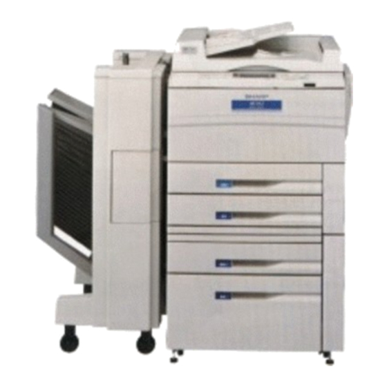
DIGITAL COPIER NO.1
MODEL
CONTENTS
SHARP CORPORATION
CODE: 00ZAR5132FM1E
AR-5132
This document has been published to be used for
after sales service only.
The contents are subject to change without notice.
Advertisement
Table of Contents

Subscribe to Our Youtube Channel
Related Manuals for Sharp AR-5132


Summary of Contents for Sharp AR-5132
- Page 1 SERVICE MANUAL CODE: 00ZAR5132FM1E DIGITAL COPIER NO.1 AR-5132 MODEL CONTENTS [ 1 ] GENERAL ......... . . 1-1 [ 2 ] SPECIFICATIONS .
- Page 2 CAUTION This copier machine is a class 1 laser product that complies with 21CFR 1040.10 and 1040.11 of the CDRH standard and IEC825. This means that this machine does not produce hazardous laser radiation. The use of controls, adjustments or performance of procedures other than those specified herein may result in hazardous radiation exposure.
- Page 3 CONTENTS 4. Transport base unit ....7-4 [ 1 ] GENERAL ......1-1 5.
- Page 4 (6) 1-set 2-copy [1] GENERAL The right and the left pages of a book, etc. can be copied into two sheets of paper continuously. 1. Features of copying functions (1) Various functions in the digital system Different from the conventional analog copiers, the original image data scanned by the CCD sensor (which converts optical signals into electrical signals) are converted into digital signals.
- Page 5 2. System outline (options) 20-bin sorter (SF-S15) Printer kit Connected to a computer Copied papers are sorted in the sequence to allow the machine to of pages or in each page automatically. be used as a printer. (Max. 20 sets of sorting is possible.) Staple sorter (SF-S53N) Copied papers are sorted in the sequence...
- Page 6 [2] SPECIFICATIONS Manual feed tray Tray type Folding type (2-stage telescopic) A3 ∼ A6R Copy paper size W letter size ∼ invoice form 1. Basic specifications Detectable paper size A3, B4, A4, A4R, A5 W-letter, Legal, Letter, Letter-R, Invoice (1) Type: Console Single feed: 56 ∼...
- Page 7 275 × 212 Letter-R (18) Machine configuration 136 × 212 Invoice Model Main body AR-5132 (14) Void area and image loss RADF Standard Void area Less than 3 mm at leading edge, less than 3 mm at Standard trailing edge, less than 5 mm in the sum of both.
- Page 8 2 – 3...
- Page 9 2 – 4...
- Page 10 2 – 5...
- Page 11 2 – 6...
- Page 12 [3] OPTIONS SPECIFICATIONS 1. SF-S15 Name 20-bin sorter No. of bins 20 bins Paper collection Copy face up Capacity per bin Max. 50 sheets (100 sheets: Top bin) Max. A3, Min.: B5 (Min. A6 for non-sort) Allowable paper size/weight Non-sort: 52 ∼ 128g/m for collating Sort/Grouping: 56 ∼...
- Page 13 [4] PART NAME AND FUNCTION 1. External view 1 2 3 7 8 9 11 12 13 16 17 18 19 20 21 22 23 24 Name Function Exit tray Finished copies are deposited in the exit tray. Paper clip tray Keep paper clip here.
- Page 14 2. Internal structure Name Function Fusing unit Fuses toner to paper. Transport level Turn to open the paper transport section. Corona unit The unit is used to charge the photoconductive drum. Photoconductive drum Copy images are formed on the photoconductive drum. Toner hopper Contains toner.
- Page 15 4 – 3...
- Page 16 4. Major parts 9.Cleaner unit 20.Main charger unit 10.Copy lamp 24.Mother PWB 12.Drum separation unit 8.CCD PWB 16.Lens unit 1.1st mirror 2.2nd mirror 3.3rd mirror 15.ICU PWB 25.OPC drum 19.LSU 40.Printer PWB (option) 11.Developer unit 13.Fuser thermistor 47.Transfer charger 50.Upper cleaning roller 44.Separation charger 51.Upper heat roller...
- Page 17 Part name Part name Part name 1st mirror Paper tray 3 pick-up roller 2 2nd mirror Main charger unit Paper tray 3 separation roller 3rd mirror Manual feed paper feed roller Paper tray 3 transport roller ADU paper feed roller Manual feed pick-up roller Printer PWB (Option) ADU pick-up roller...
- Page 18 5. Sensor 9.OCSW 7.MHPS 5.IR 1.BD 2.CSWF 17.PPD2 16.PPD1 10.P-SW 8.MPED 15.POD 14.PLS2 13.PLS1 3.CSWL 19.TFD 21.DPPD1 22.DPPD2 18.PSD 20.DPFD 25.DTWHPS 23.DTBHPS 24.DTPID 4.CSWR 12.PID 6.LUD2 11.PED3 33.DPOD1 42.LUD3 43.PED3 34.DPOD2 34.DPTD2 27.DLPD1 41.LMS2 26.DDOP 39.F/LSW 35.DPTD1 32.DPE2 29.DLPD3 30.DLUD1 31.DLUD2 28.DLPD2 38.E2CLK...
- Page 19 Section Name Function Contact / output 1 Main body BD Laser beam sensor Detection of laser beam start position CSWF Door switch Front Front door open / close detection ON when closed CSWL Door switch L Left door open / close detection ON when closed CSWR Door switch R...
- Page 20 6. Clutches and solenoid 9.DDC 6.RRC 5.PSPS 3.DGS 8.TRCL 7.TRCH 4.MPFS 10.DPFC 1.CRFC2 11.DRRC 2.CPFS2 18.RCL 13.DPFC1 12.BCL 14.DPFS1 16.P1CL 17.P2CL Section Name Function Type Main body CPFC2 Paper tray 1 pick-up clutch Paper tray 1 pickup roller rotation Electromagnetic clutch CPFS2 Paper tray 1 pick-up solenoid Paper tray 1 pickup roller pressing...
- Page 21 7. Motor 10.SM 12.VFM 1.CFM 4.LFM 3.DM 6.MM 8.PM 9.SFM 7.PCFM 2.DFM 14.PAM2 5.LUM1 13.PAM1 11.TM 18.LUM2 17.HMOT 15.E1MOT 16.E2MOT Section Name Function Type Main body Cooling fan motor Optical system cooling DC brushless motor Power supply motor Power supply cooling DC brushless motor Drum motor OPC drum, developing section drive...
- Page 22 8. PWB unit 23.Manual feed tray paper size sensor PWB 9.CCD drive PWB 25.Operation control PWB 24.Mother PWB 13.Discharge lamp PWB 15.Document size sensor PWB (Recieve side) 28.Process control volume PWB 21.LCD inverter PWB 18.ICU PWB 20.LCD control PWB 30.Printer PWB 22.LCD volume PWB 27.Polygon motor drive PWB 14.Document size sensor PWB (Emit side)
- Page 23 Name Function ICU PWB Image process control Laser drive PWB Laser beam drive LCD control PWB LCD display control LCD inverter PWB LCD backlight lighting LCD volume PWB LCD display density control Manual feed tray paper size sensor PWB Manual feed tray paper size detection Mother PWB ICU PWB, printer PWB interface Operation control PWB...
- Page 24 10. Desk unit (Major parts) 9.P1CL 2.E2MOT 12.Desk drive PWB 13.Desk main PWB 4.LUM2 10.P2CL 3.HMOT 11.RCL 6.DPFC1 5.BCL 1.E1MOT 7.DPFS1 Section Name Function Type Motor E1MOT Paper tray 3 lift-up motor 1 Paper tray 3 lift-up DC motor E2MOT Paper tray 3 lift-up motor 2 Paper tray 3 lift-up DC motor...
- Page 25 11. Desk unit (Sensor) 11.DPTD2 13.E2CLK 16.LMS2 15.LMS1 6.DLUD2 19.SIZESW 10.DPTD1 2.DLPD1 12.E1CLK 17.LUD3 18.PED3 7.DPE2 8.DPOD1 4.DLPD3 9.DPOD2 5.DLUD1 3.DLPD2 14.F/LSW 1.DDOP No. Section Name Function Type Contact/output 1 Desk DDOP Desk side open/close sensor Desk side door open/close Photo interrupter Low when desk side door is unit...
- Page 26 12. RADF (Sensor) 6.DLS1 12.TGOD 4.DED 7.DSS 3.RDD 10.AUOD 8.DFMRS 11.FGOD 9.DWS 5.DWVR 1.DFD 2.DTD Name Type Function, operation Contact point, output Document feed sensor Reflection sensor Becomes H level when the leading H level when document is detected. edge of document reaches the resist roller.
- Page 27 13. RADF (Motor) 3.DRM 2.DTM 1.DFM Name Function, operation Type Paper feed motor Driving of pick-up roller, separation roller, and resist roller DC motor Transport motor Driving of transport belt roller Stepping motor Reversion motor Driving of reversion roller and paper exit roller Stepping motor 14.
- Page 28 15. RADF (PWB) 1.Control PWB 5.Reversing sensor PWB 2.Document feed sensor PWB 4.LED PWB 3.Document timing sensor PWB Name Function Control PWB RADF control Document feed sensor PWB Detection of document feed Document timing sensor PWB Detection of document transport timing LED PWB LED lighting Reversing sensor PWB...
- Page 29 (4) Ensure that the area chosen for the machine location is level. [5] UNPACKING AND INSTALLATION 1. Use environment To ensure safety and proper machine performance, please note the following before initial installation and whenever the machine is to be relocated.
- Page 30 2. Unpacking (1) Package form drawing The PPC unit and the desk unit are separately packaged. Unpack the package in the following manner: A. PPC section Craft tape 50 mm wide a. Remove the PP band. Stitcher x 4 b. Remove the packing case. c.
- Page 31 B. Desk unit a. Cut the PP band. b. Open the exterior box. c. Remove the packaged items: 1) Remove the short spacer package assembly 2) Remove the screw package assembly A. 3) Remove the screw package assembly B. 4) Remove the instruction manual. d.
- Page 32 3. Setting-up procedure Included parts Parts for use with the Deck unit Installing desk unit Place the copier on the desk Secure the copier to the desk Mounting screws Connect the desk relay harness (4 pcs.) Secure the desk on the floor Parts for use with the SF-S53N Releasing optical system lock Setting fusing unit...
- Page 33 c. Remount the rear coverlet of the copier. C. Connect the desk relay harness. a. Remove the rear coverlet of the copier. Return the rear coverlet to its document position and use its mounting screw to mount it. Remove the mounting screw which holds the rear coverlet to the rear cabinet panel, then remove the rear coverlet.
- Page 34 (2) Releasing optical system lock B. Pressuring heat roller Move the pressuring levers at the front and rear sides of the fusing Remove the 2nd/3rd mirror unit locks. unit as shown in the figure below. This applies pressure on the upper Remove the screws securing the 2nd/3rd mirrors on the left side of and lower heat rollers.
- Page 35 d. Hook the CL spring on the front and rear frames of the fusing unit. (4) Cleaning the charger Make sure that the CL spring presses the bearing as shown in the A. Cleaning main charger unit electrode figure below. a.
- Page 36 d. Install the separation charger guide on the charger case. Insert B. Cleaning transfer/separation charger unit wire the transfer charger unit, along the groove in the guide, all the way a. Bring the transport opening/closing lever down to the left. Turn the to stop.
- Page 37 (6) Setting up developer unit B. Supplying developer a. Remove the connector which is connecting the toner hopper and A. Removing the developing unit. the developing unit. a. Open the front cabinet. Remove the five toner hopper fixing screws, the developing unit, b.
- Page 38 d. Install the toner cartridge to the toner box as shown in the figure C. Adjusting toner density sensor level below. Turn ON the power supply switch of the copier. Note: Make sure the main charger unit is securely inserted, before executing simulation 25-1 or 25-2.
- Page 39 h. Move the empty toner cartridge in the arrow direction to remove. b. Changing the side plates F and R sizes (factory set for A/3 or double letter size) Install the side plates F and R on the tray, along with the mark- ings, so that they form the paper size you want.
- Page 40 Size detection spacer setting Dummy slot W Letter Legal Letter R Letter Invoice e. Changing paper size indication plate Install the paper size indication plate so that the name of the paper size you preset can be seen through the paper size indica- tion window.
- Page 41 c. Adjust the side guides (9) Setting up paper tray 3 Remove the mounting screws (one per guide) holding the right and A. Paper size setting left paper side guides in place. a. Pull out the cassette. Use the mounting screws to secure the right and left paper size Grasp the cassette by the handle and pull it out gently as far as it will guides (one screw per guide) in the positions corresponding to the paper size which has been set.
- Page 42 d. Set the paper size switch f. Place the paper in the cassette. Set the paper size switch to match the paper size which has been Place paper in the right paper cassette.When doing this, do not stack set. the paper higher than the maximum height line indicated on the cas- sette.
- Page 43 B. Adjust any center misalignment. (10) Copy density check No adjustment should be needed for the unit as it is factory-set. After installing the copier, check the copy density. If the density is not However, if it is off-center, adjust it according to the following proce- in the specified range, adjust it.
- Page 44 Be sure that you have plenty of room around the copier for work space. Green label: 1 Support guide: 1 1.0m Sorter protection mat: 1 Remove the securing fixtures and attach the caster spacers. When performed on the skid. Remove the securing fixtures (2). Securing fixtures Stapling location label A: 1 Stapling location label D: 1...
- Page 45 When not performed on the skid Unplug the copier’s power cord before carrying out the following procedure. Open the sorter protection mat, as shown in the figure, and position it against the sorter’s casters. Lay the sorter down on the protection mat.
- Page 46 2 Confirm that the staple sorter locks into place beside the copier. 4. Attach the rail to the sorter. Insert the rail into the rail mounting anchor, on the bottom of the If not, adjust the height of the sorter mounting plate until the staple sorter, and attach them with the 2 rail screws A (M4 x 6) and 1 rail sorter locks securely into place.
- Page 47 10. Reattach the rear cabinet panel. 13. Set the mode. Reattach the rear cabinet panel in its document position with the • Perform the following key operations on the copier to set the mounting screws. mode. 11. Affix the stapling location labels. Affix the stapling location labels to the copier and RADF as shown in the figure.
- Page 48 2. Check the staple cartridge. 1. Remove the stapler unit. Confirm that the sheets of staples in the cartridge are properly stack- Open the stapler cover and remove the mounting screw securing the unit in place. If not, slide the staples back in the direction of the arrow while press- Next, remove the staple unit.
- Page 49 5. Reinstall the staple unit. (12) Install a sorter. (SF-S15) Reinstall the staple unit in its document location using the mounting <Option> screw to secure it in place. Then close the stapler cover. Staple unit SF-S15 Staple cover Mounting screw Parts list 6.
- Page 50 2. Mount the sorter seat to the desk. 4. Place the sorter on the sorter seat. Remove the two cut-outs in the cabinet panel on the left side of the While holding the handle, place the sorter on the sorter seat’s guide desk.
- Page 51 6. Connect the sorter connectors. 9. Adjust the clearance between the sorter and the copier. Use the two bracket mounting screws to secure the bracket attached to the sorter harness to the frame of the copier. Push the sorter gently against the copier’s left cabinet panel. The clearance spacers attached to the back of the sorter will determine Connect the 6-pin and 10-pin sorter connectors to the 6-pin and the standard clearance between the sorter and the copier.
- Page 52 (2) Adjusting process control sensor (picture [6] PICTURE QUALITY density sensor) output ADJUSTMENT Execute SIM 44-3. The OPC rotates and the drum marking sensor output adjustment value appears on the panel. 1. Initial setting of process control SIMULATION NO.44-3 Whenever the OPC drum or the process control PWB is replaced or ID SENSOR ADJUSTMENT the sensor is cleaned or replaced, or before the picture density is SENSOR RESPONSE:XXX...
- Page 53 • Lay A3 or W letter size paper, aligning their edges with the rear Lay 4 to 5 sheets of white paper (specified by Sharp), more than edge of the table glass and the OR guide L alignment position. 120 mm wide and about 420 mm long, one on top of another on (See the illustration.)
- Page 54 SIMULATION NO.26-27 30~170 IMAGE DENSITY MODE SETTING Make a copy. AUTO [X]:_1.(PEN) 2.(ORG) Make sure that the "4" of the Sharp test chart UKOG-0162FCZZ is MANUAL [X]:_1.(PEN) 2.(ORG) copied and the "3" is not copied. PHOTO [X]:_1.(PHOTO1) 2.(PHOTO2) (for the UKOG-0089CSZZ, the "0.3" should be copied and the SOFT_P [X]:_1.(SOFT_P1) 2.(SOFT_P2)
- Page 55 (2) Cleaning plate [7] DISASSEMBLY AND Remove the process unit from the machine. REASSEMBLY Remove the upper drum frame unit from the process unit. Remove the printer cable from the connector before trying to Screw Upper drum frame unit service or repair a digital copier with an optional printing function, with its rear cabinet removed.
- Page 56 (4) Separation pawl Remove the reverse roller unit. Remove the process unit from the machine. Plastic E ring Remove the separation pawl unit from the process unit. Separation roller unit Remove the separation pawl unit (R). Drum separation pawl unit (2) Pick-up roller Drum cleaner Remove the manual feed tray unit.
- Page 57 Remove the pick-up roller from the drive roller shaft assembly. Remove the E ring. Remove the pick-up roller lever. Pick-up roller E ring Pick-up roller lever Remove the paper feed roller from the drive roller shaft assembly. Remove both the paper feed roller and the pick-up roller. Pick-up roller Paper feed roller Paper feed roller...
- Page 58 (3) Solenoid Remove the paper feed-side roller toward the direction in which the paper is fed. Remove the spring. Remove the solenoid lever. Remove the suction holder. Remove the solenoid. Displace the suction transport belt toward the front frame and Spring remove.
- Page 59 Remove the spring and auxiliary roller. Displace the pressure spring lever and release the fusing pres- sure. Remove the PS roller. Loosen the set screw. Remove the screws securing the upper and lower units. Remove the front frame-side gear and remove the bearing. Remove the PS roller.
- Page 60 (Thermistor) Remove the upper cleaning roller. • Make sure the middle of the thermistor is in contact with the heat rollers. Front round hole • Remove any foreign matter from the thermistor surface with al- Fusing unit cohol. Rear round hole Upper heat roller Bearing Thermistor...
- Page 61 6. Auto duplex unit Push down the spring holder and remove the pick-up roller unit from the ADU. Remove the E ring from the side of the pick-up roller arm at the (1) Pick-up roller rear frame. Pull out the duplex copy tray. Remove the E ring from the side of the paper holding arm (at each Remove the ADU front cover and front cover a .
- Page 62 (3) Separation roller Remove the paper feed drive unit. Remove the upper and lower paper guides from the ADU. Remove the separation roller compression spring. Remove the separation roller. Remove feed shaft roller Paper feed drive unit Spring Spring (2) Paper feed speed-change unit Front F Rear F Spring color...
- Page 63 Remove the speed-change clutch connector and paper feed Remove the main drive unit. speed-change unit. Connecting plate Paper feed speed change unit Main drive unit (3) Main drive unit (4) DC power supply PWB Remove the rear cabinet from the machine. Remove the rear cabinet from the machine.
- Page 64 Remove the AC and DC power supply PWB. 8. Operation panel unit/Document size sensor PWB (light reception side) (1) Operation panel Open the front cabinet of the machine and remove the middle cabinet. DC power supply Middle cabinet AC power supply Remove the screws securing the glass holding plate at its front (5) Paper exit gate solenoid right and left.
- Page 65 (2) Document size sensor PWB (light reception 9. Optical unit side) (1) Copy lamp unit Remove the operation panel unit. Remove the right and left document guides and table glass. Remove the Document size sensor PWB. Table glass Document size sensor PWB Remove the dark box cover.
- Page 66 (2) Copy lamp How to stretch the mirror base wire (Check the following in advance.) Remove the right and left document guides and remove the table glass. Check the wire winding pulley stopping position. Displace the copy lamp unit to the notched part at the rear of the Check the wire winding pulleys (front/rear) have a wire groove in the upper cabinet.
- Page 67 (Rear frame side) View looking from rear frame (Front frame side) View looking from front frame 7 – 13...
- Page 68 Copy lamp unit installation position 2nd and 3rd mirror base unit installation position This is performed to adjust the parallelism of the mirror base B Pass the front and rear mirror base drive wires between the copy against the drum surface and document surface. lamp unit frame and the wire holder.
- Page 69 Open the front cabinet and remove the duct. Remove the right and left cabinets. Remove the process guide rail. Upper right cabinet Process guide rail Right-side cabinet Duct Note: Reinstall the table glass with the cut surface pointed up- ward. Remove the LSU lead wire connector.
- Page 70 12. RADF (1) Transport section opening Loosen screws which are fixing the hinge stopper to allow the hinge stopper to move. Slide the hinge stopper downward by using the step screw, fit the dove with the hole and tighten the fixing screws which were loosen before.
- Page 71 (5) Separation roller disassembly Remove the paper feed motor drive belt, and remove the four harness connectors. Then remove the paper feed unit. Open the paper feed cover. Remove fixing screws of the separation unit, and remove the separation unit. Screw Separation unit Harness...
- Page 72 (6) Semi-circular roller, paper feed roller (7) Open/close switch attachment disassembly When closing the transport section from the open state, adjust the DF open SW plate so that the clearance between the glass surface Open the paper feed cover. and the DF spacers L and R (front side) is 10 ∼ 40mm. Then tighten Loosen fixing screws of the tray guide top, and remove fixing the fixing screw.
- Page 73 [Note for assembly] (9) CONNECTOR LAYOUT When installing the document transport belt, put the right and left Control PWB peripheral in parallel, and allow the same clearance between the spacer and the belt in the front side and in the rear side. Spacer Spacer IF harness...
- Page 74 Paper feed motor peripheral Reverse unit section (Front side) Drive F harness Paper feed motor (DFM) Paper feed motor rotation sensor Paper feed RU harness guide switch (FGOD) Reverse solenoid (DRSOL) Document SENSOR 2 harness sensor (DSS) Reverse unit section (Rear side) SENSOR harness Reverse guide switch (TGD)
- Page 75 (2) Paper tray 3 section (LCC tray) 13. DESK UNIT A. Paper tray 3 (1) Paper tray 2 section a. Remove the desk cabinets R/L. A. Paper tray 2 b. As shown in the figure, press the lever upward or downward, to unlock the accuride and rail.
- Page 76 d. Remove the lifter guide rack. (3) Desk back cabinet section A. Paper tray 2 lift-up unit a. Remove the desk back cabinet. b. Pull out the connector and remove the paper tray 2 lift-up unit. (At this time, use caution not to break the lift-up unit latch. Connector(black) Type A Hook...
- Page 77 C. Drive unit (4) LCC paper transport section a. Remove the desk back cabinet. A. LCC paper transport unit b. Remove the drive unit. a. Remove the desk cabinets R/L. c. Remove the resist clutch harness. b. Remove the paper tray 2 and paper tray 3. d.
- Page 78 Note: D. Separation roller clutch • a. Remove the LCC paper transport unit. When removing, use caution not to break the latch. If the latch is accidentally broken, remove all fragments of the part to prevent b. Remove the E-ring and detach the bearing. any of them from getting caught in the gears and other parts.
- Page 79 E. Paper transport roller/Separation roller/Torque limiter B. Resist sensor a. Open the desk right door. a. Remove the resist roller unit. b. Remove the one-way clutch and paper transport roller. b. Remove the resist roller sensor unit. c. Remove the separation roller and torque limiter. Resist sensor 1 Screw Blue lead wire...
- Page 80 [8] ADJUSTMENT Item Contents Simulation Developing (1) Adjusting developing doctor clearance section (2) Adjusting developing magnet roller main pole position (3) Adjusting DV bias voltage 8-01 (4) Pay attention to the following points when installing developing unit rollers (5) Pay attention to the following points when attaching front and rear developing side seals.
- Page 81 (3) Adjusting DV bias voltage Set the digital multi meter range for DC 400V or more. Put the test rod between the DV bias output check pin (CP-B) and the chassis (GND). Keep needle away 2 or 3 mm (2) Adjusting developing magnet roller main pole position Execute SIM 8-1 to check the DV bias voltage.
- Page 82 2. Process section V ring φ6 V ring φ6 (1) Adjusting high voltage output and balance A. Using special measurement tools Electrode sheet (UKOG-0110FCZZ) V ring φ6 V ring φ6 Developing magnet roller 1) Pay attention to the direction of the V rings. 2) Make sure there is no clearance at the area where the V rings are in contact with each roller.
- Page 83 Green clip Orange Orange White Yellow clip Microswitch Black clip White Chassis (area not painted) Black Blue (DCmA) Blue clip Red clip Digital multimeter Clean the transfer charger wire and reinstall the transfer/separa- (UKOGE0043FC01) tion charger unit into the machine. (Do not install the main charger yet.) (Note) Connect the electrode sheet to the digital multimeter (or an am-...
- Page 84 (Measurement at high-voltage PWB check point) D. Adjusting separation charger output This adjustment should be performed with the electrode sheet not Remove the rear cabinet. used. Connect the digital multimeter to the grid voltage output check pin Install both the DV unit and drum holder unit on the copier. Power (CP-GB).
- Page 85 Make sure the saw blades are not deformed. Make sure the charger wire is not twisted or kinked. Make sure it is properly settled in the wire positioning groove in each holder. Make sure the charger case is clear of oil, contamination or foreign matter.
- Page 86 (Example) R s [ Put a scale on the document so that the 50-mm marking is positioned at the center of the document. A copy showing a checked pattern in self-printing mode is made. Copy magnification correction rate in main scanning direction 100 −...
- Page 87 (Example 1) Copy A Shorter than the actual size Screw (red) securing lens CCD unit * Under any circumstance, do not loosen this screw. Scale (Original) Adjustment may becom easier by inserting front cabinet hinge L angles (bars). * Two angles are needed. (Example 1) Copy B Longer thanthe actual...
- Page 88 (4) Adjusting distortion in lateral direction Set a sheet of white A3 or W letter size paper on the document table as shown below. If a copy image has a distortion in the lateral direction (or squareness Make a normal (100%) copy. against the scanning direction) without showing any distortion in the mirror base scanning direction, adjust the 2nd mirror base unit rail Measure the widths of the leading and trailing edges of the copy.
- Page 89 If Lc > Ld, move the paper feed-side mirror base B rail downward by half the difference between Lc and Ld. If Lc < Ld, move the paper feed-side mirror base B rail upward by half the difference between Ld and Lc. (When moving the mirror base rail, hold the mirror base rail handle.) Press keys in this order.
- Page 90 <In the case of setting by executing SIM 50-02.> Make copies in magnifications of 400%, 100% and 50% each, and check variations in the leading edge positions among these mag- In SIM 50-02, the leading edge can be easily adjusted by setting the nification settings.
- Page 91 Measure the distances L1 and L2 on the copied image and enter 5. Document detection section the measured values in steps of 0.1 mm on the operation panel display. (1) Adjusting document detection arm unit The screen can be switched over by using the message scroll key Adjusting OC switch On timing (→).
-
Page 92: Table Of Contents
(Entering document detection judgement level) (Sensor check mode) The reference value which determines whether an document is Execute SIM 41-01 to check photo sensor operation. (The system present or not is entered. In addition, the detection of the sensor is automatically enters the check mode after document detection judge- monitored based on this value. - Page 93 6. Others Execute SIM 50-12. (1) Printing off-center The printing off-center can be adjusted using manual paper feed as a reference, in the following manner: Check the setting of printing off-center in the manual paper feed mode, by executing SIM 50-10. Using manual paper feed setting as a reference, adjust the docu- ment (OC cover) off-center.
- Page 94 7. Paper tray 1/2 8. Paper tray 3 (LCC tray) (1) Adjust any center misalignment. (1) Adjust any center misalignment. Make a copy, and if there is any center misalignment such as that No adjustment should be needed for the unit as it is factory-set. shown in Fig.
- Page 95 (Example) To set a value (15) with two digit, perform the following When off center as shown in fig. 2 opeartion: Move the center adjuster in direction B and secure it with the two mounting screws. Make a copy to check whether it is centered proerly.
- Page 96 10. RADF (2) Document lead edge position adjustment. • The document lead edge position for RADF can be determined (1) Adjust any center misalignment. using the SIM 53. Set the original on the tray and make a copy. When the copy slips out •...
-
Page 97: Simulation No.41
[9] SIMULATION AND DIAGNOSTICS 3. Simulation sub code input screen SIMULATION NO.XX- _ 1. Start and end of simulations 1. X X X X X X X X X 2. X X X X X X X X X Note: The "PAUSE" key in the descriptions means the "INTER- n. - Page 98 • If there is the entry of data in the input field: 5. Setting input activation If the entered data is valid, the current setting in [ ] on the SIMULATION NO.XX-XX screen and in memory is updated by pressing the [PRINT] key. (The current setting in [ ] is rewritten.) After that, the screen returns to the preceding one.
- Page 99 Main Write in Adjustment Content Remarks code code memory range S-04 Checks the activation of the transport clutch. S-04 Checks desk load (upper tray paper feed solenoid). S-04 Checks desk load (upper tray paper feed clutch). S-04 Checks desk load (lower tray (LCC) paper feed solenoid). S-04 Checks desk load (lower tray (LCC) paper paper feed clutch).
- Page 100 Main Write in Adjustment Content Remarks code code memory range S-22 Displays counters. S-22 Displays maintenance counter. S-22 Displays maintenance counter preset. S-22 Displays JAM counter. S-22 Displays total counter. S-22 Displays developer counter. S-22 Displays developer preset counter. S-22 Displays RADF counter.
- Page 101 Main Write in Adjustment Content Remarks code code memory range S-42 Clears developer counter. S-43 Sets fusing temperature. S-43 Sets fusing temperature (normal mode). 160-205 S-43 Sets fusing temperature (economy mode). 0-45 S-44 Sets process control mode. S-44 Sets inhibit/enable of each mode of process control. S-44 Adjusts DM sensor.
- Page 102 Main Write in Adjustment Content Remarks code code memory range S-51 Timing adjustments. S-51 Sets separation nail activation timing. 20-90 S-51 Adjust resist amount, manual feed. Copy function available 0-50 Adjusts resist amount, cassette. Copy function available 0-50 Adjusts resist amount, ADU. Copy function available 0-50 S-52...
- Page 103 8. Detail of simulation Main Adjustment Item Content code code range SIMULATION NO. 1- _ Checks optical system. 1.OPTICAL SYSTEM CHECK 2.OPTICAL SENSOR CHECK INPUT SUB NO. AND PRESS PRINT SWITCH Checks mirror • Execution wait mode activation of SIMULATION NO. 1- 1 optical system.
- Page 104 Main Adjustment Item Content code code range SIMULATION NO. 1- 2 Displays operating status of optical OPTICAL SENSOR CHECK system sensor. MHPS , POWER [PAUSE]KEY: END DISPLAY [Content] Displays the operating status of the optical system and mirror motor. MHPS: Mirror home position sensor Mirror rotary encoder pulse POWER:...
- Page 105 Main Adjustment Item Content code code range SIMULATION NO. 2- 2 Displays the operating status of the RADF RADF SENSOR CHECK sensor. , DFD , DTD , RDD , AUOD FGOD , TGOD , DED1 , DWS1 , DWS2 DWS3 , DWS4 , DLS1 , DLS2 , DWS [PAUSE]KEY: END DISPLAY [Content] The operating status of the RADF sensor is displayed.
- Page 106 Main Adjustment Item Content code code range SIMULATION NO. 2- 4 Checks reverse rotation of paper feed MOTOR A REVERSE ROTATION motor. [PAUSE]KEY: END ACTIVATION [Content] The rotation of the RADF paper feed motor is reversed. (a) Operation/display [PAUSE]: The execution of the simulation is stopped and the screen returns to the sub code input screen.
- Page 107 Main Adjustment Item Content code code range SIMULATION NO. 2- 8 Checks paper feed solenoid activation. PAPER FEED SOLENOID ACTIVATION [PAUSE]KEY: END ACTIVATION [Content] The RADF paper feed solenoid is turned ON. (a) Operation/display [PAUSE]: The execution of the simulation is stopped and the screen returns to the sub code input screen.
- Page 108 Main Adjustment Item Content code code range Displays the • SF-S14 operating status SIMULATION NO. 3- 2 of sorter sensor. SORTER SENSOR CHECK , PWB-S , IULS , ILLS , IHS , SJS , UCSW , FCSW [PAUSE]KEY: END DISPLAY •...
- Page 109 Main Adjustment Item Content code code range SIMULATION NO. 3- 3 Checks the activation of the transport motor. TRANSPORT MOTOR ROTATION [PAUSE]KEY: END ACTIVATION [Content] The transport motor of the sorter is turned ON. (a) Operation/display [PAUSE]: The execution of the simulation is stopped and the screen returns to the sub code input screen.
- Page 110 Main Adjustment Item Content code code range SIMULATION NO. 3- 8 Checks the activation of the staple motor. STAPLER MOTOR ROTATION <SF-S53N only> [PAUSE]KEY: END ACTIVATION [Content] The activation of the sorter staple motor is checked. When there is a paper at the staple section, stapling action is performed once. (a) Operation/display [PAUSE]: The execution of the simulation is stopped and the screen returns to the...
- Page 111 Main Adjustment Item Content code code range SIMULATION NO. 4- _ Checks the activation of the desk. 2.DESK SENSOR CHECK 3, 4.TRAY SIZE SWITCH CHECK 6.TRANSPORT MOTOR ROTATION 7, 8.LIFT UP MOTOR ROTATION 10.TRANSPORT CLUTCH ACTIVATION 11,13.PAPER FEED SOLENOID ACTIVATION 12,14.PAPER FEED CLUTCH ACTIVATION INPUT SUB NO.
- Page 112 Main Adjustment Item Content code code range SIMULATION NO. 4- 3 Checks upper tray cassette size switch. TRAY SIZE SWITCH CHECK (UPPER TRAY) CSSW1 , CSSW2 , CSSW3 , CSSW4 [PAUSE]KEY: END DISPLAY [Content] Displays the operating status of the upper tray cassette size switch. Switches viewed from front frame side CSSW4 CSSW3 CSSW2 CSSW1 (a) Operation/display...
- Page 113 Main Adjustment Item Content code code range SIMULATION NO. 4- 7 Checks the activation of the upper tray lift-up LIFT UP MOTOR ROTATION (UPPER TRAY) motor. [PAUSE]KEY: END ACTIVATION [Content] The lift-up operation of the desk upper tray is checked. (The sensor is turned OFF when the upper limit is detected.) (a) Operation/display [PAUSE]:...
- Page 114 Main Adjustment Item Content code code range SIMULATION NO. 4-12 Checks the activation of the upper tray PAPER FEED CLUTCH ACTIVATION paper feed clutch. (UPPER TRAY) [PAUSE]KEY: END ACTIVATION [Content] The desk’s upper tray paper feed clutch is turned ON. (a) Operation/display [PAUSE]: The execution of the simulation is stopped and the screen returns to the...
- Page 115 Main Adjustment Item Content code code range SIMULATION NO. 5- 1 Checks the lighting of LED lamps on * SHOW THE DENSITY OF DISPLAY WITH TREE operation panel. STAGES. [PAUSE]KEY: END LAMP CHECK [Content] All the LED lamps on the operation panel are turned ON and held for 5 seconds. The RADF lamp (document (document feed/document remaining) comes on, too.
- Page 116 Main Adjustment Item Content code code range Checks lighting [Content] When the [PRINT] key is pressed after entering a sub code, the copier enters the 0-55 of copy lamp. execution wait mode, with the ready lamp coming on and the current copy lamp voltage setting displayed.
- Page 117 Main Adjustment Item Content code code range Sets copy lamp (a) Operation/display lighting voltage. [PRINT]: If the entered value is valid, the current setting is updated and the screen returns to the sub code input screen. If the entered value is invalid, the data in the input field is cleared and the error buzzer sounds.
- Page 118 Main Adjustment Item Content code code range SIMULATION NO. 7- _ Copy aging test. AGING TEST 1.WITH ALERT FOR MISFEED 2.WITHOUT ALERT FOR PAPER MISFEED 3.WITHOUT MISFEED AND FUSING 4.WARMUP DISABLED 6.INTERMITTENT AGING 7.INTERMITTENT AGING WITHOUT ALERT FOR PAPER MISFEED 8.WARMUP TIME DISPLAY INPUT SUB NO.
- Page 119 Main Adjustment Item Content code code range Warm-up [Content] 1. The warm-up is disabled. The optical system is initialized and shaded.The disabled. warm-up is disabled, but the fusing temperature control is performed. 2. The same applies to Door open clear/JAM clear/Economy mode return. If the [PRINT] key is pressed after entering a sub code, the copier exits the simulation mode and initializes and shades the optical system.
- Page 120 Main Adjustment Item Content code code range SIMULATION NO. 8- _ Checks developing bias voltage output. 1.DEVELOPING BIAS VOLTAGE SETTING AND OUTPUT 2.MAIN CORONA SETTING AND OUTPUT 6.TRANSFER CORONA OUTPUT 7.SEPARATION CORONA OUTPUT INPUT SUB NO. AND PRESS PRINT SWITCH Sets and •...
- Page 121 Main Adjustment Item Content code code range Sets and 0-700 SIMULATION NO. 8- 1 checks developing bias voltage. DEV. BIAS VOLTAGE OUTPUT SOFT PHOTOGRAPHIC MODE 0-700 SIMULATION NO. 8- 1 DEV. BIAS VOLTAGE OUTPUT TONER SAVE MODE 0-700 SIMULATION NO. 8- 1 DEV.
- Page 122 Main Adjustment Item Content code code range Sets and • Charging/grid bias outputting in progress checks SIMULATION NO. 8- 2 charging/grid 200-900 output. MAIN CORONA OUTPUT AUTO EXPOSURE MODE MAIN CORONA [XXX] [PAUSE]KEY: END OUTPUT CHECK SIMULATION NO. 8- 2 200-900 MAIN CORONA OUTPUT MANUAL EXPOSURE MODE...
- Page 123 Main Adjustment Item Content code code range Sets and (a) Operation/display checks [PRINT]: If the entered value is valid, the current setting is updated. charging/grid (The input field remains at the same place.) output. If the entered value is not valid, the entered value is cleared and the error buzzer sounds.
-
Page 124: Ab Series
Main Adjustment Item Content code code range SIMULATION NO. 9- 2 Displays the operating status of the ADU ADU SENSOR CHECK sensor. DPPD1 , DPPD2 , DTPID , DPFD DTWHPS , DTBHPS [PAUSE]KEY: END DISPLAY [Content] The operating status of the ADU sensor is displayed. DPPD1: ADU paper transport detector –... - Page 125 Main Adjustment Item Content code code range SIMULATION NO. 9- 5 Checks the activation of the gate solenoid. GATE SOLENOID ACTIVATION [PAUSE]KEY: END ACTIVATION [Content] The gate solenoid of the fusing paper exit section is turned ON/OFF. (a) Operation/display [PAUSE]: The execution of the simulation is stopped and the screen returns to the sub code input screen.
- Page 126 Main Adjustment Item Content code code range SIMULATION NO.17 Clears PF trouble. PF TROUBLE CANCELLATION PRINT SWITCH: EXECUTE SIMULATION [Content] The PF trouble is cleared. After the execution, the simulation is cleared. (a) Operation/display [PRINT]: The simulation is executed and the screen displays the main code input mode.
- Page 127 Main Adjustment Item Content code code range SIMULATION NO.21- _ Maintenance cycle setting. 1.MAINTENANCE CYCLE SETTING INPUT SUB NO. AND PRESS PRINT SWITCH Sets SIMULATION NO.21- 1 maintenance cycle. MAINTENANCE CYCLE SETTING [X] :_ 0. 80,000 SHEETS 1. 40,000 SHEETS 2.
- Page 128 Main Adjustment Item Content code code range SIMULATION NO.22- 1 Displays maintenance counter. MAINTENANCE COUNTER DISPLAY MAINTENANCE: XXX,XXX [PAUSE]KEY: END DISPLAY [Content] The current maintenance counter value is displayed. (a) Operation/display [PAUSE]: The execution of the simulation is stopped and the screen returns to the sub code input screen.
- Page 129 Main Adjustment Item Content code code range Displays total JAM counter. JAM map Cause display PFD paper misfeed (Paper stagnates at PDF or does not reach PPD1.) PPD1 PPD1 paper misfeed (Paper stagnates at PPD1 or does not reach PPD2.) PPD2 PPD2 paper misfeed (Paper stagnates at PPD2 or does not reach PSD.) PSD paper misfeed (Paper stagnates at PSD or does not reach...
- Page 130 Main Adjustment Item Content code code range Display total (a) Operation/display JAM counter. [?]: If the JAM counter is being displayed, the JAM map screen appears. If the JAM map counter is being displayed, the JAM counter screen appears. [→]: Displays the next JAM map screen.
- Page 131 Main Adjustment Item Content code code range SIMULATION NO.22- 8 Displays RADF counter. RADF COUNTER DISPLAY RADF: XXX,XXX [PAUSE]KEY: END DISPLAY [Content] The current RADF counter value is displayed. (a) Operation/display [PAUSE]: The execution of the simulation is stopped and the screen returns to the sub code input screen.
- Page 132 Main Adjustment Item Content code code range SIMULATION NO.22-12 Displays drum adjustment counter. DRUM ADJUSTMENT TIME DISPLAY DRUM ADJUSTMENT: XXX,XXX [S] [PAUSE]KEY: END DISPLAY [Content] The current value of the drum adjustment counter is displayed. (a) Operation/display [PAUSE]: The execution of the simulation is stopped and the screen returns to the sub code input screen.
- Page 133 Main Adjustment Item Content code code range SIMULATION NO.22-15 Displays trouble counter. TROUBLE COUNTER DISPLAY TROUBLE COUNTER: XXX,XXX TROUBLE MEMORY DISPLAY XX-XX, XX-XX, XX-XX, XX-XX, XX-XX XX-XX, XX-XX, XX-XX, XX-XX, XX-XX XX-XX, XX-XX, XX-XX, XX-XX, XX-XX XX-XX, XX-XX, XX-XX, XX-XX, XX-XX [PAUSE]KEY: END DISPLAY [Content] The current value of the total trouble counter and 20 trouble codes which have...
- Page 134 Main Adjustment Item Content code code range SIMULATION NO.22-20 Displays printer counter. PRINTER COUNTER DISPLAY PRINTER COUNTER: XXX,XXX [PAUSE]KEY: END DISPLAY [Content] The current value of the printer counter is displayed. (a) Operation/display [PAUSE]: The execution of the simulation is stopped and the screen returns to the sub code input screen.
- Page 135 Main Adjustment Item Content code code range SIMULATION NO.24- 1 Clears JAM counter/JAM map. TOTAL JAM / JAM MEMORY WOULD YOU MIND IF CLEARING EXECUTE? 1. EXECUTE 2. CANCEL SELECT WITH TEN KEY • [1] key SIMULATION NO.24- 1 TOTAL JAM / JAM MEMORY COMPLETED CLEARING TOTAL MISFEED COUNTER DISPLAY TOTAL JAM: 000,000...
- Page 136 Main Adjustment Item Content code code range Clears trouble [Content] The trouble counter is cleared. After that, the trouble counter is displayed. counter. (a) Operation/display [1]: The simulation is executed and the screen changes to the trouble counter screen. [2]: The simulation is stopped and the screen returns to the sub code input screen.
- Page 137 Main Adjustment Item Content code code range SIMULATION NO.24- 4 Clears RADF counter. RADF COUNTER WOULD YOU MIND IF CLEARING EXECUTE? 1. EXECUTE 2. CANCEL SELECT WITH TEN KEY • [1] key SIMULATION NO.24- 4 RADF COUNTER COMPLETED CLEARING RADF COUNTER DISPLAY RADF: 000,000 [PAUSE]KEY: END DISPLAY [Content] The RADF counter is cleared and then the RADF counter screen is displayed.
- Page 138 Main Adjustment Item Content code code range Clears staple [Content] The staple counter is cleared and then staple counter is displayed. counter. (a) Operation/display [1]: The simulation is executed and the screen changes to the RADF counter screen. [2]: The simulation is stopped and the screen returns to the sub code input screen.
- Page 139 Main Adjustment Item Content code code range SIMULATION NO.24- 8 Clears copy counter. COPY COUNTER WOULD YOU MIND IF CLEARING EXECUTE? 1. EXECUTE 2. CANCEL SELECT WITH TEN KEY • [1] key SIMULATION NO.24- 8 COPY COUNTER COMPLETED CLEARING COPY COUNTER DISPLAY COPY COUNTER: 000,000 [PAUSE]KEY: END DISPLAY [Content] The copy counter is cleared and then copy counter is displayed.
- Page 140 Main Adjustment Item Content code code range Clears PDA/ZR [Content] The PDA/ZR print counter is cleared and then PDA/ZR print counter is displayed. print counter. (a) Operation/display [1]: The simulation is executed and the screen changes to the PDA/ZR print counter screen.
- Page 141 Main Adjustment Item Content code code range SIMULATION NO.25- 1 Checks the activation of the main motor. MAIN MOTOR ACTIVATION DEVELOPER REFERENCE: XX [PAUSE]KEY: END DISPLAY [Content] The main motor/drive motor are rotated for 3 minutes to check the activation of the driving unit.
- Page 142 Main Adjustment Item Content code code range SIMULATION NO.25- 3 Sets toner 0-99 control ignorance time. TONER CONTROL MODE SETUP [XX]:_ [S] (0~99) INPUT SETUP VALUE AND PRESS PRINT SW [Content] The toner control ignorance time at the rotation of the main motor can be set in the range of 0 to 99 seconds.
- Page 143 Main Adjustment Item Content code code range SIMULATION NO.26- 1 Optional setting. 0-15 OPTION UNIT SETUP [XX] :_ 5.RADF + DESK 15.RADF + DESK + SORTER INPUT SETUP VALUE AND PRESS PRINT SW [Content] Optional setting can be made. The current setting is displayed and a new setting can be entered.
- Page 144 Main Adjustment Item Content code code range SIMULATION NO.26- 3 Sets counter mode. COUNTER MODE SETUP [X] :_ CODE TOTAL COUNT , MAINTE COUNT DOUBLE COUNT , DOUBLE COUNT SINGLE COUNT , DOUBLE COUNT DOUBLE COUNT , SINGLE COUNT SINGLE COUNT , SINGLE COUNT INPUT SETUP VALUE AND PRESS PRINT SW [Content] The counter’s count-up mode can be set.
- Page 145 Main Adjustment Item Content code code range SIMULATION NO.26-15 Sets fusing curl correction mode. FUSING CURL MODE SETTING [X] :_ 0. NORMAL MODE 1. FUSING CURL MODE INPUT SETUP VALUE AND PRESS PRINT SW [Content] The fusing curl correction mode can be set. If this mode is set, the driving unit rotates at all times during warming-up.
- Page 146 Main Adjustment Item Content code code range Sets power • Power save destination setting screen save destination. SIMULATION NO.26-26 POWER SAVE DESTINATION SETTING [X]:_ 0.OFF INPUT SETUP VALUE AND PRESS PRINT SW [Content] Used to set the power save destination. The power save time set by key operation P21 differs depending on the set destination.
- Page 147 Main Adjustment Item Content code code range SIMULATION NO.27- Sets PPC communication parameters. 1.PPC COMMUNICATION TROUBLE SETTING 2.PC/MODEM TELEPHONE NUMBER SETTING 3.PC/MODEM ID NUMBER SETTING 4.PPC SERVICE START/END SETTING 5.PPC TAG NUMBER SETTING INPUT SUB NO. AND PRESS PRINT SWITCH Sets PPC SIMULATION NO.27- 1 communication...
- Page 148 Main Adjustment Item Content code code range SIMULATION NO.27- 2 Sets PC/Modem telephone PC/MODEM TELEPHONE NUMBER SETTING number. SELECT HOST NUMBER (1-4):_ SELECT TELEPHONE NUMBER (1-4):_ INPUT SETUP VALUE AND PRESS PRINT SW SIMULATION NO.27- 2 PC/MODEM TELEPHONE NUMBER SETTING CURRENT TELEPHONE NUMBER HOST 1/TEL#1 XXXXXXXXXXXXXXXXXXXXXXXX...
- Page 149 Main Adjustment Item Content code code range SIMULATION NO.27- 3 Sets PC/Modem ID PC/MODEM ID NUMBER SETTING number. WHICH DO YOU CHANGE ID NUMBER (1 or 2) 1. PPC 2. PC/MODEM SELECT WITH TEN_KEY • When “1” is selected: SIMULATION NO.27- 3 PPC ID NUMBER SETTING PPC CURRENT ID NUMBER XXXXXXXXXX...
- Page 150 Main Adjustment Item Content code code range SIMULATION NO.27- 3 Sets PC/Modem ID number. PC/MODEM ID NUMBER SETTING PC/MODEM CURRENT ID NUMBER XXXXXXXXXX [PAUSE]KEY:END DISPLAY [Content] The ID numbers of the PPC and PC/Modem in the PPC communication system can be set. Select which ID number you want to set, one for the PPC or one for the PC/Modem.The screen displays the current ID number setting.
- Page 151 Main Adjustment Item Content code code range Sets start/end [Content] The start/end of service in the PPC communication system can be set. Select of service. either the start service or the end of service and the PPC will send the correspond- ing command to the PC/Modem.
- Page 152 Main Adjustment Item Content code code range SIMULATION NO.30- _ Displays the operating status of the 1.MONITORING MAIN UNIT PAPER SENSOR paper/cassette sensors. 2.MONITORING PAPER CASSETTE SIZE INPUT SUB NO. AND PRESS PRINT SWITCH SIMULATION NO.30- 1 Displays the operating status of the copier sensors.
-
Page 153: Simulation No.41
Main Adjustment Item Content code code range Displays the • Cassette size switch operating status Switches looking from the front frame side of paper size CSS4 CSS3 CSS2 CSS1 detection switch. Operation/display [PAUSE]: The execution of the simulation is stopped and the sub code input screen is displayed. -
Page 154: Simulation No.41
Main Adjustment Item Content code code range SIMULATION NO.41- 2 Adjusts the 0-255 document size detection ORIGINAL SIZE PHOTOSENSOR SETUP sensor. WITH THE ORIGINAL COVER OPENED, TURN ON THE PRINT SWITCH WITH NO ORIGINAL ON THE ORIGINAL TABLE. [PAUSE]KEY:END DISPLAY SIMULATION NO.41- 2 ORIGINAL SIZE PHOTOSENSOR SETUP SET AN A3-SIZE COPY PAPER ON THE... -
Page 155: Rcv Lv Setup Xxx
Main Adjustment Item Content code code range Adjusts the [Content] The detection level of the document size detection sensor is adjusted.If the document size [PRINT] key is pressed with the document cover open and without placing any detection document, the output level of the sensor that has detected no document is read. sensor. - Page 156 Main Adjustment Item Content code code range SIMULATION NO.42 Clears developer counter. DEVELOPER COUNTER CLEAR WOULD YOU MIND IF CLEARING EXECUTE? 1. EXECUTE 2. CANCEL SELECT WITH TEN KEY • [1] key SIMULATION NO.42 DEVELOPER COUNTER CLEAR COMPLETED CLEARING DEVELOPER COUNTER DISPLAY DEVELOPER:000,000 [PAUSE]KEY:END DISPLAY [Content] The developer counter is cleared and then the developer counter is displayed.
- Page 157 Main Adjustment Item Content code code range Sets fusing [Content] The current setting of fusing temperature in the normal mode is displayed and a temperature new setting can be entered. (normal mode). Operation/display [PRINT]: If the entered value is valid, the current setting is updated and the screen changes to the sub code input screen.
- Page 158 Main Adjustment Item Content code code range SIMULATION NO.44- 1 Sets each mode of process control. PROCESS CONTROL MODE SETUP[X]:_ PROCESS DRUM CONTROL ADJUSTMENT INPUT SETUP VALUE AND PRESS PRINT SW [Content] The current setting of process control is displayed and a new setting can be set. After the execution of the simulation, the screen returns to the sub code input screen.
- Page 159 Main Adjustment Item Content code code range SIMULATION NO.44- 4 Sets standard 0-255 patch density. PROCESS CONTROL INITIAL DENSITY SETUP INITIAL DENSITY[XXX]: XXX (0~255) INPUT SETUP VALUE AND PRESS PRINT SW [Content] The current setting of the standard patch density during process controlling is displayed and a new setting can be set.
- Page 160 Main Adjustment Item Content code code range Displays [Content] Process control data are displayed. process control data. STD_PAT The standard patch density (Setting of SIM44-04) DRUM_CNT Drum adjustment counter P_CNT Patch read count in the previous process control GRID_BIAS (ORG) Grid bias setting GRID_BIAS (ADJ) Grid bias adjustment value...
- Page 161 Main Adjustment Item Content code code range SIMULATION NO.46- _ Adjusts exposure level. 1.EXPOSURE LEVEL ADJUSTMENT (COPY) 2.EXPOSURE LEVEL SETTING (EACH MODE) 3.EXPOSURE LEVEL SETTING (COPY) 7.TONE ADJUSTMENT SETTING (COPY) INPUT SUB NO. AND PRESS PRINT SWITCH Adjusts [Content] The exposure level in the copy mode can be adjusted. AE: 30-170 ME: 30-170 exposure level...
- Page 162 Main Adjustment Item Content code code range Adjusts To clear the exposure adjustment mode: exposure level 1. Turn ON the [CA] key, or (copy). 2. Turn ON/OFF the main switch (on the left-side of the copier), or 3. Enter the simulation mode and press the [CA] key to exit the simulation mode. SIMULATION NO.46- 2 Inputs exposure AE: 0-200...
- Page 163 Main Adjustment Item Content code code range SIMULATION NO.46- 3 Inputs exposure AE: 30-170 ME: 30-170 level adjustment PH: 30-170 value (copy). SPH: 30-170 EXPOSURE LEVEL SETTING (COPY) AUTO AE_3.0 (30~170) [XXX]:XXX MANUAL N_3.0 (30~170) [XXX]:XXX PHOTO P1_3.0 (30~170) [XXX]:XXX SOFT_P SFT_3.0 (30~170) [XXX]:XXX [|]KEY:MOVE...
- Page 164 Main Adjustment Item Content code code range SIMULATION NO.48- _ Zoom adjustment. 2.ZOOM ADJUSTMENT (PAPER MOVING DIRECTION) INPUT SUB NO. AND PRESS PRINT SWITCH Zoom [Content] The copy ratio in the scanning direction can be adjusted. The current copy ratio SKN: 0-20 adjustment setting in the scanning direction can be separately changed.
- Page 165 Main Adjustment Item Content code code range SIMULATION NO.50- _ Adjusts the leading edge 1, 2, 5.ADJUST THE COPY LEAD EDGE position of the IMAGE LOSS AND VOID AREAS copy. 3.SET THE COPY LEAD EDGE IMAGE LOSS AND VOID AREAS 10.PRINT OFCENTER ADJUSTMENT 12.ORIGINAL OFCENTER ADJUSTMENT 14.PRINT OFCENTER SETTING...
- Page 166 Main Adjustment Item Content code code range Adjusts the Operation/display leading edge [PRINT]: If the entered value is valid, the current setting is updated. (The input field position of the remains at the same position.) image. If the entered value is not valid, the input field is cleared and the error buzzer sounds.
- Page 167 Main Adjustment Item Content code code range Adjusts the WARMING UP. leading edge PLEASE WAIT. position of the image READY TO COPY (calculation IMAGE POSITION formula). ADJUSTMENT (TRAY) L1[0.1mm] COPY RATIO 400% • [→] key READY TO COPY IMAGE POSITION ADJUSTMENT (TRAY) L2[0.1mm] COPY RATIO...
- Page 168 Main Adjustment Item Content code code range SIMULATION NO.50- 3 Inputs leading edge position adjustment ADJUST THE COPY LEAD EDGE IMAGE LOSS value. AND VOID AREAS IMAGE LOSS(0~40) [XX]:XX RRC-A (0~99) [XX]:XX RRC-B (0~99) (CS)[XX]:XX (MFT)[XX]:XX DEN-A (0~99) (CS)[XX]:XX (MFT)[XX]:XX DEN-B (0~99) (CS)[XX]:XX (MFT)[XX]:XX RRC-P (0~99) (CS)[XX]:XX (MFT)[XX]:XX [|]KEY:MOVE...
- Page 169 Main Adjustment Item Content code code range Adjusts the Adjustment range 0 ∼ 99 leading edge Leading edge adjustment value (print) RRC-P: position of the The image moves 0.1 mm toward the trailing edge for each “+1” in adjustment image (printing value.
- Page 170 Main Adjustment Item Content code code range Adjusts print The image moves 0.125 mm toward the R side for each “+1” in adjustment value. off-center The image moves 0.125 mm toward the F side for each “–1” in adjustment value. (manual feed, cassette, ADU).
- Page 171 Main Adjustment Item Content code code range Adjusts The image moves 0.125 mm toward the R side for each “+1” in adjustment value. document The image moves 0.125 mm toward the F side for each “–1” in adjustment value. off-center (OC, RADF).
- Page 172 Main Adjustment Item Content code code range SIMULATION No.50-15 Inputs OFP_M: 10-90 OFP_C: 10-90 document ORIGINAL OFCENTER SETTING off-center OFP_M (10~90)[XX]: XX adjustment value. RADF OFP_C (10~90)[XX]: XX [|]KEY:MOVE PRINT SW:EXECUTE [Content] The document off-center adjustment value can be set. The current setting is displayed and a new setting can be entered.
- Page 173 Main Adjustment Item Content code code range Adjusts resist [Content] The paper feed resist amount can be adjusted. TREG_M: 0-50 TREG_C: 0-50 amount. If the [PRINT] key is pressed after entering a sub code, the copier exits the TREG_D: 0-50 simulation mode and starts warming up.
- Page 174 Main Adjustment Item Content code code range Sets ADU Adjustment range 1-99 1 ∼ 99 alignment plate ADU alignment plate adjustment value : adjustment The alignment plate spacing narrows about 0.56 mm for every “+1” in value. adjustment value. The alignment plate spacing widens about 0.56 mm for every “–1” in adjustment value. Operation/display [PRINT]: If the entered value is valid, the current setting is updated and the sub code...
- Page 175 Main Adjustment Item Content code code range Sets ADU drive Adjustment range 0 ∼ 10 clutch OFF time. ADU drive clutch OFF time: The ADU drive clutch OFF time increases 10 ms for every “+1” in adjustment value. Operation/display [PRINT]: If the entered value is valid, the current setting is updated and the sub code input screen is displayed.
- Page 176 Main Adjustment Item Content code code range SIMULATION No.53- 2 Adjusts RADF 0-15 stopping position (normal RADF STOP POSITION ADJUST VALUE SETUP paper, back side). PLAIN PAPER/BOTH SIDE[XX]:_ (0~15) INPUT SETUP VALUE AND PRESS PRINT SW [Content] The adjustment value of the RADF document stopping position can be set. The current setting is displayed and a new setting can be entered.
- Page 177 Main Adjustment Item Content code code range SIMULATION No.53- 6 Adjusts RADF 0-127 repulsion sensor. RADF REPULSION SENSOR ADJUSTMENT PRINT SWITCH:EXECUTE SIMULATION • Eject/inversion sensor adjustment completed SIMULATION No.53- 6 RADF REPULSION SENSOR ADJUSTMENT HAS COMPLETED ADJUSTMENT VALUE:XXX [PAUSE]KEY:END DISPLAY [Content] The RADF repulsion sensor can be adjusted.
- Page 178 Main Adjustment Item Content code code range SIMULATION No.61- _ Laser output check. 1.LASER SCANNER UNIT ACTIVATION 2.LASER OUTPUT POWER SETTING INPUT SUB NO. AND PRESS PRINT SWITCH SIMULATION No.61- 1 Check LSU activation. LASER SCANNER UNIT ACTIVATION POLYGON MOTOR : READY BEAM DETECT SENSOR: HSYNC [PAUSE]KEY:END ACTIVATION...
- Page 179 Main Adjustment Item Content code code range SIMULATION No.63- _ CCD activation checks. 1.SHADING CORRECTION DATA CHECK 2.SHADING WHITE BOARD CORRECTION INPUT SUB NO. AND PRESS PRINT SWITCH Checks shading. SIMULATION No.63- 1 SHADING CORRECTION DATA CHECK BLACK (OFSET) (EVEN/ODD):XXX/XXX BLACK (EVEN/ODD):XXX/XXX WHITE (OFSET)
- Page 180 Main Adjustment Item Content code code range SIMULATION No.64- _ Self-printing. 1.SELF-PRINTING INPUT SUB NO. AND PRESS PRINT SWITCH Self-printing. Printing is possible only when the copier is equipped with an optional printer board. [Content] If the [PRINT] key is pressed after entering a sub code, the copier exits the simulation and starts warming up.
- Page 181 Main Adjustment Item Content code code range SIMULATION No.67- _ Printer checks. PRINTER BOARD SELF-DIAGNOSIS 1.MEMORY R/W 3.CENTRO TIMING 2.CENTRO PORT 11.SELECT-IN SIGNAL FLASH MEMORY SELF-DIAGNOSIS 6.FONT WRITING 12.PROGRAM WRITING 7.FONT VERIFYING 13.PROGRAM VERIFYING 8.FONT W/V 14.PROGRAM W/V 9.AREA TESTING 15.PROGRAM CHECK SUM 10.FONT CHECK SUM INPUT SUB NO.
- Page 182 Main Adjustment Item Content code code range Centronics port • Checking in progress check. SIMULATION No.67- 2 PRINTER CENTRO PORT CHECK CHECKING IN PROGRESS • Checking completed (Example) SIMULATION No.67- 2 PRINTER CENTRO PORT CHECK PRINTER CENTRO PORT CHECK OK [PAUSE]KEY:END DISPLAY [Content] The Centronics port is checked by connecting a special connector which connects the Centronics port output and input signal wires to each other, to the Centronics...
- Page 183 Main Adjustment Item Content code code range Adjusts Operation/display Centronics port [PRINT]: If the entered value is valid, the current setting is updated and the screen timing. changes to the sub code input screen. If the entered value is not valid, the input field is cleared and the error buzzer sounds.
- Page 184 Main Adjustment Item Content code code range Compares and • Initial screen checks flash SIMULATION No.67- 7 font. PRINTER FLASH MEMORY FONT DATA VERIFYING CHECK PLEASE SEND FONT DATA FROM PERSONAL COMPUTER. • Font data being received SIMULATION No.67- 7 PRINTER FLASH MEMORY FONT DATA VERIFYING CHECK VERIFYING IN PROGRESS...
- Page 185 Main Adjustment Item Content code code range Writes/compares • Write/comparison check completed (Example) and checks SIMULATION No.67- 8 flash font. PRINTER FLASH MEMORY FONT DATA WRITING/VERIFYING CHECK FONT DATA WRITING/VERIFYING OK (1,234,567 BYTE) [PAUSE]KEY:END DISPLAY [Content] The contents in the FLASH memory on the PRT board are erased. Then, the font data sent from the personal computer is written in the FLASH memory and read for comparison.
- Page 186 Main Adjustment Item Content code code range Flash font sum • Checking in progress check. SIMULATION No.67-10 PRINTER FLASH MEMORY FONT DATA SUM CHECK CHECKING IN PROGRESS • Checking completed (Example) SIMULATION No.67-10 PRINTER FLASH MEMORY FONT DATA SUM CHECK FONT DATA SUM CHECK OK [PAUSE]KEY:END DISPLAY [Content]...
- Page 187 Main Adjustment Item Content code code range Flash program • During program data reception writing. SIMULATION No.67-12 PRINTER FLASH MEMORY PROGRAM DATA WRITING CHECK WRITING IN PROGRESS • When the program data writing is completed (example) SIMULATION No.67-12 PRINTER FLASH MEMORY PROGRAM DATA WRITING CHECK PROGRAM DATA WRITING HAS COMPLETED (1,234,567 BYTE)
- Page 188 Main Adjustment Item Content code code range Flash program • Initial screen data SIMULATION No.67-14 write/comparison check. PRINTER FLASH MEMORY PROGRAM DATA WRITING/VERIFYING CHECK PLEASE SEND FONT DATA PROGRAM PERSONAL COMPUTER. • During program data reception SIMULATION No.67-14 PRINTER FLASH MEMORY PROGRAM DATA WRITING/VERIFYING CHECK WRITING/VERIFYING IN PROGRESS •...
- Page 189 9. SELF-DIAGNOSTICS Trouble code Description Main • Trouble codes are displayed on the multiple display area on the code code copy screen. If the [PRINT] key is pressed with a trouble code Content Shading trouble (white correction) displayed, the corresponding sub code is displayed. Detail Improper CCD white reference plate •...
- Page 190 Trouble code Trouble code Description Description Main Main code code code code Content Sorter communication trouble Content Sorter staple shift motor trouble Detail Communication line test error occurs when Detail Staple motor drive trouble power is turned on or after the exit of a Cause Motor lock simulation mode.
- Page 191 Trouble code Trouble code Description Description Main Main code code code code Content Upper cassette lift-up trouble Content Too hot fusing section Detail UPED does not turn on within the specified Detail The fusing temperature is over 241.5#C time. (less than 1.3-V input voltage is detected.) ULUD does not turn on within the specified Cause Thermister defective...
- Page 192 Trouble code Trouble code Description Description Main Main code code code code Content Main motor lock detected Content Mirror motor MHPS detection error Detail Motor lock signal is detected for 1.5 Detail No MHPS is not detected when mirror field seconds during main motor rotation is started.
- Page 193 Trouble code Trouble code Description Description Main Main code code code code Content RADF communication trouble Content Desk communication trouble Detail Communication line test error occurs when Detail Failed communication with desk power is turned on or after the exit of a Communication line test error occurs when simulation mode.
- Page 194 Trouble code Trouble code Description Description Main Main code code code code Content Auto developing tone adjustment trouble Content U0–**: communication trouble between (overtoner error) MAIN and SUB (MAIN detection) U9–**: communication trouble between Detail A sample data is less than 0 when auto MAIN and OPE (MAIN detection) developing adjustment is executed.
- Page 195 Trouble code Trouble code Description Description Main Main code code code code Content U0–**: communication trouble between Content EEPROM read/write error MAIN and SUB (SUB detection) Detail EEPRO version error. Error in writing into U9–**: communication trouble between EEPROM. MAIN and OPE (OPE detection) Cause EEPROM defective E7–**: communication trouble between...
- Page 196 (2) Key operator program list 10. KEY OPERATOR PROGRAM This list is valid if the registered key operator code number is entered first. (1) Procedure for registering key operator code • Copy function setting program The key operator code is factory set for "00000". The key operator needs to register his or her key operator code (number) arbitrarily, Description Remarks...
- Page 197 Description Remarks Inhibition item Disables paper automatic switching function Disables tray automatic switching Disables the use of manual feed in automatic duplex copying mode Disables rewriting of registered copy condition Disables the use of document automatic feeding unit Disables automatic duplex copying Disables the use of staple function...
- Page 198 • Details of key operator program list (copy) Message-related P number Message Key input 1 Key input 2 Action Remarks information (Introduction) Enter key operator code ---- Enter key operator code (00000 ∼ 99999) (Introduction) After entering Enter program number. Enter [PRINT] Key operator setting...
- Page 199 Message-related P number Message Key input 1 Key input 2 Action Remarks information P21: Sets power save mode 2-digit The power save mode Initial value is number time is entered in the C:Cancel. Sets lapse time. unit of 10 minutes When the copier After entering, press [PRINT].
- Page 200 Message-related P number Message Key input 1 Key input 2 Action Remarks information P28: Sets copy standard Set standard [PRINT] Copy standard mode The setting of the mode mode. is set. number of copies to be made, 1 set 2 Set copy standard mode.
- Page 201 Message-related P number Message Key input 1 Key input 2 Action Remarks information P72: Disables the use of Factory set for manual feed tray during "Enable" automatic duplex copying 1: Disable 2: Enable P73: Disables the rewriting of Factory set for registered copy "Enable"...
- Page 202 (2) Details of the test modes 11. RADF test mode Set the DIP switch on the control PWB, and open/close the DF to set the test mode. (1) DIP switch Setting of the document size series (AB/inch) should be performed The DIP switch on the control PWB shown below allows the individual only when supplying the power.
- Page 203 y. Ready LED/Document remain LED ON, shutter solenoid ON, weight solenoid ON, paper feed motor reverse rotation (500mm/sec) z. Operation stop Return to a. F. EEPROM initializing + all sensors adjustment mode When the push switch is pressed, the EEPROM is initialized. At that time, the LED blinks in the cycle of 100msec.
- Page 204 [10] MAINTENANCE AND OTHERS 1. Maintenance intervals and items to be serviced Remove the printer cable from the connector before trying to service or repair a digital copier with an optional printing function, with its rear cabinet removed. If the copier is serviced or repaired with the printer cable connected, the printer could start operating due to a command that might be accidentally sent from the personal computer, thus causing an accident.
- Page 205 Note 2: If the drum separation pawl is brought into contact with the drum at a same position for 160K life period, the drum may be worn down remarkably. In order to prevent against this, change the installing position of the separation pawl at 80K maintenance.
- Page 206 (1) Main drive unit gear (5) Paper exit drive gear (6) Paper feed torque limiter (2) Paper feed speed change unit gear 500 sheet cassette brake SP Torque limiter (3) Paper feed drive unit gear 500-sheet cassette brake SP (7) Optical rail (4) Fusing drive gear Note 1) Apply a proper amount of MolyCoat (UKOG-0062FCZZ) or...
Need help?
Do you have a question about the AR-5132 and is the answer not in the manual?
Questions and answers