Advertisement
Quick Links
Rivet dinrail to
chassis
Step 1.
Punch out the plugs on the bottom
of the chassis #3-163-2.
Step 2.
Rivet the dinrail #3-165-1 to the
chassis.
Step 3.
Place the black insulator paper
#5-022-1 on both sides of the
chassis.
Step 4.
Screw down the white plastic
busbar insulators #5-015-2 with
Aluminum chas-
#6-036-1 screws.
sis strips easily. Don't over
tighten.
7
2
6
4
5
3
8
4
1
Lock washer
#10 internal tooth
#6-017-1
Pan head screw 10 x 3/8
#6-007-1
4
5
3
4
Lock washer
#10 internal tooth
Pan head screw
#6-017-1
10-32 x 3/8
#6-036-1
Step 5.
Attach busbars #9-037-1 to the
white busbar insulators.
Step 6.
Screw down the center busbar
#9-037-1 with #6-037-1 screws and
#6-017-1 lock washers. These
screws need to be torgued.
Step 7.
Lay down the white insulator paper
#5-036-1 or #5-036-2 around the
dinrail.
Step 8.
Apply all inside labels
(See page 2)
.
Pan head screw
10-32 x 5/16
#6-037-1
#10-008-1
Advertisement

Subscribe to Our Youtube Channel
Related Manuals for MidNite Solar MNPV8

Summary of Contents for MidNite Solar MNPV8
- Page 1 Rivet dinrail to chassis Pan head screw Lock washer 10-32 x 5/16 #10 internal tooth #6-037-1 #6-017-1 Lock washer Pan head screw 10 x 3/8 #10 internal tooth #6-007-1 Pan head screw #6-017-1 10-32 x 3/8 Step 1. #6-036-1 Punch out the plugs on the bottom Step 5.
- Page 2 Step 9. Screw on the terminal blocks #9-075-1 on each busbar #3- 174-1 using #6-059-1 screws and #6-017-1 lock washers. Step 10. Attach labels on busbars off of the #10-008-1 label sheet Labels #10-008-1...
- Page 3 Step 11. Attach fuse holders (MNTS) with 15 amp fuses to dinrail. Step 12. Screw down busbars to fuse holder. These need to be torgued to 20 in lbs.
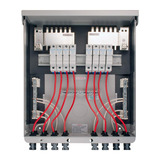
- Page 4 Step 13. Attach clips to 10 gauge stranded wire. White wire clips can be found in clip bag #9-250-1. Red wire clips can be found in #9- 249-1 Wiresizes are: White 4 ea @ 4 ½” 2 ea @ 7” 2 ea @ 6”...
- Page 5 Tighten down the retaining nut. Step 14. Step 16. Slide white wires and clips Slide the ends of the white wires through the bottom punch holes. into the busbars first and then the Slide the retaining nut onto the red wires into the fuse holders wire and tighten the clip down to and tighten down the retaining the chassis.
- Page 6 Step 17. Break out the blanks of the fuse holder covers #5-033-1 leaving the right one in place on the right cover and the left blank in place on the left cover. You will have to take a utility knife and trim the artifacts left the inside edges.
- Page 7 Step 18. Snap in the fuse holder covers into the deadfront making certain to have the left one on the left side and the right on the right. There are pegs on the back of each corner of the fuse holder cover that have to go into four holes on the deadfront.
- Page 8 Step 19. Attach the deadfront #5-032-1, placing the bottom end tabs into holes in the chassis and snap- ping in the top. Step 20. Make sure that the cover removal note is placed where it can be screwed down in between the cover and the chassis.
- Page 9 MNPV12 chassis is being used, the actual model of the unit is an MNPV8 using MC4 type clips. Also select which quarter of the year, in this case, the second quarter (Q2) and the last two digits of the year the unit was assembled, (11).
- Page 10 Step 22. Attach the cover to the chassis. Step 24. Step 23. Attach a MidNite Solar badge Screw down the cover using two #5-029-1 to the lower right of the #6-007-1 screws and two #6- cover. 017-1 lock washers. Make sure...
- Page 11 Step 25. Place unit in the plastic bag the unit came with.
- Page 12 Step 26. Place unit in the box with packing and the manual #10-053-1. Step 27. Place box label #10-054-1 on the box and tape the box up.
Need help?
Do you have a question about the MNPV8 and is the answer not in the manual?
Questions and answers