Table of Contents
Advertisement
Quick Links
Advertisement
Chapters
Table of Contents

Subscribe to Our Youtube Channel
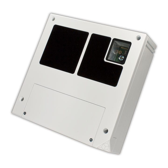
Related Manuals for Bluetechnix Argos 3D-P320


Summary of Contents for Bluetechnix Argos 3D-P320
- Page 1 Argos 3D-P320 Software User Manual Version 14...
- Page 2 A-1140 Vienna AUSTRIA office@bluetechnix.com www.bluetechnix.com Argos 3D-P320 – Software User Manual Document No.: 900-308 / A Publication date: February 2, 2016 Subject to change without notice. Errors excepted. This document is protected by copyright. All rights reserved. No part of this document may be reproduced or transmitted for any purpose in any form or by any means, electronically or mechanically, without expressly written permission by Bluetechnix.
-
Page 3: Table Of Contents
ToF Image Filters ........................27 4.3.1 Median Filter ........................28 4.3.2 Bilateral filter ........................28 4.3.3 Average filter ........................28 4.3.4 Sliding Average Filter ....................... 28 4.3.5 Frame Average Filter ......................28 ToF Image Enhancements ...................... 29 © Bluetechnix 2016... - Page 4 Over Temperature Protection ....................43 4.15 Color Sensor ........................43 4.15.1 UDP Color Sensor Stream ....................44 4.15.2 RTP Time Stamp ......................44 4.15.3 Color Sensor Control ....................... 44 4.16 Save Registers ........................45 4.17 Ethernet/IP Settings ......................45 © Bluetechnix 2016...
- Page 5 BltTofSuite ..........................63 Support ............................64 General Support ........................64 Software Downloads ....................... 64 Related Products ........................64 Camera Development Package ....................64 Document Revision History ......................65 Index ............................... 67 List of Figures and Tables ......................69 © Bluetechnix 2016...
- Page 6 Bluetechnix takes no liability for any damages and errors causing of the usage of this board. The user of this board is responsible by himself for the functionality of his application. He is allowed to use the board only if he has the qualification.
-
Page 7: General Information
Version 0.14 General Information This guide applies to the Argos 3D-P320 camera platform from Bluetechnix. Follow this guide chapter by chapter to set up and understand your product. If a section of this document only applies to certain camera parts, this is indicated at the beginning of the respective section. -
Page 8: Overview
Last change: 2 February 2016 Version 0.14 Overview The document describes the necessary steps and settings to work with the Argos 3D-P320 and describes the firmware dependent interfaces. This document applies to firmware version 0.12.0. For a hardware compatibility list please refer to our support site. -
Page 9: Interfacing
If you use this API, you need not be familiar with control and data interface in detail. Refer to chapter 7.1 for the BltTofApi. Control Interface The Argos 3D-P320 can be configured using a TCP/IP connection. For the control interface the Argos is listening to the following factory default IP settings: ... -
Page 10: Register Read
0x02 – 0x3D Table 3-2: Register read command frame Note 1): For the CRC16 calculation the CRC-CCITT is used (Polynom: 0x1021, start value: 0). Please ask the Bluetechnix support for an implementation example of the CRC-CCITT. Response frame Addr Field... -
Page 11: Result Codes
Note 1): For the CRC16 calculation the CRC-CCITT is used (Polynom: 0x1021, start value: 0). Please ask the Bluetechnix support for an implementation example of the CRC-CCITT. Note 2): For the CRC32 calculation the CRC-32 is used (Polynom: 0x04C11DB7, start value: 0xFFFFFFFF). Please ask the Bluetechnix support for an implementation example of the CRC-32. Flags Flags... -
Page 12: Table 3-6: Register Write Command Frame
Note 1): For the CRC16 calculation the CRC-CCITT is used (Polynom: 0x1021, start value: 0). Please ask the Bluetechnix support for an implementation example of the CRC-CCITT. Note 2): For the CRC32 calculation the CRC-32 is used (Polynom: 0x04C11DB7, start value: 0xFFFFFFFF). Please ask the Bluetechnix support for an implementation example of the CRC-32. Response frame Addr... -
Page 13: Reset
Header: 0x02 – 0x3D Table 3-7: Register write response frame Note 1): For the CRC16 calculation the CRC-CCITT is used (Polynom: 0x1021, start value: 0). Please ask the Bluetechnix support for an implementation example of the CRC-CCITT. Flags Flags Description... -
Page 14: Flash Update
– 0x3D Table 3-10: Reset response frame Note 1): For the CRC16 calculation the CRC-CCITT is used (Polynom: 0x1021, start value: 0). Please ask the Bluetechnix support for an implementation example of the CRC-CCITT. Flags Flags Description Currently no flags defined for this command... -
Page 15: Table 3-12: Flash Update Command Frame
Note 2): For the CRC32 calculation the CRC-32 is used (Polynom: 0x04C11DB7, start value: 0xFFFFFFFF). Please ask the Bluetechnix support for an implementation example of the CRC-32. Note 3): The DataCrc32 is mandatory, the appropriate flag must be set to 0. -
Page 16: Read Data From Flash
Software User Manual - Argos 3D-P320 Last change: 2 February 2016 Version 0.14 Note 1): For the CRC16 calculation the CRC-CCITT is used (Polynom: 0x1021, start value: 0). Please ask the Bluetechnix support for an implementation example of the CRC-CCITT. Subcommand SubCommand Description... -
Page 17: Alive
Note 2): For the CRC32 calculation the CRC-32 is used (Polynom: 0x04C11DB7, start value: 0xFFFFFFFF). Please ask the Bluetechnix support for an implementation example of the CRC-32. Note 3): The DataCrc32 is mandatory, the appropriate flag must be set to 0. -
Page 18: Table 3-20: Alive Command Frame
0x3D Table 3-20: Alive command frame Note 1): For the CRC16 calculation the CRC-CCITT is used (Polynom: 0x1021, start value: 0). Please ask the Bluetechnix support for an implementation example of the CRC-CCITT. Response frame Addr Field Type... -
Page 19: Data Interface
Software User Manual - Argos 3D-P320 Last change: 2 February 2016 Version 0.14 Flags Description Currently no flags defined for this command Table 3-22: Alive flag description Result codes: Please refer to Table 3-5. Data Interface A UDP stream delivers ToF and/or color data from the Argos. Each UDP packet contains a UDP streaming header and up to 1400 bytes of frame data (Ethernet, IP, and UDP headers are not shown in Figure 3-1). -
Page 20: Udp Streaming Header
ImageData Image data section Table 3-23: UDP packet header Note 1): For the CRC32 calculation the CRC-32 is used (Polynom: 0x04C11DB7, start value: 0xFFFFFFFF). Please ask the Bluetechnix support for an implementation example of the CRC-32. Flags Flags Description Bit 0... - Page 21 Software User Manual - Argos 3D-P320 Last change: 2 February 2016 Version 0.14 Addr Field Type Value Description 0x00 Reserved Uint16 0xFFFF 0x02 HeaderVersion Uint16 0x0003 Current header version (high byte first) 0x04 ImageWidth Uint16 0x00A0 Width of the image in pixels.
-
Page 22: Color Sensor Rtp Stream
Table 3-25: Frame header Note 1): For the CRC16 calculation the CRC-CCITT is used (Polynom: 0x1021, start value: 0). Please ask the Bluetechnix support for an implementation example of the CRC-CCITT. Color Sensor RTP Stream A UDP-based RTP stream with video data from the CMOS color image sensor is available in different resolutions and frame rates. -
Page 23: Web Server
The camera features 2 general-purpose inputs and 4 general-purpose outputs. Please see the register description in chapter 5.2 for more information. Status Indicator LED The Argos 3D-P320 camera features an RGB LED to indicate its internal status via different colors: Red: Camera is starting up ©... -
Page 24: Poe Power Control
(or both). Please see chapter 4.8 for details. The detected PoE class can be overridden by means of register PoEOverride. Secure Shell (SSH) Login The Argos 3D-P320 camera features an OpenSSH server listening to TCP port 22. Root account User account... -
Page 25: Debug Uart
Note Using the Debug UART is optional. The Argos 3D-P320 features a debug UART, which is the primary debug interface for the boot loader as well as the Linux kernel. The Debug UART is available via a micro-USB-connector, with a UART-to-USB converter behind. To be able to access the serial terminal via the Debug UART, you need an appropriate driver installed in your OS for the FTDI FT234 device. -
Page 26: Camera Features
Software User Manual - Argos 3D-P320 Last change: 2 February 2016 Version 0.14 Camera Features Basic Settings The Argos comes up according to the reset (default) values as described in the register description chapter (refer to chapter 6). Each camera has been pre-configured with a factory-default register map. -
Page 27: Tof Image Filters
Software User Manual - Argos 3D-P320 Last change: 2 February 2016 Version 0.14 Start Integration (ToF image capturing) Distance and amplitude calculation Raw distance? Corrections: Wiggling, FPPN, Distance Offset, Temperature Apply filter X Filtering Finished? Combine (HDR) XYZ Point Cloud... -
Page 28: Median Filter
Software User Manual - Argos 3D-P320 Last change: 2 February 2016 Version 0.14 ImgProcConfig2 (amplitude data) registers. Enabling more than one filter is possible but each added filter reduces the maximum achievable frame rate (as does the number of iterations). -
Page 29: Tof Image Enhancements
3D-P320 sets the pixel distance to the minimum value. The threshold is set via register ConfidenceThresHigh. Invalid pixels: The Argos 3D-P320 features an additional amplitude check called ACF (auto correlation function) Plausibility Check. It detects inconsistent pixels e.g. in case of fast movement in the scene. -
Page 30: Combine Sequences (Hdr)
The default coordinate system starts pixel numbering in the upper left corner of the pixel array, seen from the camera’s point of view. Also note the directions of X, Y, and Z coordinates (In XYZ image modes). Figure 4-2: Argos 3D-P320 Default Coordinate System Note If you are working with a BltTofApi library, or the BltTofSuite, the camera coordinate system is automatically converted. -
Page 31: Distances And Amplitudes
Software User Manual - Argos 3D-P320 Last change: 2 February 2016 Version 0.14 Alternatively, a 3D XYZ point cloud can be provided. Refer to chapter 4.4 for a description of the coordinate system of the camera. Color data from the CMOS image sensor can also be selected. -
Page 32: Distances, Amplitudes And Color
Software User Manual - Argos 3D-P320 Last change: 2 February 2016 Version 0.14 First Byte in Stream Lowbyte of Highbyte of Lowbyte of Highbyte of Lowbyte of Highbyte of Distance Distance Distance (Pixel 0) Distance (Pixel 0) Distance (Pixel 1) -
Page 33: Distances And Color
Software User Manual - Argos 3D-P320 Last change: 2 February 2016 Version 0.14 First Byte in Stream Lowbyte of Highbyte of Lowbyte of Highbyte of Lowbyte of Highbyte of Distance Distance Distance (Pixel 0) Distance (Pixel 0) Distance (Pixel 1) -
Page 34: Xyz Point Cloud
Software User Manual - Argos 3D-P320 Last change: 2 February 2016 Version 0.14 First Byte in Stream Lowbyte of Highbyte of Lowbyte of Highbyte of Lowbyte of Highbyte of Distance Distance Distance (Pixel 0) Distance (Pixel 0) Distance (Pixel 1) -
Page 35: Xyz Point Cloud And Amplitudes
Software User Manual - Argos 3D-P320 Last change: 2 February 2016 Version 0.14 First Byte in Stream Lowbyte of X- Highbyte of X- Lowbyte of X- Highbyte of X- Lowbyte of X- Highbyte of X- Coor. (Pixel 0) Coor. (Pixel 0) Coor. -
Page 36: Distances And Xyz Point Cloud
Software User Manual - Argos 3D-P320 Last change: 2 February 2016 Version 0.14 First Byte in Stream Lowbyte of X- Highbyte of X- Lowbyte of X- Highbyte of X- Lowbyte of X- Highbyte of X- Coor. (Pixel 0) Coor. (Pixel 0) Coor. -
Page 37: Coordinate And Amplitudes
Software User Manual - Argos 3D-P320 Last change: 2 February 2016 Version 0.14 4.6.7 X Coordinate and Amplitudes In this mode a single coordinate array, more specifically, the one belonging to the optical axis of the camera (X), is transferred in channel 0, as well as the amplitudes (channel 1). -
Page 38: Distances, Amplitudes, Confidences, And Color
Software User Manual - Argos 3D-P320 Last change: 2 February 2016 Version 0.14 First Byte in Stream Lowbyte of Highbyte of Lowbyte of Highbyte of Lowbyte of Highbyte of Distance Distance Distance (Pixel 0) Distance (Pixel 0) Distance (Pixel 1) -
Page 39: Color
Software User Manual - Argos 3D-P320 Last change: 2 February 2016 Version 0.14 4.6.14 Color This data format is only used for the UDP Color Sensor Stream (see chapter 4.15.1 for more information). This data format cannot be set via register ImageDataFormat. When this data format is transferred, field ImageFormat of the frame header (... -
Page 40: Sequencing
PoE constraints, Bit[10] of the Status register will be set. Sequencing The Argos 3D-P320 allows the configuration of up to 2 sequences on the TIM. These sequences are captured immediately after each other by the TIM. Each sequence can be configured with individual integration time and modulation frequency. -
Page 41: Tof Automatic Exposure Control (Aec)
4.15.3). 4.12 ToF Automatic Exposure Control (AEC) The Argos 3D-P320 provides an automatic exposure control feature which controls the integration time according to the currently observed scene. The AEC is disabled by default and must be enabled in the register Mode1. -
Page 42: Manual Frame Trigger
Software User Manual - Argos 3D-P320 Last change: 2 February 2016 Version 0.14 Figure 4-9: AEC weighing areas The AEC regulates the integration time of each sequence individually. AEC settings are common for all sequences. 4.13 Manual Frame Trigger There are two types of manual trigger. To enable the manual trigger, the video mode must be disabled in register Mode0, Bit[0]. -
Page 43: Over Temperature Protection
Request a new snapshot by setting the corresponding bit in register Mode0. (The bit is self-clearing.) 4.14 Over Temperature Protection The Argos 3D-P320 firmware has a built-in monitoring for over-temperature condition of the LIMs. If the LIM temperature exceeds 70°C, the camera will automatically stop illumination and streaming, until temperature is below 68°C. -
Page 44: Udp Color Sensor Stream
90 kHz, i.e., this timestamp increments by 90000 each second. The Argos 3D-P320 uses the same internal time base for this RTP timestamp and for the data stream timestamps (which are part of the frame header, see chapter 3.2). This is required for the receiver, in order to relate each received RTP frame and ToF frame on a time line. -
Page 45: Save Registers
CmdExec register. 4.18 Reset to Factory Default The Argos 3D-P320 can be reset to factory default settings by deleting the saved register map. This can be done by writing a dedicated value to the register CmdExec. Alternatively, a factory reset is executed via the camera’s reset signal. (Please consult the Hardware User Manual for details.) It must be active until the firmware is completely booted and the data stream is present. -
Page 46: Firmware Recovery
/mnt/logs/messages* files. Newest log data is contained in file messages. 4.21 Error Indication The Argos 3D-P320 indicates detected errors mainly in the Status register: Bit 3: Indicates a temperature measurement error on at least one LIM. The bit is automatically cleared if the error disappears. -
Page 47: Register Description
Software User Manual - Argos 3D-P320 Last change: 2 February 2016 Version 0.14 Register Description Note Some critical registers are password protected. To enable the functionality a specific value must be written to the CmdEnablePasswd register in advance to enable the functionality. - Page 48 Software User Manual - Argos 3D-P320 Last change: 2 February 2016 Version 0.14 Addr Register Name Default Description (hex) Value (hex) 0…V2.1 1…V2.2 2…V2.3 0008 FirmwareInfo Bit[0-5]: Non Functional Revision Bit[6-10]: Minor Revision Bit[11-15]: Major Revision 0009 ModulationFrequency 07D0 Modulation frequency index: 0…5 MHz...
- Page 49 Software User Manual - Argos 3D-P320 Last change: 2 February 2016 Version 0.14 Addr Register Name Default Description (hex) Value (hex) Bit[12]: 1…No FPPN Calibration data in NVM Bit[14]: 1…No Lens Calibration data in NVM 0022 CmdEnablePasswd 0000 Set a password for critical operations:...
-
Page 50: Registers For Gpio Control
Software User Manual - Argos 3D-P320 Last change: 2 February 2016 Version 0.14 Addr Register Name Default Description (hex) Value (hex) 003C TempCompGradient3Lim Factor ‘a’ of the temperature compensation function: y [mm] = a/100000 * x³ + b/10000 * x² +... -
Page 51: Registers For Color Image
Software User Manual - Argos 3D-P320 Last change: 2 February 2016 Version 0.14 Addr (hex) Register Name Default Value (hex) Description Bit[9]: … state of OUT_1 (R/W) Bit[10]: … state of OUT_2 (R/W) Bit[11]: … state of OUT_3 (R/W) Table 5-2: Registers for GPIO Control... -
Page 52: More General Registers
Software User Manual - Argos 3D-P320 Last change: 2 February 2016 Version 0.14 More General Registers Addr Register Name Default Description (hex) Value (hex) 00C1 DistOffset0 An offset for distance values when operating at modulation frequency with index 0 (5 MHz) -
Page 53: Registers For Sequencing
Software User Manual - Argos 3D-P320 Last change: 2 February 2016 Version 0.14 Addr Register Name Default Description (hex) Value (hex) Bit[1]: 1 … Initial register settings loaded 011B Ready 0000 and fully applied 011D Revision Camera revision Table 5-4: More General registers... -
Page 54: Registers For Automatic Exposure Control
Software User Manual - Argos 3D-P320 Last change: 2 February 2016 Version 0.14 Addr Register Name Default Description (hex) Value (hex) 100 - 30000 … Time for illumination pre-heating in microseconds 0152 IllPreheatingTimeSeq1 0000 Sequence 1 illumination preheating 0 … No pre-heating 100 - 30000 …... -
Page 55: Registers For Test Commands
Software User Manual - Argos 3D-P320 Last change: 2 February 2016 Version 0.14 Addr Register Name Default Description (hex) Value (hex) 01B5 AecKd 0000 Differential part of the auto exposure controller in percent Table 5-7: Registers for automatic exposure control... -
Page 56: Registers For Advanced Image Processing
Software User Manual - Argos 3D-P320 Last change: 2 February 2016 Version 0.14 Addr Register Name Default Description (hex) Value (hex) Bit[7]: 1…enable FPPN compensation for Distance Image Bit[10]: 1…enable FrameAverage Filter for Distance Image Bit[11]: 1…enable temperature compensation for Distance Image Bit[13]: 1…enable offsets via registers... - Page 57 Software User Manual - Argos 3D-P320 Last change: 2 February 2016 Version 0.14 Addr Register Name Default Description (hex) Value (hex) Writing this register has no immediate effect. 0243 Eth0Mac0 Byte 1 and byte 0 (=Low byte) of MAC address Writing this register will update the network configuration with the new MAC address.
-
Page 58: Table 5-11: Registers For Ethernet Configuration
Software User Manual - Argos 3D-P320 Last change: 2 February 2016 Version 0.14 Addr Register Name Default Description (hex) Value (hex) Writing this register will update the 2D camera stream address. 0254 Eth0Udp2dStreamPort 2714 UDP port for 2D video stream... -
Page 59: Firmware History
[Usability] Change pixel invalidation priority: INVALID, then OVER/UNDEREXPOSED. Image Header was extended due to new image data formats. Please contact Bluetechnix support for information how to store factory defaults. 0.4.1 Apr 2015 [Unintended Behaviour] Change order of applying filters ... - Page 60 Software User Manual - Argos 3D-P320 Last change: 2 February 2016 Version 0.14 Firmware Status Release Changes Version date New registers Lim1Status and Lim2Status [Stability] Make 2D capturing more fault-tolerant [Feature Request] Temperature compensation: Change x^3 factor to 1/100000 ...
- Page 61 Add register 0x0007 which publishes PCB revision of the camera Fix problem with reading the temperature from the TIM 0.7.0 Add an independent color sensor data stream over Bluetechnix Grade 2015 UDP data protocol Chapters 4.6.14, 4.15.1, 5.3, 5.12 ...
-
Page 62: Anomalies
0.3.1 2014 11 13 If your Argos 3D-P320 was delivered with firmware version 0.2.2 originally, factory default reset resets DistOffsetX registers to zero. Please contact Bluetechnix support for instructions how to configure factory default settings. -
Page 63: Software
In order to create a common interface for our products we define the interfaces between a ToF device and an application. The main part of this model is the BltTofApi which is written in C for platform independency. The library which provides this API for Ethernet-based devices as the Argos 3D-P320 is the BtaEthLib (BltTofApi Ethernet Library). -
Page 64: Support
Camera Development Package The camera offers the possibility to bring your own application onto the Argos 3D-P320. The Argos 3D-P320 is based on an embedded ARM Linux system based on the i.MX6 Quad-core processor from Freescale Inc. Please contact Bluetechnix support for more information. -
Page 65: Document Revision History
Software User Manual - Argos 3D-P320 Last change: 2 February 2016 Version 0.14 Document Revision History Version Date Document Revision 2014 08 01 Initial version of the document 2014 11 13 Added firmware changes from 0.2.2 to 0.3.1 firmware version (Chapter 6.1) Updated register description (Chapters 5.1, 5.2) -
Page 66: Table 9-1: Revision History
Software User Manual - Argos 3D-P320 Last change: 2 February 2016 Version 0.14 Version Date Document Revision 2015 09 23 Updated description of registers 0x1EB and 0x1ED in chapter 5.10 2015 09 30 Added firmware V0.8.0 description to chapter 6.1 Updated chapter 5.4 (New register) -
Page 67: A Index
Software User Manual - Argos 3D-P320 Last change: 2 February 2016 Version 0.14 A Index Frame Average ............29 Median ..............29 Registers ..............57 Anomalies ..............64 Sliding Average ............29 Automatic Exposure Control ......... 42, 56 Firmware Recovery ............. 47 Firmware Update ........... - Page 68 Software User Manual - Argos 3D-P320 Last change: 2 February 2016 Version 0.14 Support ............... 66 Over Temperature Protection ........44 Temperature compensation ........30 Test Commands .............. 56 Pixel orientation............32 Image mode ............38 Power over Ethernet ............ 25 Time Stamp Pre-heating............
-
Page 69: B List Of Figures And Tables
Figure 3-1: UDP streaming data format ......................19 Figure 4-1: Image processing flow ........................27 Figure 4-2: Argos 3D-P320 Default Coordinate System ................... 30 Figure 4-3: Data stream of Distance and Amplitude data ................. 32 Figure 4-4: Data stream of Distance, Amplitude, RGB565 Color data ............. 33 Figure 4-5: Data stream of distance and RGB565 data .................. - Page 70 Table 5-9: Registers for device update ......................55 Table 5-10: Register for filter configuration ....................... 56 Table 5-11: Registers for Ethernet configuration ....................58 Table 6-1: Overview Argos 3D-P320 firmware changes ................... 62 Table 6-2: Firmware anomalies ......................... 62 Table 9-1: Revision history ..........................66 ©...
Need help?
Do you have a question about the Argos 3D-P320 and is the answer not in the manual?
Questions and answers