
Subscribe to Our Youtube Channel
Related Manuals for GEDA 200Z

Summary of Contents for GEDA 200Z
- Page 1 Assembly and Operating Manual Rack and pinion hoist For loads Original operating manual...
- Page 3 Rack and pinion hoist Assembly and Operating Instructions 3 / 100 BL108 GB Edition 03.2018 Rev. 02...
- Page 4 Rack and pinion hoist Assembly and Operating Instructions 4 / 100 BL108 GB Edition 03.2018 Rev. 02...
-
Page 5: Table Of Contents
Rack and pinion hoist Table of Contents: Section Page General information ........................... 7 Information about the instruction manual ..................7 Information about the machine ....................8 Name and address of the manufacturer ..................9 Notes about the author and industrial property rights ..............9 Instructions for the operating company .................. - Page 6 Rack and pinion hoist 6.3.1 Loading gate ........................57 6.3.2 Turning lever ........................57 6.3.3 “ECO” landing level safety gate ..................58 Operating the hoist ........................59 Emergency shutdown ........................ 60 Interrupting work – end of work ....................60 Dismantling (disassembly) ......................61 Maintenance and cleaning ......................
-
Page 7: General Information
Rack and pinion hoist General information Information about the instruction manual This operating manual is an essential aid to operating the machine successfully and hazard-free. This operating manual contains important instructions on how to operate the machine safely, correctly and efficiently. Compliance with these instructions helps to avoid hazards and increases the reliability and service life of the machine. -
Page 8: Information About The Machine
Rack and pinion hoist The structural elements in this operating manual appear as follows and have the following meaning Health and safety symbol This symbol is found next to all safety instructions where there is a risk of injury or a fatality. Observe these instructions and be very cautious! Warning level Consequence Probability... -
Page 9: Name And Address Of The Manufacturer
Violations are an offence and incur an obligation to pay compensation. All rights to exercise industrial property rights are reserved by GEDA. Assembly and Operating Instructions 9 / 100... -
Page 10: Instructions For The Operating Company
Any replacement and wear parts that are used must correspond to the technical requirements stipulated by GEDA. This is ensured with original replacement parts. Only employ qualified and/or trained personnel for the tasks described in this manual. -
Page 11: Intended Use
Rack and pinion hoist Intended use The GEDA 200 Z rack and pinion hoist is a construction hoist that is temporarily erected and • which is intended exclusively for putting up scaffolding and as additional equipment (landing level safety gates) for transporting items and materials during construction work. -
Page 12: Requirements Of Assembly Personnel
Rack and pinion hoist 1.6.1 Requirements of assembly personnel The machine must only be assembled, operated and maintained by competent persons who, based on their training or knowledge and practical experience, can ensure correct handling and who are instructed about the risks associated with the construction hoist. These persons must be appointed to the tasks of installation, dismantling and maintenance by the operating company. -
Page 13: General Safety Information
Rack and pinion hoist General safety information The machine has been designed and built according to the latest standards of technology and recognised safety-related rules. Nevertheless, hazards for personnel or third parties and/or damage to machinery and other tangible assets can occur during use, e.g. if the machine: Is operated by untrained or uninstructed personnel, −... -
Page 14: Safety Instructions For Operating Personnel
Rack and pinion hoist Safety instructions for operating personnel The operating manual must be within reach at all times at the location where the machine is used. The machine must only be used when fully serviceable, as well as in accordance with the intended use, in a safety conscious manner aware of the hazards and whilst observing the operating manual! In particular rectify faults immediately that could impair safety! -
Page 15: Safety Instructions For Transport
Rack and pinion hoist Safety instructions for transport Immediately report transport damage and/or missing parts to the supplier. During transport work, wear a safety helmet, safety shoes and safety gloves! Never step under suspended loads! Only use appropriate, standardised and tested lifting gear, forklifts, cranes) and sling gear (round slings, lifting straps, sling ropes, chains) for transport at the assembly site. -
Page 16: Safety Instructions For Operation
Rack and pinion hoist Safety instructions for operation Only operate the machine, under consideration of the operating manual, when it is fully serviceable and in a safety and hazard conscious manner. If work is interrupted, switch off the machine at the main switch and secure it with a padlock against switching on. -
Page 17: Safety Instructions For Servicing, Maintenance And Troubleshooting
Rack and pinion hoist Safety instructions for servicing, maintenance and troubleshooting Before they start work, operating personnel must be informed about how to carry out special tasks and maintenance tasks. Deadlines that are stipulated or stated in the operating manual for recurring tests/inspections must be adhered to. - Page 18 Rack and pinion hoist If it is necessary to remove safety devices during servicing and repairs, the safety devices must be installed and checked immediately after completion of servicing and repair tasks! Do not make any changes, additions or modifications to the machine. This also applies to the installation and adjustment of safety devices such as limit switches.
-
Page 19: Safety Whilst Working On The Electrics
Rack and pinion hoist Safety whilst working on the electrics If there are faults on the electrical system of the machine, it must be shut down immediately using the main switch and secured with a lock or the mains plug must be removed! Work on the electrical equipment of the machine must only be carried out by qualified electricians working in accordance to electrical engineering regulations! Only professional electricians may access the... -
Page 20: Technical Description
Rack and pinion hoist Technical description Description of function The GEDA 200 Z is a vertically installed rack and pinion hoist which is used exclusively for transporting scaffold parts, objects and construction material. • The base unit can be extended with 1.0 m and 2.0 m long ladder sections up to a max. -
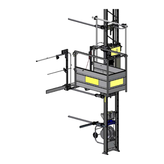
Page 21: Machine Equipment
Rack and pinion hoist Machine equipment Foot section with base mast Spring-loaded cable drum Foot section anchoring Assembly protective clamp Load platform Loading ramp Rail bracket with fastening tube Ladder section Limit switch bracket for up or down limit switch 10 = Landing-level safety door “ECO”... - Page 22 Rack and pinion hoist 3 = Spring-loaded cable drum 11 = Drive motor 12 = Switch box, foot section 13 = Socket (grey) for manual control 14 = Manual control (ground control) Assembly protection bar A protection bar (15) which immediately stops the platform travelling in either direction when operated is mounted on the upper...
-
Page 23: Operating And Control Elements
Rack and pinion hoist 3.2.1 Operating and control elements Main switch On the foot section switch box Serves the purpose of switching On/Off at the start/end of work. In the event of malfunctions or maintenance/repair work and at the end of work the master switch must be secured with a padlock to prevent it being switched on. - Page 24 Rack and pinion hoist Platform access / Loading ramp The interlock hook (1) must engage twice. Travelling in the load platform is permitted to carry out assembly and maintenance tasks by persons competent for this task. Closing Hook in the front side fall protection (2) on the opposite platform railing.
-
Page 25: Equipment As Accessories
Rack and pinion hoist Equipment as accessories 3.3.1 Retainer for scaffolding Loads that are taller than the load platform (e.g. scaffolding tubes) can be transported securely without falling using this holder (1). The 1½" tubes and scaffolding couplings are not included in the scope of delivery. -
Page 26: Landing Level Control
Rack and pinion hoist 3.3.2 Landing level control To simultaneously transport material to several landings, a landing control is offered as an accessory, up to four landings can be specifically moved to. 1 = Landing control 2 = Limit switch, approach area 3 = Landing limit switch ... - Page 27 Rack and pinion hoist At the required stop position, install the limit switch (3) on the right ladder rail (viewed towards the building). The limit switch roller must point to the rack. Distance from the landing floor to the limit switch roller approx. 1.17 m ...
-
Page 28: Small On-Site Main Cabinet
Rack and pinion hoist Operating the landing control Set the selector switch (7) to “1”. When ascending, the load platform stops at the 1st landing limit switch. Set the selector switch (7) to “2”. When ascending, the load platform stops at the 2nd landing limit switch. -
Page 29: Technical Data
Rack and pinion hoist Technical Data 3.4.1 Operating and environmental conditions The machine must only be operated when the following operating and environmental conditions are satisfied: Temperature range minimum -20°C maximum +40°C Wind speed Operation/maintenance/servicing maximum 72 km/h Installation maximum 45 km/h The height-dependent variation in wind speed must be taken into account. -
Page 30: Speeds
Rack and pinion hoist 3.4.2 Speeds Lifting speed Construction hoist approx. 25 m/min. Safety gear Triggering speed (V 44 m / min. 3.4.3 Electrics Base unit Operating voltage 230 V / 50 Hz / 3 x 16 A / 1 Ph Protection class IP 54 (NEMA 3) Drive... -
Page 31: Ladder Section
(GEDA 200 Z) COMBILIFT 250 Z) For reasons of static strength, only ladder sections with diagonal reinforcement welded in can be used for the GEDA 200 Z! Must not be used with the GEDA 200 Z! Ladder section 1 m... -
Page 32: Load Capacity, Dimensions And Weights
(1½" pipe constructed on site) Wall bracket 6 kg (only in conjunction with rail bracket) Length of lines 200Z (37 m assembly height) 39.3 m 200Z (41 m assembly height) 45.3 m Assembly and Operating Instructions 32 / 100 BL108 GB Edition 03.2018 Rev. 02... -
Page 33: Anchoring And Spatial Requirement
Rack and pinion hoist Anchoring and spatial requirement Assembly and Operating Instructions 33 / 100 BL108 GB Edition 03.2018 Rev. 02... -
Page 34: Anchoring Forces
Rack and pinion hoist 3.5.1 Anchoring forces For the anchoring forces, refer to the following tables. Details are given of the peak forces occurring for the assembly geometry shown; they do not include any safety factors. The anchoring forces apply for all the wind regions in Europe. Extreme locations may require exceptions. - Page 35 Rack and pinion hoist Assembly in front of a wall Anchoring distance V = Load capacity = max. 200kg Anchoring forces with maximum track projection 1.08 kN 3.33 kN The values in the table apply for each anchorage point Assembly and Operating Instructions 35 / 100 BL108 GB Edition 03.2018 Rev.
- Page 36 Rack and pinion hoist Assembly in front of a scaffolding Anchoring distance V = Load capacity = max. 200kg Barrier on building side and identification Scaffold bay depth = 0.7 m Anchoring forces with maximum track projection 2.94 kN 1.50 kN The values in the table apply for each anchorage point Scaffold bay depth = 1.0 m Anchoring forces with maximum track projection...
-
Page 37: Requirements Of The Installation Site
Rack and pinion hoist Requirements of the installation site 3.6.1 Foundation • The foundation must be horizontal and have sufficient load bearing capacity. The foundation must be compacted according to the ground load − [kN/m²] (refer to assembly height). • Depending on the assembly height, for example, wooden planks or steel sheeting, can be used as load distributing base supports. -
Page 38: Mains Connection
Rack and pinion hoist 3.6.3 Mains connection A building site main cabinet (according to IEC 60439-4:2004) with fuse protection of the supply point with min. fusing of 16A slow-to-blow is required on site. 200 Z with 230 V drive Supply point: 230V / 50Hz −... -
Page 39: Transport
Rack and pinion hoist Transport Transportation of the hoist only to be carried out by competent persons. Inspection on receiving the hoist • Check the shipment for transport damage and for completeness according to the purchase order. • Immediately notify the freight carrier (haulage company) and dealer of any transport damage. -
Page 40: Installation
• At loading positions from 2.0 m height, protection to prevent persons from falling must be provided (only use original GEDA landing-level safety doors). • Observe the load capacity of the hoist. -
Page 41: Assembly Procedure
Rack and pinion hoist • During assembly, never do the following from the load platform: reach or lean into the travel path during travel. allow parts to project into the travel path during ascent/descent. stand on the load. exit the load platform to climb onto the ladder or building. Assembly procedure Fundamentally, assembly is carried out in accordance with the following procedure. -
Page 42: Assembling The Base Unit
Rack and pinion hoist Assembling the base unit • The machine must be installed and deployed only vertically! The base unit must be aligned parallel to the building or scaffold. The distance between the ladder track and the vertical scaffold post −... -
Page 43: Install The Rail Bracket And Anchor
Rack and pinion hoist 5.3.1 Install the rail bracket and anchor WARNING Danger to life Danger to life through fracture of the mast and falling load platform. Vertical distances of the ladder ties - First ladder tie at a height of 1.8 m. - Next ladder tie at a height of 4.0 m. - Page 44 Rack and pinion hoist Anchoring to a scaffold If the hoist is erected against scaffolding it must be anchored to the building. It can also be anchored directly to the scaffolding if the scaffolding has been designed for the additional load (see anchoring forces). •...
- Page 45 Rack and pinion hoist Anchoring against a wall • Install the rail bracket (1) into the ladder section as described and fully tighten. Using the scaffold clamps (3), loosely attach the wall bracket (2) to the rail bracket and attach to the wall with bolts and plugs or anchor with through bolts.
-
Page 46: Fitting The Turning Unit
Rack and pinion hoist 5.3.2 Fitting the turning unit The swivelling frame can be fitted hinged to the left or the right on the mountings (1) on the trolley. The swivelling frame can be adapted to the trolley side required by rotating the swivel lever mounting. - Page 47 Rack and pinion hoist Fitting the swivelling frame on the left-hand side of the trolley • Prepare the swivelling frame for the left-hand side of the trolley Fit the turning lever support (2) onto the turning unit (4) according to the drawing using the three M10 x 16 bolts and spring washers (3).
-
Page 48: Assembling The Platform
Rack and pinion hoist 5.3.3 Assembling the platform Insert the platform (1) on the rectangular tubes (2) of the turning unit and push towards the trolley until you hear it engage with the interlock lever (3) on the underside of the load platform. ... -
Page 49: Installing The Ladder Sections
Rack and pinion hoist Installing the ladder sections The hoist can be erected from the platform. However, the following points must be observed: The load platform is also intended for assembly. − Use fall protection on the front side. − The hoist must only be operated from the load platform (use an −... - Page 50 Rack and pinion hoist Hold the securing lever (4) down briefly with your left thumb until the locking lever (3) has moved slightly in the direction of the arrow. Reach around the ladder section and use your right hand to push the locking lever (3) from the rear in the direction of the arrow until it latches.
- Page 51 Rack and pinion hoist DANGER Danger to life All interlock levers of the ladder sections must be closed (pointing vertically downwards), except for the top one (last). This must remain open. It acts as overrun protection for the ladder end during operation! ...
-
Page 52: Limit Switch, Approach Bar
Rack and pinion hoist 5.4.1 Limit switch, approach bar In operation, the ladder end may only be travelled to a maximum of 3 m above the topmost anchorage point. There are two possibilities for ensuring this: First option • The topmost lock is open and is located a max. of 3 m above the last anchor. -
Page 53: Securing Loading And Unloading Points
Rack and pinion hoist Securing loading and unloading points To prevent persons falling, fall protection must be installed at all loading and unloading points where there is a risk of falling from a height of more than 2 m. The landing-level safety door “ECO”, together with the loading ramp on the load platform, provides safe transfer to the building or scaffold. -
Page 54: Check After Assembly And Before Each Operation
• Carry out a drop test to check the function of the safety gear. (Refer to Chapter 8.5.2). Check the GEDA 200 Z according to national regulations after assembly and before initial commissioning, as well as after each assembly at a new construction site or any other new site. -
Page 55: Operation
Rack and pinion hoist Operation The GEDA 200 Z may only be operated by a qualified person appointed by the operating company. This person must be familiar with the operating manual, have sufficient experience and be informed about the risks involved in handling the hoisting equipment. -
Page 56: Safety Check Before Starting Work
Rack and pinion hoist The brake release lever must never be used to lower the load platform during operation. It is intended only for use in emergencies (refer to Chapter 9.1.2). Safety check before starting work Perform a test run with an empty load platform to ensure that the entire travel path of the platform is clear. -
Page 57: Using The Platform Access Point
Rack and pinion hoist Using the platform access point 6.3.1 Loading gate Open Unlatch the loading ramp (1) at the interlock hook (2) and lower the ramp. Close Raise the loading ramp (1) and press against the load platform until the interlock hook (2) engages twice. -
Page 58: Eco" Landing Level Safety Gate
Rack and pinion hoist 6.3.3 “ECO” landing level safety gate • Turn the load platform towards the landing level safety gate. Open the landing level safety door Take the key (1) out of the bag (2) on the load platform. ... -
Page 59: Operating The Hoist
Rack and pinion hoist Operating the hoist The platform must be turned towards the trolley and latched into place. The loading ramp must be closed. • Rotate the main switch to the position “I”. • Unlock the EMERGENCY STOP button (1) on the manual control. -
Page 60: Emergency Shutdown
Rack and pinion hoist Emergency shutdown In situations that present a risk to operating personnel or the hoist, the load platform can be shutdown by pressing the EMERGENCY STOP button. There is an EMERGENCY STOP button on the manual control −... -
Page 61: Dismantling (Disassembly)
Rack and pinion hoist Dismantling (disassembly) The rack and pinion hoist must be disassembled according to the assembly and operating manual under supervision by a qualified person specifically appointed by the operating company! Assembly personnel, refer to Chapter 1.6.1 For disassembly, the same regulations and safety instructions are applicable as described in Chapter 5. -
Page 62: Maintenance And Cleaning
Servicing tasks must only be carried out by competent persons. Immediately report any changes or malfunctions to the company management or their authorised representative. If necessary, shut down and secure the GEDA 200 Z immediately. WARNING Before all maintenance / servicing tasks, read the cmpl. manual. -
Page 63: Maintenance Schedule
Rack and pinion hoist Maintenance schedule Tasks to be carried out Check the braking distance Check the gear rack and drive pinion for lubrication and wear Check the trailing cable, mains supply cable and control lines for damage. Visual inspection of all defect devices and limit switches Check the rack and drive pinion for wear Check that the ladder interlocking, limit switch approach bar and ladder ties/bolts are securely attached to the ladder and... -
Page 64: Checks
Rack and pinion hoist Checks Inspections prior to commissioning, recurring inspections and intermediate inspections must be carried out according to national regulations. During the checks, the condition, presence and function of all safety-related features of the machine are checked using appropriate procedures. -
Page 65: Checks Before Initial Commissioning
The spring-loaded cable drum must not be contaminated (free of − snow and ice in winter). Keep the work area around the GEDA 200 Z clear and clean. − For checks after each installation → refer to Chapter 5.6 8.2.4 Recurring checks ... -
Page 66: Checks After Extreme Weather Conditions
Rack and pinion hoist 8.2.5 Checks after extreme weather conditions Special check after temperatures of – 40 °C [-40 °F] NOTE: If it is unclear if the temperature was less than – 40 °C [-40 °F], follow procedures as if this temperature had been reached when starting up the machine again. -
Page 67: Replenishment And Inspection Tasks
Replenishment and Inspection Tasks 8.3.1 Lubrication of the gear rack / drive pinion • Lubricate gear racks or spray with adhesive lubricant. Recommended lubricant: GEDA Special spray Item No. 02524 − Grease cartridge Item No. 13893 for grease gun − ... -
Page 68: Check The Ladder Interlocks And Bolted Connections
Rack and pinion hoist 8.3.4 Check the ladder interlocks and bolted connections • Check the ladder interlock All interlock levers of the ladder sections must be closed (pointing − vertically downwards), except for the top one (last). This must remain open. -
Page 69: Checking For Wear
Rack and pinion hoist Checking for wear WARNING Danger of injury from components failing Parts must be replaced immediately if the specified wear limits are exceeded. Machine operation is prohibited until the parts have been replaced. All parts must also be checked for damage (deformation, cracks, cavities, etc.). -
Page 70: Tracks Rollers
Rack and pinion hoist 8.4.3 Tracks rollers Track roller (white) Item No. 16921 Wear limit (diameter) Ø min. Ø normal 47.5 mm -0.20 Also check the play and condition of the bearing. Track roller with chamfer (black) Item No. 03067 Wear limit (diameter) Ø... - Page 71 Rack and pinion hoist Replace the track roller The track roller can be replaced without moving the trolley out of the ladder track. Raise the car above the base unit. Switch off the main switch and secure with a padlock against switching on! DANGER Danger to life...
-
Page 72: Motor Brake
Rack and pinion hoist 8.4.4 Motor brake Check the braking distance Carry out a test run with the hoist loaded and check whether the motor brake overtravel in downwards travel is exceeded (trolley or platform must not come to rest on the buffers). Adjust the motor brake The working air gap is measured in the braking position between the anchor plate and the magnetic body. - Page 73 Rack and pinion hoist Readjustment: Switch off drive power supply. Unscrew the manual release bolts, loosen the fan guard fastening screws and remove fan guard. Pull dust protection ring out of the slot in the magnetic body and put over the end plate.
-
Page 74: Function Checks
Rack and pinion hoist Function checks 8.5.1 Check the overload triggering Check the setting of the overload triggering. Evenly load the load platform (without accessories) with test weights (236 kg 2%). Activate the Up button The load platform must not move, the red control light (1) on the trolley switch box must illuminate and an alarm signal must sound. -
Page 75: Test The Safety Gear
Rack and pinion hoist 8.5.2 Test the safety gear WARNING Danger of injury from components failing The drop test must only be carried out by a qualified person, who has been specifically appointed by the operating company and who is able to evaluate the risks and assess the safe condition of the safety gear based on his or her training, knowledge and practical experience. - Page 76 Rack and pinion hoist Safety gear passed Further travel is not possible once the safety gear has been triggered. Resetting the safety gear Loosen the two central opposing locking screws (1). Turn the driver disc (2) clockwise until the actuating lever (3) for the limit switch engages in the groove in the driver disc (2).
- Page 77 Rack and pinion hoist Check safety gear for damage If any damage is identified on the safety gear, it must be immediately replaced. Machine operation is prohibited until it is repaired. WARNING Risk of injury Repairs to the safety gear must only be carried out by the manufacturer.
-
Page 78: Safety Gear Replacement
Rack and pinion hoist 8.5.3 Safety gear replacement GEDA safety gears must be replaced with GEDA safety gear in accordance with the following time intervals (safety gear exchange units). Safety gears replacement interval*) GEDA rack and pinion hoists with explosion every 3 years protection (ATEX, NEC, …) - Page 79 Rack and pinion hoist Remove the safety gear Raise the car above the base unit. Main switch switched off. DANGER Danger to life Due to the machine being switched on during maintenance/servicing tasks. Secure the main switch with a lock against switching on. ...
- Page 80 Rack and pinion hoist Remove the attachment screws (4) for the safety brake. Guide the safety gear out of the trolley. Installation the safety gear Guide the safety gear on the trolley. Install the bearing shells with bearing (3) on both sides. ...
- Page 81 Rack and pinion hoist Check The shaft flyweight (7) must be axially flush with the arrestor hook (8) of the safety brake. Install bearing shells with bearings (3) on both sides. Push the sleeve (9) over the shaft on both ends and fix in place using two threaded pins (9A).
-
Page 82: Malfunctions - Diagnosis - Repair
Rack and pinion hoist Malfunctions - Diagnosis – Repair WARNING Only have troubleshooting and fault elimination carried out by authorised personnel trained especially for this kind of work. Before troubleshooting, run the platform down and unload, if possible! Immediately discontinue operation if faults occur that endanger operational safety! DANGER Electric shock... -
Page 83: Fault Table
Rack and pinion hoist Fault table In the following table you will find potential faults and the appropriate remedial action. Fault Cause Remedial action Load platform does Fuses in the building site Check/correction not move main cabinet okay Mains plug disconnected Connect mains plug Main switch off Switch on the main switch... -
Page 84: Motor Is Not Producing Full Output
Rack and pinion hoist 9.1.1 Motor is not producing full output Voltage drop of more than 10% of the rated voltage. − Select a supply cable with a larger cross-section. − If overloaded, the integrated thermal switch turns off the control −... -
Page 85: Overload Warning Device Has Triggered
Rack and pinion hoist 9.1.4 Overload warning device has triggered The hoist is equipped with an overload warning device which prevents the load platform from starting when it is overloaded. If the load platform is overloaded, a red control light (1) illuminates on the trolley switch box and a alarm signal sounds. -
Page 86: Retrieving The Platform
Rack and pinion hoist Retrieving the platform Retrieval may become necessary if, e.g. • there is no mains voltage. • there are malfunctions in the electrical system. • the drive has failed. • the safety gear has triggered. WARNING If the rescuers do not feel sufficiently secure and qualified to organise and carry out the rescue, additional relevant authorities must also be notified (fire service, technical rescue services, works security). -
Page 87: Rescue Action Plan
Rack and pinion hoist 9.2.2 Rescue action plan Action 1: Checking the EMERGENCY STOP button. This could have been accidentally actuated. Unlock the EMERGENCY STOP button (1) (refer to Chapter 6.5) Press BUTTON UP (2) or DOWN (3) to continue travel. - Page 88 Rack and pinion hoist If the brake is released too much then the load platform will build up an excessive speed and the safety gear will engage! If the safety gear has engaged once, it will not be possible to progress any further without raising the load platform or resetting the safety gear.
-
Page 89: Repair
The nameplate is located on the trolley of the base unit. Spare parts must conform to the technical specifications of the manufacturer! Only use original spare parts from GEDA. For service or repair tasks, please contact our customer service department: Sales and customer service addresses, refer to Chapter 1.3... -
Page 90: Appendix A Summary Of Instruction Notices
Rack and pinion hoist Appendix A Summary of instruction notices Item No. 05242 Item No. 14657 Item No. 33697 (trolley) (trolley) (all switch boxes) Item No. 14656 Item No. 14523 (Manual control) (trolley switch box) Item No:30542 (trolley) Assembly and Operating Instructions 90 / 100 BL108 GB Edition 03.2018 Rev. -
Page 91: Appendix B Test Documentation
Rack and pinion hoist Appendix B Test Documentation Documentation for regular check in accordance with the maintenance schedule unplanned check after unusual events Name: Serial number: Year of manufacture: Works number: The machine was checked on______________. As a result none ... - Page 92 Rack and pinion hoist Documentation for regular check in accordance with the maintenance schedule unplanned check after unusual events Name: Serial number: Year of manufacture: Works number: The machine was checked on______________. As a result none the following ...
- Page 93 Rack and pinion hoist Documentation for regular check in accordance with the maintenance schedule unplanned check after unusual events Name: Serial number: Year of manufacture: Works number: The machine was checked on______________. As a result none the following ...
- Page 94 Rack and pinion hoist Documentation for regular check in accordance with the maintenance schedule unplanned check after unusual events Name: Serial number: Year of manufacture: Works number: The machine was checked on______________. As a result none the following ...
- Page 95 Rack and pinion hoist Documentation for regular check in accordance with the maintenance schedule unplanned check after unusual events Name: Serial number: Year of manufacture: Works number: The machine was checked on______________. As a result none the following ...
- Page 96 Rack and pinion hoist Documentation for regular check in accordance with the maintenance schedule unplanned check after unusual events Name: Serial number: Year of manufacture: Works number: The machine was checked on______________. As a result none the following ...
- Page 97 Rack and pinion hoist Documentation for regular check in accordance with the maintenance schedule unplanned check after unusual events Name: Serial number: Year of manufacture: Works number: The machine was checked on______________. As a result none the following ...
- Page 98 Rack and pinion hoist Space for notices Notice entered Name: / Date Position Assembly and Operating Instructions 98 / 100 BL108 GB Edition 03.2018 Rev. 02...
- Page 99 Rack and pinion hoist Space for notices Notice entered Name: / Date Position Assembly and Operating Instructions 99 / 100 BL108 GB Edition 03.2018 Rev. 02...
- Page 100 GEDA-Dechentreiter GmbH & Co. KG Mertinger Strasse 60 86663 Asbach-Bäumenheim Tel.: +49 (0)9 06 / 98 09-0 Fax: +49 (0)9 06 / 98 09-50 E-Mail: info@geda.de Web: www.geda.de BL108 GB Edition 03/2018 Rev. 02...
Need help?
Do you have a question about the 200Z and is the answer not in the manual?
Questions and answers