Table of Contents
Advertisement
Available languages
Available languages
ORIGIN 21 and logo design are trademarks or
registered trademarks of LF, LLC. All rights reserved.
ATTACH YOUR RECEIPT HERE
Serial Number
Questions, problems, missing parts? Before returning to your retailer, call our
customer service department at 1-888-251-1026, 8 a.m. - 8 p.m., EST, Monday - Sunday.
You could also contact us at partsplus@lowes.com or visit www.lowespartsplus.com.
RR21016
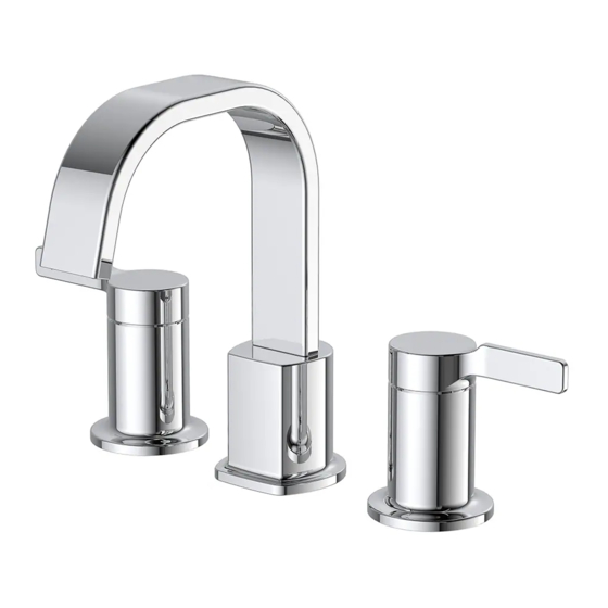
WIDESPREAD BATH
Purchase Date
1
ITEM #3782734
#3782735
#3782736
#3782737
FAUCET
MODEL #FW0AC015CP
#FW0AC015SP
#FW0AC015BL
#FW0AC015CZ
Español p. 13
Advertisement
Table of Contents

Subscribe to Our Youtube Channel
Related Manuals for LF ORIGIN 21 FW0AC015CP


Summary of Contents for LF ORIGIN 21 FW0AC015CP
- Page 1 ITEM #3782734 #3782735 #3782736 #3782737 ORIGIN 21 and logo design are trademarks or WIDESPREAD BATH registered trademarks of LF, LLC. All rights reserved. FAUCET MODEL #FW0AC015CP #FW0AC015SP #FW0AC015BL #FW0AC015CZ Español p. 13 ATTACH YOUR RECEIPT HERE Serial Number Purchase Date Questions, problems, missing parts? Before returning to your retailer, call our customer service department at 1-888-251-1026, 8 a.m.
-
Page 2: Package Contents
PACKAGE CONTENTS PART DESCRIPTION QUANTITY Hot Handle Rubber Washer Metal Washer Guide Washer Rubber Spacer Metal Spacer Lock Nut Faucet Connecting Hose Faucet Body Cold Handle Aerator DRAIN ASSEMBLY COMPONENTS Main Plunger Rubber Washer Lock Nut Drain Assembly... -
Page 3: Hardware Contents
HARDWARE CONTENTS Aerator Wrench SAFETY INFORMA TI ON • Follow these installation instructions carefully. Proper installation is the installer’s responsibility. • Failure to follow correct installation procedures can cause the faucet to become loose, which can result in serious injury. •... - Page 4 ASSEMBLY INSTRUCTIONS 1. Turn off water supply. Remove existing faucet if necessary. 2. Remove pre-assembled lock nut (G), metal spacer (F), and rubber spacer (E) from shank of faucet body (I). 3. Place the spout (I) in the appropriate faucet hole of the sink (not included).
- Page 5 ASSEMBLY INSTRUCTIONS 4. From underneath sink, replace rubber spacer (E) and metal spacer (F), tighten with lock nut (G). Note: The slotted space must face rear of sink. 5. Remove pre-assembled guide washer (D), metal washer (C) and rubber washer (B) from shanks of hot handle (A) and cold handle (J).
- Page 6 ASSEMBLY INSTRUCTIONS 7. Insert hot handle (A) and cold handle (J) through the appropriate faucet holes. Min. distance 6 in. Max. distance 12 in. 8. From underneath sink, replace rubber washer (B) and metal washer (C) onto shanks of hot handle (A) and cold handle (J).
- Page 7 10-1 ASSEMBLY INSTRUCTIONS 10. Attach faucet connecting hose (H) to connector receiver on hot handle (A), faucet body (I) and cold faucet (J). 10-2 11. Attach water supply lines (not included). Use one wrench to hold the faucet fitting and a second wrench to tighten the water supply line one quarter turn.
- Page 8 ASSEMBLY INSTRUCTIONS 13. Install the main plunger (AA) and the drain assembly (DD) above sink. From below sink, install the rubber washer (BB) and lock nut (CC). 1-popup 14. Turn on water supply. 15. After installing drain, use an aerator wrench (EE) to remove aerator (K).
- Page 9 ASSEMBLY INSTRUCTIONS 16. Turn on both hot and cold water to flush out any debris and check for leaks around drain. 17. Replace aerator. QUICK CONNECTOR REMOVAL 1. Push quick connector housing upward. Hold clip and housing together and pull downward. CAUTION: Be careful in removal of quick connector to not cut hands.
-
Page 10: Care And Maintenance
CARE AND MAINTENANCE • Clean periodically with a soft cloth. Avoid abrasive cleaners, steel wool and harsh chemicals as these will dull the finish and void your warranty. TROUBLES HOOTI NG PROBLEM POSSIBLE CAUSE CORRECTIVE ACTION Leak from under handle. Retainer nut has come loose. -
Page 11: Replacement Parts List
REPLACEMENT PARTS LIST For replacement parts, call our customer service department at 1-888-251-1026, 8 a.m. - 8 p.m., EST, Monday - Sunday. You could also contact us at partsplus@lowes.com or visit www.lowespartsplus.com. PART DESCRIPTION PART # Metal Handle Assembly - Cold A602856C Metal Handle Assembly - Hot A602856H... - Page 13 ARTÍCULO #3782734 #3782735 #3782736 #3782737 ORIGIN 21 y el diseño del logotipo son marcas GRIFO PARA BAÑO DE comerciales o marcas registradas de LF, LLC. Todos los derechos reservados. MANIJAS SEPARADAS MODELO #FW0AC015CP #FW0AC015SP #FW0AC015BL #FW0AC015CZ ADJUNTE SU RECIBO AQUÍ...
-
Page 14: Contenido Del Paquete
CONTENIDO DEL PAQUETE PIEZA DESCRIPCIÓN CANTIDAD Manija de agua caliente Arandela de goma Arandela de metal Arandela guía Espaciador de goma Espaciador de metal Contratuerca Manguera de conexión del grifo Cuerpo del grifo Manija de agua fría Aireador COMPONENTES DEL ENSAMBLE DEL DESAGÜE Émbolo principal Arandela de goma Contratuerca... -
Page 15: Información De Seguridad
ADITAMENTOS Llave para aireador INFORMACIÓN DE SEGURIDAD • Siga con atención las siguientes instrucciones de instalación. El instalador tiene la responsabilidad de realizar una instalación adecuada. • Si no sigue los procedimientos correctos de instalación, el grifo puede soltarse y causar lesiones graves. -
Page 16: Instrucciones De Ensamblaje
INSTRUCCIONES DE ENSAMBLAJE 1. Interrumpa el suministro de agua. Si es necesario, retire el grifo existente. 2. Retire la contratuerca preensamblada (G), el espaciador de metal (F) y el espaciador de goma (E) del vástago del cuerpo del grifo (I). 3. - Page 17 INSTRUCCIONES DE ENSAMBLAJE 4. Coloque un espaciador de goma (E) y un espaciador de metal (F) por debajo del lavamanos y aprieta con una contratuerca (G). NOTA: El espacio ranurado debe quedar frente a la parte posterior del lavabo. 5. Retire la arandela guía preensamblada (D), la aran-dela de metal (C) y la arandela de goma(B) de los vástagos de la manija de agua caliente (A) y la manija de agua fría (J).
- Page 18 INSTRUCCIONES DE ENSAMBLAJE 7. Inserte la manija de agua caliente (A) y la manija de agua fría (J) a través de los orificios correspondientes del grifo. Distancia mínima: 15,24 cm Distancia máxima: 30,48 cm 8. Desde debajo del lavabo, instale una arandela de goma (B) y una arandela de metal (C) en los ástagos de la manija de agua caliente (A) y la manija de agua fría (J).
- Page 19 10-1 INSTRUCCIONES DE ENSAMBLAJE 10. Fije la manguera de conexión del grifo (H) al receptor conector de la manija de agua caliente (A), el cuerpo del grifo (I) y la manija de agua fría (J). 10-2 11. Fije las tuberías de suministro de agua (no se incluyen).
- Page 20 INSTRUCCIONES DE ENSAMBLAJE 13. Instale el dispositivo de cierre principal (AA) y el conjunto de desagüe (DD) por la parte de arriba del lavabo. Instale por la parte de abajo la arandela de caucho (BB) y la contratuerca (CC). 1-popup 14.
- Page 21 INSTRUCCIONES DE ENSAMBLAJE 16. Abra las manijas de agua caliente y fría, deje correr el agua para eliminar cualquier desecho y revise si hay fugas alrededor del desagüe. 17. Vuelva a colocar el aireador. RETIRAR EL CONECTOR RÁPIDO 1. Jale la carcasa del conector rápido de la manguera hacia arriba.
-
Page 22: Cuidado Y Mantenimiento
CUIDADO Y MANTENIMIENTO • Limpie periódicamente con un paño suave. Evite utilizar limpiadores abrasivos, lana de acero y químicos agresivos, ya que pueden dañar el acabado y anular la garantía. SOLUCIÓN DE PROBLEMAS PROBLEMA CAUSA POSIBLE ACCIÓN CORRECTIVA Hay una fuga debajo de la La tuerca de retención está... -
Page 23: Lista De Piezas De Repuesto
LISTA D E PIEZAS DE REPUESTO Para obtener piezas de repuesto, llame a nuestro Departamento de Servicio al Cliente al 1-888-251-1026, de lunes a domingo de 8 a.m. a 8 p.m., hora estándar del Este. También puede ponerse en contacto con nosotros en partsplus@lowes.com o visitar www.lowespartsplus.com PIEZA...
Need help?
Do you have a question about the ORIGIN 21 FW0AC015CP and is the answer not in the manual?
Questions and answers