Table of Contents
Advertisement
Quick Links
Advertisement
Table of Contents

Subscribe to Our Youtube Channel
Related Manuals for Megger B10E

Summary of Contents for Megger B10E
- Page 1 B10E Power Supply Unit User’s Manual Art No. ZP-BG02E Doc. BG0140ME V04a 2019...
- Page 3 © 2017-2019, Megger Sweden AB. All rights reserved. The contents of this manual are the property of Megger Sweden AB. No part of this work may be reproduced or transmitted in any form or by any means, except as permitted in written license agreement with Megger Sweden AB. Megger Sweden AB has made every reasonable attempt to ensure the completeness and accuracy of this document.
-
Page 4: Table Of Contents
Symbols on the instrument ......... 8 2.2 Safety instructions ............8 3 Control panel ............10 4 Operating instructions ............12 4.1 Circuit breaker trigging ........12 Application examples ........12 4.2 Troubleshooting ..........13 5 Specifications ............14 B10E ZP-BG02E BG0140ME... - Page 5 BG0140ME ZP-BG02E B10E...
-
Page 6: General
General 1.1 Introduction 1.2 Service and support Power Supply Unit B10E is used to supply voltage to For technical assistance please contact your local the Circuit Breaker (CB) coils and spring-charging mo- Megger representative or direct your request to the tor during installation and/or field service. - Page 7 1 GENERAl BG0140ME ZP-BG02E B10E...
-
Page 8: Safety
B10E. Caution, refer to accompanying docu- ments. Always ground the B10E. Before connecting B10E, turn off its master ON/ Protective conductor terminal. OFF switch. Only connect B10E to an outlet protected with WEEE, Waste Electrical and Electronic max 16 A overcurrent protection Equipment. - Page 9 Unplug the instrument from the mains supply when it is left unattended or not in use. Refer all servicing to Megger authorized person- nel. If you need to return the instrument, please use...
-
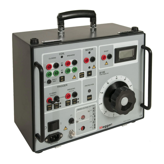
Page 10: Control Panel
Changeover switches (A) and (B) for incoming in coils or spring-charging motors (max 5 A power 115/230/135/250 V AC continuous) Voltmeter ➊ ❻ ❽ ➒ ❷ ❸ ❹ ❺ ❼ ❿ ⓮ ⓫ ⓬ ⓫ ⓬ ⓭ ⓯ ⓱ ⓳ ⓰ ⓲ B10E ZP-BG02E BG0140ME... - Page 11 3 CONTROl PANEl BG0140ME ZP-BG02E B10E...
-
Page 12: Operating Instructions
When the master ON/OFF switch on B10E is turned variable transformer. on, you are ready to proceed with testing. As a rule, output is set for the coil outputs before B10E is Operate the CB. started. Moreover, the coil outputs are usually set for... -
Page 13: Troubleshooting
Make certain that the mains are de-ener- Fault Cause gized on both sides of the CB, and then B10E does not start Master ON/OFF switch is at OFF ground the CB on both sides. position Ground B10E. No output voltage... -
Page 14: Specifications
5 SPECIFICATIONS Specifications SPECIFICATIONS B10E Outputs (DC), CATII COIL, CLOSING/BREAKING Specifications are valid at nominal input voltage and an ambient temperature of +25°C, (77°F). Specifications are subject to change Output voltage 24-300 V DC without notice. Load interval Max 1 s (at currents over 50 mA) - Page 16 ▪ Insulation Power Factor (C&DF) Test Equipment worldwide. ▪ Insulation Resistance Test Equipment Megger is certified according to ISO 9001 and 14001. Line Testing Equipment ▪ Megger is a registered trademark. Low Resistance Ohmmeters ▪...
Need help?
Do you have a question about the B10E and is the answer not in the manual?
Questions and answers