Advertisement
Quick Links
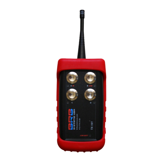
TX-101 and RX-101 Wireless Button Release System
IMPORTANT:
Read and understand this manual before assembling, installing or
using this system. Improper use of this system can cause serious injury.
Table Of Contents
(1) Safety Information....................................................2
(2) Installation.................................................................4
(3) Set Up..........................................................................6
(3.1) RX-101 Receiver..........................................6
(3.2) TX-101 Transmitter....................................8
(4) Operation...............................................................14
(5) Maintenance.............................................................17
(6) Warranty...................................................................18
BRB Systems USA Co.
Instruction Manual
Page
1
Advertisement

Related Manuals for BRB Systems USA TX-101


Summary of Contents for BRB Systems USA TX-101
-
Page 1: Table Of Contents
BRB Systems USA Co. Instruction Manual TX-101 and RX-101 Wireless Button Release System IMPORTANT: Read and understand this manual before assembling, installing or using this system. Improper use of this system can cause serious injury. Table Of Contents Page (1) Safety Information…………………………………………….2 (2) Installation…………………………………..……..…………….4... -
Page 2: Safety Information
Instruction Manual. It is your guide to safe and proper operation of this system. TX-101 Transmitters are 6V powered by 4 AA batteries. AA batteries are small but powerful and must be treated with respect. Never short the ends of the battery together. Never burn the battery, even when you think it is fully discharged. - Page 3 Disconnect this apparatus from its power source during lightning storms or when unused for extended periods of time. Use only the attachment parts/accessories supplied by BRB Systems USA Do not allow liquid entry into the system components.
-
Page 4: Installation
(2) Installation RX-101 Receiver To use the cabling as supplied, each RX-101 Receiver should be mounted vertically and within 10ft of the power and release connections of the trap. To lengthen the power/release cabling use a connector that is rated for outdoor use and meets current electrical standards. - Page 5 2 Trap Receiver Connections Power From Trap 10ft long 4 core cable = Receiver power and trap release connections. Red 12V +ve. Black = 12V –ve. White and Green = trap release connections Trap A. Orientation of the white and green wires is not important. 2 pin socket and plug = trap release connections Trap B.
-
Page 6: Set Up
(3) Set up (3.1) RX-101 Receiver Set Up The receiver identity and operation are set via the three 8 position dipswitches. Receiver Dipswitch Settings Switch numbers are printed on the body of the dipswitch. CODE The (7) CHN switches must match between, TX and RX and ALSO set the frequency CODE CODE CODE... - Page 7 128 possible frequency variations. Using these settings for identification eliminates cross calls between adjacent fields because each field can have a different working frequency. The CHN dipswitch settings on both the RX-101 Receiver and TX-101 Transmitter must match for the system to operate. CODE Signal Encoding Dipswitches The 5 CODE dipswitches (switch 1 on dipswitch SW3 and switches 1,2,3 and 4 on the dipswitch SW2) are the secondary method of receiver identification.
-
Page 8: (3.2) Tx-101 Transmitter
(3.2) TX-101 Transmitter Set Up The Transmitter identity and operation are set via the three 8 position dipswitches accessed by removing the battery cover and the batteries. Transmitter Dipswitch Settings Switch numbers are printed on the body of the dipswitch. - Page 9 Select A Discipline BOTTOM Dipswitch Each TX-101 Transmitter can control 1-4 traps and has different user programmable settings for each discipline and each number of traps. Select how you intend to use the product from the list below.
- Page 10 Button Layouts & Operating Sequences. Single Trap Mode Single Press any button Skeet Mode Single Press A or B Doubles Press either of the A+B Buttons Sporting Mode - 2 Traps Single Press A or B. True Pair Report Pair Press A+B.
- Page 11 Super Sporting 1 – 3 Traps Single Press A, B or C. True Pair PAIR Press PAIR. Press 2 traps of pair together. Report Pair Using Internal Microphone Press PAIR button. Press and release 1 trap. Press and release 2 trap.
- Page 12 Quad Sporting 1 – 4 Traps Single Press and release A, B, C or D. True Pair Press & hold 1 trap of pair. Press & hold 2 trap of pair. Release 1 button. Release 2 button. Report Pair Using Internal Microphone Press &...
- Page 13 Set the shooting disciplines by using switches 1-8 of the BOTTOM dipswitch. See the ‘Transmitter Dipswitch Settings’ diagram. SECOND DELAY To add a 1/6 second delay before the release of the first clay use switch 6 of the BOTTOM dipswitch. This delay is not added to Instant, American or International Skeet modes.
-
Page 14: Operation
TX-101 Transmitter Operation The TX-101 has no power on switch. When you want to use it simply press the appropriate button or sequence of buttons. The unit awakens immediately. - Page 15 Once the button sequence has been correctly entered the TX-101 transmits the information to the RX-101 Receiver. The time between the button being pressed and the Receiver relay closing is less than 1/20 second. Automatic Report Pair In any of the Sporting modes an automatic Report Pair can be released via the units internal report microphone.
- Page 16 The button layout on the TX-101 now becomes: When the SEQ button is pressed the Skeet Sequence Voice Mode is selected. To release a HI target followed by a LOW target, press the SEQ button followed by the HI button. The unit knows that the 2 target is a LOW and so it does not need to be pressed.
-
Page 17: Maintenance
(5) Maintenance The rugged manufacture of the BRB TX-101 and RX-101 should ensure many years of trouble free use if it is not abused and given simple maintenance. Do not allow any component to be immersed in water. Regularly inspect the power/trap control cords for damage. If any wear or damage is found, replace immediately. -
Page 18: Warranty
BRB systems USA Co. does not warrant uninterrupted or error-free operation of the product. BRB Systems USA Co. shall not be liable for loss of revenue or profits, failure to realize savings or other benefits, or any other special, incidental or consequential damages caused by the use, misuse or inability to use this product, regardless of the legal theory on which the claim is based, even if BRB Systems USA Co.
Need help?
Do you have a question about the TX-101 and is the answer not in the manual?
Questions and answers