
Subscribe to Our Youtube Channel
Summary of Contents for Fronius Calibration system 2.0
- Page 1 Operating instructions Calibration system 2.0 Operating instructions 42,0426,0270,EN 012-14032022...
-
Page 3: Table Of Contents
Contents Safety rules Explanation of safety notices General Proper use Environmental conditions Obligations of the operator Obligations of personnel Mains connection Protecting yourself and others Risks from mains current and welding current EMC Device Classifications EMC measures EMF measures Specific hazards Danger from shielding gas cylinders Safety measures at the installation location and during transport Safety measures in normal operation... - Page 4 Connecting the computer to the calibration system and signature pad Preparing the gas calibration system Calibrating the welding system Calibrating other Fronius welding systems Overview - other Fronius devices Connecting the power source and calibration system Connecting the welding wire calibration system...
-
Page 5: Safety Rules
Safety rules Explanation of DANGER! safety notices Indicates immediate danger. ▶ If not avoided, death or serious injury will result. WARNING! Indicates a potentially hazardous situation. ▶ If not avoided, death or serious injury may result. CAUTION! Indicates a situation where damage or injury could occur. ▶... -
Page 6: Proper Use
Proper use The device is to be used exclusively for its intended purpose. Any use above and beyond this purpose is deemed improper. The manufacturer shall not be held liable for any damage arising from such usage. Proper use includes: carefully reading and following all the instructions given in the operating in- structions studying and obeying all safety and danger notices carefully... -
Page 7: Mains Connection
Mains connec- Devices with a higher rating may affect the energy quality of the mains due to tion their current consumption. This may affect a number device types in terms of: Connection restrictions Criteria with regard to the maximum permissible mains impedance Criteria with regard to the minimum short-circuit power requirement at the interface with the public grid see "Technical data"... -
Page 8: Emc Device Classifications
The device must only be operated on a mains supply with a ground conductor and a socket with a ground conductor contact. If the device is operated on a grid without a ground conductor and in a socket without a ground conductor contact, this will be deemed gross negligence. The manufacturer shall not be held liable for any damage arising from such usage. -
Page 9: Emf Measures
Earthing of the workpiece If necessary, establish an earth connection using suitable capacitors. Shield, if necessary Shield other devices nearby Shield the entire welding installation EMF measures Electromagnetic fields may pose as yet unknown risks to health: Effects on the health of persons in the vicinity, e.g. those with pacemakers and hearing aids Individuals with pacemakers must seek advice from their doctor before ap- proaching the device or any welding that is in progress... -
Page 10: Danger From Shielding Gas Cylinders
corrosion or changes caused by other environmental factors). The testing interval and scope of testing must comply with applicable national standards and directives as a minimum. Danger from Shielding gas cylinders contain gas under pressure and can explode if damaged. shielding gas cyl- As the shielding gas cylinders are part of the welding equipment, they must be inders... -
Page 11: Safety Measures In Normal Operation
Calibration of Regular calibration is required to guarantee the traceability to national or inter- the calibration national standards of calibrations performed with this calibration system. system Fronius recommends a 12-month calibration interval. For more information, please contact your Fronius partner. -
Page 12: Disposal
Disposal Do not dispose of this device with normal domestic waste! To comply with the European Directive on Waste Electrical and Electronic Equipment and its imple- mentation as national law, electrical equipment that has reached the end of its life must be collected separately and returned to an approved recycling facility. Any device that you no longer require must either be returned to your dealer or given to one of the approved collection and recycling facilities in your area. -
Page 13: General Information
General information... -
Page 15: General
General Device concept The 2.0 calibration system is designed for calibrating power sources. All types of Fronius power sources can be calibrated under static load using this system. Both DC and AC devices can be calib- rated. The calibration system is suitable for quick and easy calibration of the power source in situ. -
Page 16: Crane Transport
Do not walk under the device when it is being suspended in an elevated posi- tion or dwell in hazardous locations ▶ Exclusively use load-carrying equipment approved by Fronius ▶ Attach 4 chains or 4 ropes to the 4 suspension points ▶... -
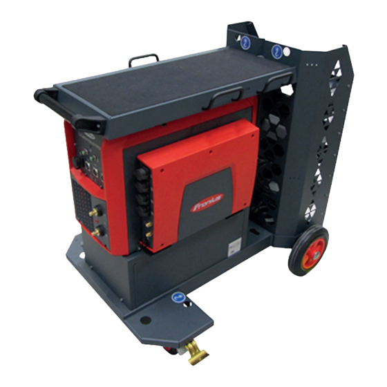
Page 17: Accessories And Options
Accessories and options Interface and trolley Interface calibration system Trolley calibration system 4,050,211 4,077,022 Accessories (1) (2) (3) (5) (6) (17) (16) (15) (14) (13) (12) (11) (10) - Page 18 Item no. 1 x mains cable, 5 m 43,0004,2862 1 x Euro/central connector adapter with Tuchel socket 44,0350,5407 1 x Fronius/central connector adapter 44,0350,4504 1 x (+) power cable with sense lead (red) 43,0004,5883 1 x LocalNet passive splitter 4,100,261...
-
Page 19: Options
Further accessories (not pictured) Description Item no. 1 x power adapter 4051091 1 x connection cable for gas sensor, 5 43,0004,5914 1 x 1.6 m SpeedNet cable 4051021 2 x 5 m SpeedNet cable 4051022 2 x insulating sleeve adapter 42,0100,1411 1 x 2.5 m 8-pin data cable, PUR 43,0004,4361... -
Page 20: Required For Calibration
Collaboration Perfect Welding / Products & Services PW General Topics / Services Securing Services Categories / Calibration 04_cal_software_releases Hardware & ac- Calibration system 2.0 cessories Interface calibration system Welding wire calibration system Accessories calibration system Trolley calibration system Required for cal-... - Page 21 For the calibration of WeldCube Connector U/I/WFS Euro and WeldCube Con- nector Advanced + Euro: PoE injector, RJ45 30 W / 802.3at / PoE+ (42,0411,0213) M12-X / RJ45 network cable, 5 m (42.0411.0232) TPS 500i power source WF 25i / WF 30i wirefeeder with Euro central connection alternatively WF 25i / WF 30i wirefeeder with adapter ZA FSC-S-G/Euro STD (44,0350,3565)
-
Page 23: Controls, Connections And Mechanical Components
Controls, connections and mechan- ical components... -
Page 25: Controls And Connections On Calibration System
(12) (13) (14) (15) (16) (17) (18) Calibration system 2.0 with interface calibration system Item Description (+) power connection (red) (+) sense lead connection socket (red) (-) sense lead connection socket (blue) (-) power connection (blue) USB port computer/laptop USB port for adapter... -
Page 26: Rear Of Device (Without Trolley)
(16) Gas IN connection socket (option) (17) Gas OUT connection socket (option) (18) Data connection socket (option of connecting to the calibration system) Rear of device Item Designation (without trolley) F5 fuse (2 A slow-blow) 24 V PLC fuse protection F4 fuse (2 A slow-blow) 24 V PLC fuse protection Mains cable connection... -
Page 27: Mechanical Components On Trolley
Mechanical components on trolley Calibration sys- Item Designation tem trolley Calibration system trolley (option) Accessory drawers Cable hanger Tray Storage trays... -
Page 29: Installation
Installation... -
Page 31: Installing The Calibration System
NOTE! If a version of TwinCat is already present on your PC (TwinCat 2 or TwinCat 3), installation is not mandatory. However, Fronius recommends that the version of TwinCat provided is used. Open the path: \WT_SW_Fronius_CalibrationSystem2.0_vX.X.XX.X_MULTI\twincat Install the file located there and follow the setup instructions... -
Page 32: Tps/I Smartcard Driver
Depending on the operating system, select the subfolder (win / win_64) and follow the instructions After successful installation, the driver can be found under the network ad- apters: Network adapters Microsoft Virtual WiFi Miniport Adapter If a driver is already installed, ensure that it is the latest version and if necessary update it Also use the connected USB port for future work with the calibration system. -
Page 33: Localnet Ftdi Driver
LocalNet FTDI Connect the power source with LocalNet to the calibration system via USB driver and switch on both components Open the Device Manager If no driver is yet installed, the device will appear as unknown (USB Serial Port, USB-RS232 cable, etc.) Unknown Unknown Install the required driver software from the unzipped software package:... -
Page 34: Changing Network Settings
Changing net- Setting network settings work settings via the calibration software: b) under the network settings (TCP/IPv4) of the adapter: Internet protocol, version 4 (TCP/IPv4) Properties Changing the IMPORTANT! Prerequisites for USB calibration: network settings DHCP server, which starts automatically when the program starts. for USB calibra- .net Framework, at least version 4.7.2 tion... -
Page 35: Setting A Twincat Route
Action if the IP address 192.168.125.1 is not displayed on the power source: Check if the DHCP server is running (icon!) If the DHCP server is not running, restart the software. Disconnect the USB briefly from the power source and reconnect it again Only connect the USB Ethernet adapter to the calibration system, not to the computer/laptop Setting a Twin-... - Page 36 Deactivate "Encrypt password (Twincat 3 only)" If connection is successful, an X is displayed in the overview. Close the window by clicking "Close" Possible errors/points to check if the route cannot be set as described above in- clude: Check network settings: The calibration station must be accessible in the Windows command prompt (CMD) at the IP address 192.168.120.50 with the ping command.
-
Page 37: Setting The Language, System Information
Setting the language, system information Setting the lan- guage After the calibration software has been installed, the language can be set for the user interface: The system switches to the chosen language when the program is restarted. NOTE! Only the user interface of the calibration software is displayed in the chosen language. -
Page 39: Calibrating Welding Systems
Calibrating welding systems... -
Page 41: General Information
General information Mains voltage With single-phase machines, the mains voltage must be measured manually us- measurement ing a FLUKE measuring device. for single-phase power sources Enter the measured mains voltage in the box [ ] Enable In Use Under external measuring equipment, enter the FLUKE measuring device used Correcting set If the values specified by the calibration software are not achieved, the set value... -
Page 42: Calibrating Welding Systems With Localnet (Tps, Tst, Mw, Tt)
Calibrating welding systems with LocalNet (TPS, TSt, MW, TT) Overview - Loc- Welding systems with external wirefeeder alNet TS 4000 / 5000 TPS 3200 / 4000 / 5000 TIME 5000 Digital CMT 4000 Advanced TSt 3500/5000 TSt 3500 / 5000 Rob TSt 3500 / 5000 Syn TSt 4000 / 5000 Pulse Welding systems with integrated wire drive... - Page 43 Connect the (+) power cable to the calibration system and the power source Connect the sense lead (red) to the calibration system Connect the (-) power cable to the calibration system and the power source Connect the sense lead (blue) to the calibration system Connect the LocalNet/USB con- verter to the calibration system...
- Page 44 WARNING! An electric shock can be fatal. All work on the power source may only be carried out in a de-energised state. Before opening the device ▶ Move the mains switch to the "O" position ▶ Unplug the device from the mains ▶...
-
Page 45: Connecting The Welding Wire Calibration System
Connecting the NOTE! welding wire cal- ibration system The power cables are not relevant for calibration of the welding wire! Establish data communication between the following: ▶ power source and calibration system (LocalNet, SpeedNet, USB, etc.) ▶ power source and wirefeeder (LocalNet, SpeedNet, USB, etc.) ▶... -
Page 46: Connecting The Computer To The Calibration System And Signature Pad
Secure the welding torch in the welding wire calibration system at the contact tip Make sure that the torch hosepack is arranged as straight as possible NOTE! When calibrating robot welding systems, the welding wire calibration system is usually attached to the contact tip of the robot welding torch. If, in this case, it is not possible to attach it properly, the following longer contact tips may be used on the robot welding torch: 42,0001,0056... - Page 47 Connect the Signotec signature pad to the calibration system...
-
Page 48: Preparing The Gas Calibration System
Preparing the IMPORTANT! If a shielding gas supply is to be calibrated, it must be connected gas calibration to the calibration system before starting the calibration process. system The welding system and calibration system must be connected to each other. Connect the gas hose to the pres- sure regulator and to the Gas IN connection on the calibration sys-... -
Page 49: Calibrating The Welding System
Calibrating the IMPORTANT! Before starting the calibration process: welding system All devices to be calibrated must be connected to the calibration system: power source, wirefeeder, shielding gas supply; etc. The power source to be calibrated must be switched on at least 5 minutes before the calibration process starts. - Page 50 Under Settings, select the connection to the power source: o LocalNet Click on [Establish connection] If the connection is established successfully, a message to this effect is dis- played and the data from the power source and wirefeeder is automatically read in.
- Page 51 Click [Start automatic calibration] The calibration process starts. When a calibration process is active: A corresponding notification is displayed The [Interrupt calibration] button is available All measuring points are checked one after the other Current measured values are displayed A progress bar with the remaining time is displayed If the calibration process is interrupted before the welding wire has been cal- ibrated, a corresponding notification is displayed.
- Page 52 Press [OK] on the Signotec signature pad The signature is sent to the calibration software. x ... Cancel signature Refresh ... new signature A corresponding notification is displayed after the signature has been re- ceived successfully. Click [Create PDF] IMPORTANT! Only after the confirmation "PDF created successfully!" is dis- played, will the calibration report be saved.
-
Page 53: Calibrating Welding Systems With Speednet (Tps /I, Iwave 300I - 500I)
Calibrating welding systems with SpeedNet (TPS /i, iWave 300i - 500i) Overview - MIG/MAG welding systems with external wirefeeder SpeedNet TPS 320i / 400i / 500i / 600i TPS 400i LSC ADV MIG/MAG welding systems with integrated wire drive TPS 270i C TPS 320i C TIG welding systems iWave 300i - 500 DC... -
Page 54: Connecting The Computer To The Calibration System And Signature Pad
Connect the welding torch to the welding system Remove the gas nozzle from the welding torch Thread the wire The welding wire should protrude approx. 200 mm from the contact tip. Thread the welding wire into the intake part of the sensor Use clamps to secure the welding torch in the welding wire calibration system at the contact tip Make sure that the torch hosepack is arranged as straight as possible... -
Page 55: Calibrating The Welding System
Connect the gas and data connec- tions to each other Calibrating the IMPORTANT! Before starting the calibration process: welding system All devices to be calibrated must be connected to the calibration system: power source, wirefeeder, shielding gas supply; etc. The power source to be calibrated must be switched on at least 5 minutes before the calibration process starts. - Page 56 Enter the details for a new client: Name Address Postcode Customer number Click on [Add] select current client from the list shown Under Others, inventory numbers, order numbers and observations can be entered. Click [Next >] The preliminary settings / device selection are displayed. Under Settings, select the connection to the power source: o SpeedNet Click on [Establish connection]...
- Page 57 Click [Next >] The preliminary settings / general measurement data are displayed: Ambient temperature [° C] Mains voltage [V] Open circuit voltage U If no data is displayed, it can be found by clicking on [Start measuring pro- cess]. If there is still no data displayed, check the F2 and F3 fuses on the back of the calibration system.
- Page 58 CAUTION! Risk of injury from emerging welding wire. As soon as the calibration process resumes, the welding wirefeed starts and the welding wire emerges. ▶ Keep the welding wire calibration system away from the head and body and wear suitable protective goggles. ▶...
-
Page 59: Calibrating Welding Systems With Usb / Speednet
Calibrating welding systems with USB / SpeedNet Overview - USB Software version 1.0.28 and higher: TIG welding systems iWave 230i DC iWave 190i / 230i AC/DC MIG/MAG welding systems with external wirefeeder TPS 320i / 400i / 500i / 600i TPS 400i LSC ADV MIG/MAG welding systems with integrated wire drive TPS 270i C... -
Page 60: Connecting The Welding Wire Calibration System
Connecting the NOTE! welding wire cal- The power cables are not relevant for calibration of the welding wire! ibration system Establish data communication between the following: ▶ power source and calibration system (LocalNet, SpeedNet, USB, etc.) ▶ power source and wirefeeder (LocalNet, SpeedNet, USB, etc.) ▶... -
Page 61: Calibrating The Welding System
Connect the gas hose to the wirefeeder or the power source and to the Gas OUT connection on the calibration system Connect the gas and data connec- tions to each other Calibrating the IMPORTANT! Before starting the calibration process: welding system All devices to be calibrated must be connected to the calibration system: power source, wirefeeder, shielding gas supply;... - Page 62 Click on [Add] select current contractor from the list shown Enter the serial numbers of the measuring equipment: Calibration system Welding wire calibration system Gas measurement system Click [Next >] The preliminary settings / customer data are displayed. Enter the details for a new client: Name Address Postcode...
- Page 63 Click [Next >] The preliminary settings / calibration parameters are displayed: five measured values M1 - M5 for each power source Welding current [A] Welding voltage [V] For the wirefeeder, enter five wire speed measured values M1 - M5 [m/min]: The measured value M5 is the maximum value for the wirefeeder.
- Page 64 Change over the welding system for calibration of the welding wire: (see page onwards) Connect welding wire calibration system and calibration system (+) Disconnect power cable from welding system Connect the welding torch to the welding system Remove the gas nozzle from the welding torch Thread the wire Thread the welding wire into the sensor Secure the welding torch in the welding wire calibration system...
-
Page 65: Calibrating Other Fronius Welding Systems
TransPocket 1100 / 1200 / 1400 / 1500 / 2000 TransPocket 2500 / 3500 - RC, TIG, Comfort AccuPocket 150 The Fronius power sources listed above do not have a SpeedNet or LocalNet port and are calibrated using the following calibration process. Connecting the... -
Page 66: Connecting The Welding Wire Calibration System
Connecting the NOTE! welding wire cal- The power cables are not relevant for calibration of the welding wire! ibration system Establish data communication between the following: ▶ power source and calibration system ▶ power source and wirefeeder ▶ welding wire calibration system and calibration system Connect the connection cable to the welding wire calibration system IMPORTANT! A maximum of 3 connection cables (max. -
Page 67: Calibrating The Transpocket Welding System
Calibrating the IMPORTANT! Before starting the calibration process: TransPocket The power source to be calibrated must be connected to the calibration sys- welding system tem. The power source to be calibrated must be switched on at least 5 minutes before the calibration process starts. The calibration process is started from the calibration software on the com- puter / laptop. - Page 68 Click [Next >] The preliminary settings / device selection are displayed. Under Settings, select: o Fronius devices Select the respective TransPocket variant Enter the serial number and name of the power source Click [Next >] The preliminary settings / calibration parameters are displayed:...
- Page 69 Click [ Start measuring process ] Enter the value displayed on the power source in the Display [A] box Click [Next >] Repeat steps 24 - 27 for the measured values M2 - M5 - M1 (10 measurements) When the calibration process is complete, a corresponding notification is dis- played and the [Print calibration report] button is available.
-
Page 70: Calibrating Transtig 1750 Puls
Calibrating Tran- IMPORTANT! Before starting the calibration process: sTig 1750 Puls All devices to be calibrated must be connected to the calibration system: power source, shielding gas supply, etc. The power source to be calibrated must be switched on at least 5 minutes before the calibration process starts. - Page 71 Click [Next >] The preliminary settings / device selection are displayed. Under Settings, select: o Fronius devices Select TransTig 1750 Puls Click [External start with calibration system] Enter the serial number of the TT 1750 Puls in the box Click [Next >]...
- Page 72 Carry out a visual inspection of the welding system and the calibration sys- tem, according to the calibration instructions If the visual inspection does not reveal any defects, select [Click here] Click [Next >] The summary of the calibration process is displayed. Define the calibration class: o Precision o Standard...
- Page 73 Click [Create PDF] IMPORTANT! Only after the confirmation "PDF created successfully!" is dis- played, will the calibration report be saved.
-
Page 74: Calibrating Variosynergic 3400
Calibrating Vari- IMPORTANT! Before starting the calibration process: oSynergic 3400 The power source to be calibrated must be connected to the calibration sys- tem (if possible, connect the relevant adapters). The power source to be calibrated must be switched on at least 5 minutes before the calibration process starts. - Page 75 Click [Next >] The preliminary settings / device selection are displayed. Under Settings, select: o Fronius devices Select VarioSynergic 3400 [Display available] and [External start with calibration system] have been pre- selected Enter the serial number of the VarioSynergic in the box Welding current, welding voltage and wire speed have been pre-selected.
- Page 76 Set the toggle switch to A (current) Set the selector switch on the interior of the device to 2-step mode. Click [Start measuring process] Carry out a visual inspection of the welding system and the calibration sys- tem, according to the calibration instructions If the visual inspection does not reveal any defects, select [Click here] Click [Next >] The summary of the calibration process is displayed.
- Page 77 Repeat steps 24 - 29 for the welding voltage At the end of the current and voltage calibration, the message [Start calibra- tion feed system 1!] is displayed To calibrate the welding wire on the power source, specify the following set- tings: Set the toggle switch to wirefeeder.
- Page 78 After about 3 seconds of wirefeeder running time, click on "Start measuring process" in the calibration program and release the torch trigger Enter the value displayed on the power source under "Display" and click on [Next >] Repeat steps 43 - 45 for the measurement of M2 to M5 and M1 When the calibration process is complete, a notification is displayed to this effect and the [Print calibration report] button is available.
- Page 79 Notes on voltage calibration: The maximum voltage during calibration is 30 V. The same resistance of 480 mOhm is used for all measuring points. The calibration software automatically specifies the measuring points to be measured. The voltage is regulated by the current; the predefined current values are standard values and may have to be adjus- ted to achieve the specified voltages.
- Page 80 Click [Next >] The preliminary settings / device selection are displayed. Under Settings, select: o Fronius devices Select TransTig 170 / 210 Click [External start with calibration system] Enter the serial number of the TT 170 / 210 in the box Click [Next >]...
- Page 81 Click [Next >] The summary of the calibration process is displayed. Define the calibration class: o Precision o Standard Set the specified measured value M1 on the power source Click [ Start measuring process ] Enter the value displayed on the power source in the Display [A] box Click [Next >] Repeat steps 25 - 28 for the measured values M2 - M5 (5 measurements)
-
Page 82: Calibrating Weldcube Connector
Calibrating WeldCube Connector Overview WeldCube Connector with current/voltage measurement: WeldCube Connector U/I WeldCube Connector Advanced A TPS 500i power source is used when calibrating the WeldCube Connector. System layout as shown in the figure on page with the following exceptions: no wirefeeder no WCC Euro wire sensor no Euro/central connector adapter with Tuchel socket... - Page 83 CALSYS WF 15i / 25i / 30i Euro TPS 500i CALSYS = calibration system 2.0, WCC = WeldCube Connector, PoE = Power over Ethernet * = Euro/central connector adapter with Tuchel socket NOTE! If there is a power connector for the high current socket on the power source, use the adapter for the high current sockets to bayonet (42,0001,4482).
-
Page 84: Connecting The Welding Wire Calibration System
Connecting the NOTE! welding wire cal- In conjunction with the WeldCube Connector, wire calibration takes place in the ibration system course of the system calibration. Following the first current-voltage calibration, a prompt to start wire calibration appears in the calibration software. Before confirming the prompt: ▶... -
Page 85: Calibrating Weldcube Connector
Connect the gas hose to the pres- sure regulator and to the Gas IN connection on the calibration sys- max. supply pressure: 5 bar Connect the gas hose to the wirefeeder or the power source and to the Gas OUT connection on the calibration system Connect the gas and data connec- tions to each other... - Page 86 Start the calibration program Click [New calibration] The preliminary settings / contractor data are displayed. Enter the details for a new contractor (= Person performing calibration): Name Address Postcode Calibration technician Click on [Add] select current contractor from the list shown Enter the serial numbers of the measuring equipment: Calibration system Welding wire calibration system...
- Page 87 Select WeldCube Connector Setup Take smartphone to the WeldCube Connector Follow the instructions in the installation wizard (Setup 1 - 6) Following the 6 setup steps, the WeldCube Connector will be ready to con- nect to the calibration software. Click on [Establish connection] in the calibration software If the connection is established successfully, a message to this effect is dis- played and the data from the power source and wirefeeder is automatically read in.
- Page 88 Define the calibration class: o Precision o Standard Click [Start automatic calibration process] The calibration process starts. When a calibration process is active A corresponding notification is displayed The [Interrupt calibration] button is available All measuring points are checked one after the other Current measured values are displayed A progress bar with the remaining time is displayed If the calibration process is interrupted before the welding wire has been cal-...
- Page 89 WF 15i / 25i / 30i Euro CALSYS TPS 500i CALSYS = calibration system 2.0, WCC = WeldCube Connector, PoE = Power over Ethernet * = Euro/central connector adapter with Tuchel socket Confirm the prompt to change the polarity of the WeldCube Connector with The calibration process resumes.
-
Page 91: Troubleshooting
Troubleshooting... -
Page 93: Troubleshooting
Troubleshooting The status indic- No power supply ator is not lit up Cause: Mains cable not connected Remedy: Connect the mains cable Cause: Faulty mains cable Remedy: Check the mains cable and replace if necessary Cause: Fuses F1 / F4 / F5 have tripped Remedy: Switch off the device, disconnect it from the mains, and check fuses, e.g.:... -
Page 94: No Usb/Speednet Connection
No USB/Speed- No USB/SpeedNet connection between power source and calibration software Net connection Cause: USB connection error Remedy: Check that the USB Ethernet adapters are properly plugged into the power source and calibration system. Check the Ethernet connection cable for any possible damage and for functionality. -
Page 95: Technical Data
Technical data... -
Page 97: Technical Data
Technical data Calibration sys- Mains voltage 100 - 240 V AC tem 2.0 Mains voltage tolerance +15 / -10 % Mains frequency 50/60 Hz Mains fuse protection (slow-blow) Primary current 3 A @ 100 V AC 1.5 A @ 240 V AC cos phi power factor 0.99 Internal power supply... -
Page 98: Interface Box
Interface box Operating voltage 24 V DC Degree of protection IP 20 EMC device class EN 61010 -1:2010 Safety symbols Dimensions l x w x h 466 x 355 x 85 mm Weight (incl. gas measurement I-kit) 3.85 kg Ambient temperature 0 –... - Page 100 SPAREPARTS ONLINE Fronius International GmbH Froniusstraße 1 4643 Pettenbach Austria contact@fronius.com www.fronius.com Under www.fronius.com/contact you will find the adresses of all Fronius Sales & Service Partners and locations.
Need help?
Do you have a question about the Calibration system 2.0 and is the answer not in the manual?
Questions and answers